Download as PDF, PPTX


![Devaprakasam D, Email: devaprakasam.d@vit.ac.in, Ph: +91 9786553933
Solution
The forces at A are,
TAB, TAC, TAD and P
P= P j. Express all the forces in unit vectors I, j, k
AB= - 4.2 i- 5.6j ; |AB|= 7.00 m
AC = 2.4 i+ -5.6j+ 4.2k; |AC|=7.4m
AD=-5.6 j - 3.3 k; |AD|= 6.5m
TAB = TAB λAB = [-0.6i-0.8j] TAB
TAC = TAC λAC =[0.3240i-756j+0.567k] TAC
TAD = TAD λAD = [-0.861j-0.5076k] TAD
Equilibrium condition
0F TAB + TAC + TAD +Pj =0
Substituting the values of TAB ,TAC , TAD
Equating the I, j, k components to zero
We will get TAB =259 (known) , TAC =479.15N , TAB =535.66 N, P=1031N](https://image.slidesharecdn.com/me202engineeringmechanicsl3-150714064349-lva1-app6892/85/Me202-engineering-mechanics-l3-16-320.jpg)


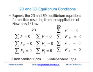
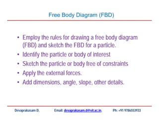
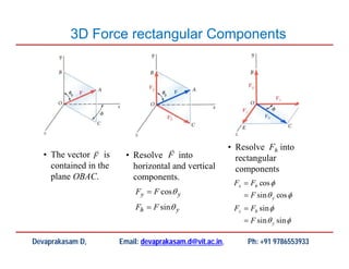
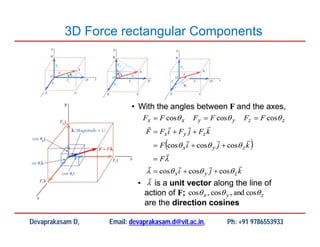
This document contains lecture material from Dr. Devaprakasam Deivasagayam for the course ME202: Engineering Mechanics. It discusses key concepts related to 2D and 3D equilibrium conditions including: - Expressing the 2D and 3D equilibrium equations for particles based on Newton's first law of motion. - The process for drawing accurate free body diagrams by identifying forces, establishing a coordinate system, isolating the body, and representing external forces. - Calculating the rectangular components of forces acting at angles in 3D space. - Examples of solving equilibrium problems by applying the 3D force component equations. - Homework being assigned on the topic of moment, which


