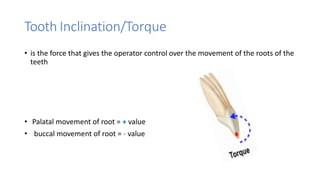
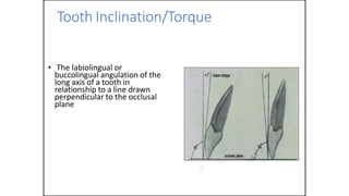
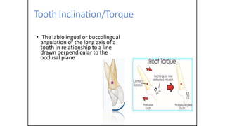
8. Tooth Inclination/Torque
• is the force that gives the operator control over the movement of the roots of the
teeth
• Palatal movement of root = + value
• buccal movement of root = - value
9. Tooth Inclination/Torque
• The labiolingual or
buccolingual angulation of the
long axis of a tooth in
relationship to a line drawn
perpendicular to the occlusal
plane
90
º
10. Tooth Inclination/Torque
• The labiolingual or buccolingual
angulation of the long axis of a
tooth in relationship to a line
drawn perpendicular to the
occlusal plane
11. Edgewise Appliance
🞅These brackets were attached to bands and were
made of soft gold
🞅Complex wire bending was required to
control tooth position in all three planes
🞅This was time consuming process and needed
considerable skills from the orthodontist
13. First generation (Andrew)/SWA
• The pre-adjusted edgewise brackets have tip, torque, in and out bends built within
the brackets
14. First generation (Andrew)/SWA
• The pre-adjusted edgewise brackets have tip, torque, in and out bends
built within the brackets
15. First generation (Andrew)/SWA
• It was proposed that this appliance does not require wire bending during
treatment hence the name straight wire appliance (SWA) was given to it .
• Andrew developed different brackets for different skeletal patterns and for
extraction and non-extraction cases , results in large no. of brackets
• Is not a wide range system (no Max. Versatility )
16. First generation (Andrew)/SWA
• Roller-coaster effect due to excessive force and use of elastic retraction
mechanics Deeping of anterior bite with creation of lateral open bite .
17. SECOND GENERATION /ROTH
• Roth devised one set of brackets applicable for most cases ( small
inventory) .
• His arch form was wider than Andrews' in order to avoid damage to canine Tips
during treatment and to assist in obtaining good protrusive function.
• Over correction, especially in torque of brackets to accommodate
relapse and diminution of force .
18. MBT
MCLAUGHLIN. BENNETT, AND TREVISI
The MBT is the 3rd generation of
preadjusted bracket system was
introduced by three orthodontist
in 1997.
They introduced their own
prescription of brackets called
MBT prescription.
19. MBT
MBT prescription was based on following principles:
• Light continuous force
To provide faster movement with less root
resorption and less adverse effect, still the
optimal tooth movement of fixed
appliance is the light continuous force.
20. MBT
• Lacebacks and bendbacks
Limits incisor proclination during
alignment by controlling mesial tip of
canines and provide better anchorage
control
21. MBT
• Sliding mechanics on a 0.019”x0.025”
SS wire in 0.022”x0.028” slot bracket
insure wider range of torque degree with
less friction and good anchorage.
22. MBT
• Use of specific arch form close to
patient natural arch form
three different arch forms
were advocated, these were tapered,
ovoid and square arch form for better
finishing and less extractions
tapered square
ovoid
23. MBT
• Bracket selection
in specific malocclusions and alteration of
prescription in some specific clinical
problem.
and can be used to save
chairside time in the finishing stages of
treatment.
24. MBT
• Bracket positioning
at specific height on the teeth taking
guidance from bracket
positioning charts and using specific
bracket positioning gauges .
25. MBT
• Using curves in the wire to level curve
of spee
The MBT bracket system adujst the
occlusal level and curve of spee
33. MBT
The main differences with other bracket prescriptions are:
Increased palatal root torque in the upper central incisor brackets
(Andrews: 7 degrees , Roth: 12 degrees, MBT: 17 degrees)
34. Increased palatal root torque in the upper lateral incisor brackets
(Andrews: 3 degrees, Roth: 8 degrees, MBT: 10 degrees)
37. indication of MBT appliance
• Class II cases
i. in camaflage of class II div 1 by u4s extraction (enmass retraction)
ii. in class II elastics
• class I cases
i. in non extraction cases (under size wire)
• Mild class III cases
treated by torque of upper and lower (full size wire)
38. indication of MBT appliance
• Class II cases
i. in camaflage of class II div 1 by u4s extraction (enmass retraction)
40. indication of MBT appliance
• Class II cases
ii. in class II elastic
41. indication of MBT appliance
• class I cases
i. in non extraction cases (under size wire)
42. indication of MBT appliance
• Mild class III cases
treated by torque of upper and lower (full size wire)
43. indication of Roth appliance
• In class I cases
i. spacing treated by loss of anchorage
ii.crowding treated by extraction
• In class III
i.retroclined upper incisors
ii.class III elastics
• posterior cross bite
• dosn’t deal well with class II
47. 1. Bracket inverting
Also known as flipping, refers to rotating the bracket 180°.
Flipping reverses the torque but doesn’t alter the tip.
Flipping a bracket 180° or switching it between the right and
left sides of the arch can be useful in altering the prescription
for biomechanical purposes.
48.
49. Case Scenario
Class II Div. I with Palatally Displaced Lateral Incisor
Standard Bracket
MBT
Torque
+ ve 10
Palatal Root Torque
56. 3. Bracket swapping
• Crossing the midline by placing
a bracket on the opposing tooth
in the same arch.
• Swapping bracket between right
and left sides alter the tip but
doesn’t affect torque.
64. In summary
Moving brackets across the occlusal line
reverses tip and torque
Crossing the midline reverses tip
Whereas flipping the bracket reverses
the intended torque expression
68. Axial positioning
It is the angle or inclination of the bracket
relative to the tooth's long axis.
(Andrews proposed using the facial axis of the clinical
crown as a reference for axial positioning of bracket)
Improper bracket axial position will cause an
increase or decrease in the positive or negative tip
69. some clinical scenarios hybrid axial positioning can be used to
compensate for an insuffcien built-in prescription
70. Mesiodistal position
The mesiodistal position refers to the placement of the bracket along
the tooth's width
Andrews proposed that brackets be placed on the mid developmental ridges
of the teeth for proper mesiodistal alignment
71. • The mesiodistal center of maxillary and mandibular
incisors and mandibular premolars is located at the mid-
developmental ridge.
• in cuspids, it is slightly mesial to the mesiodistal center.
• maxillary premolars, brackets are placed 0.5 mm mesial
to join the buccal and palatal cusps.
• recommended in patients with rotated teeth, In case of
rotated teeth the bracket should always be placed more on
side of rotation in the mesiodistal plane
72. Vertical positioning
• The vertical position refers to the height of the bracket on the
tooth
• brackets’ vertical positioning allows more variations than mesiodistal
and axial positioning.
• When changing the vertical position of the bracket, it is important to
consider the principle of the positive-negative torque zone that
results in different torque expressions when the vertical position of
the same bracket is altered
75. • Gingivally positioned brackets on on maxillary incisors, maxillary
canines,mandibular canines, and all posterior teeth produce an
exaggerated buccal or labial root torque expression due to their
curved facial surfaces in the occlusogingival direction
• changing the vertical position of a mandibular incisor bracket
minimally affects torque as these teeth have fat or nearly fat
labial surfaces
• Incisally positioned brackets or occlusally, further away from the
center of rotation, torque is expressed as a crown movement
rather than a root movement and vice versa
78. • A hybrid bracket system combines ligation bracket systems (self-
ligation and conventional ligation) and brackets with different
slot sizes (0.022-in and 0.018-in) and slot widths.
A combination of anterior active self-ligating brackets (ASLB) or
conventional brackets with posterior passive self-ligating
brackets (PSLB) has been claimed to reduce alignment time,
improve incisor torque control and sliding mechanics.
79. The concept of a hybrid or differential bracket slot was introduced by
Schudy anterior 0.016 £ 0.022-in slot brackets and posterior 0.022 £
0.028-in slot brackets.
Another modifcation was proposed by Gianelly employing 0.018-in slot
incisor brackets and 0.022-in slot canine/premolar brackets along with
0.018 £ 0.022-in working archwire.
Gianelly’s bidimensional bracket system was intended to optimize anterior
anchorage during the closure of extraction spaces in minimal anchorage
patients. However, there was reduced torque control of the posterior
teeth.
80. • Because the width of a bracket impacts its base surface area, and as a result, its shear
bond strength, profft et al have advocated that the width of the bracket be about half
the width of the tooth
• The width of a bracket also impacts the mechanical interaction at the slot/wire
interface the wider the bracket, the longer the moment arm, and the smaller the
contact angle WHICH IS provide better rotational and mesiodistal control of root
position and reduced frictional resistance during sliding.
In contrast, increased bracket width reduces the interbracket distance, increasing
archwire stiffness and reducing its range, potentially resulting in slower alignment and
torque expression
81. In conclusion…
there is no differencebetween 0.018-in and 0.022-in slot brackets. However,
combining the two slot sizes may offer better torque control during incisor
retraction.
There is some evidence that combining anterior ASLB and posterior PSLB reduces
the duration of the alignment phase, improves incisor torque control, and
facilitates sliding mechanics.
There is no single bracket prescription that is appropriate for all clinical situations.
Therefore, alteration of the built-in prescription is recommended.
Hybrid vertical positioning infuences torque expression.
83. CAD/CAM in orthodontic
Uses
• documentation
• study casts
• analysis of a dental malocclusion
• smile designing
• treatment planning
• fabrication of orthodontic appliances . Including
brackets
• Customized brackets with patient-specific teeth morphology and torque by analyzing the
slot location
84. 3D digital scan combined with 3D x-ray and clinical photographs
87. • Less number of TTT appointment.
• TTT of complex cases such multiple missing teeth, or
dentofacial deformities.
• generate different three- dimensional (3D) digital
models then choose the best treatment option.
Advantages
• High cost
• Technique sensitive
• discrepancies remain between the virtual
plan and the final outcome
disadvantages