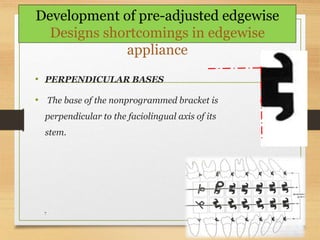
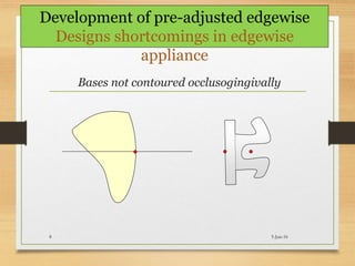
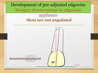
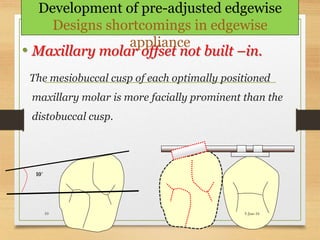
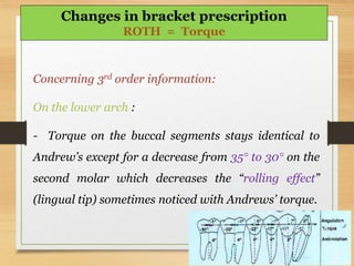
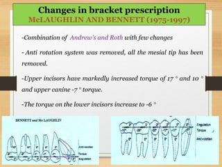
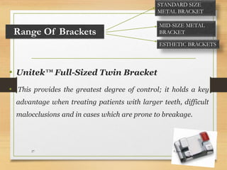
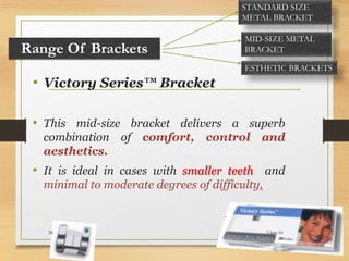
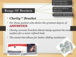
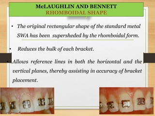
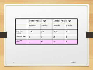
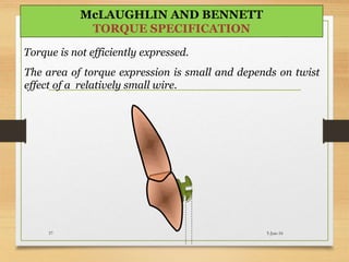
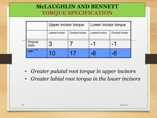
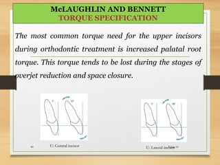
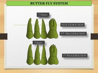
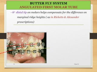
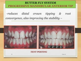
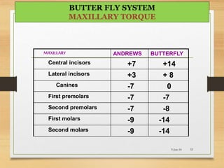
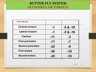
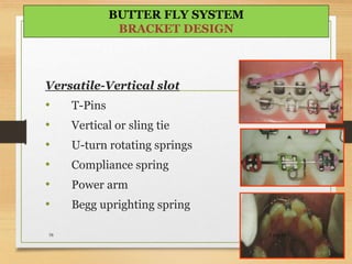
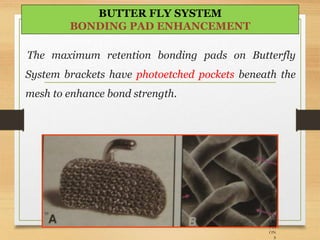
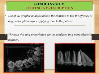
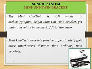
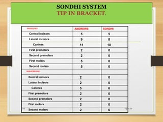
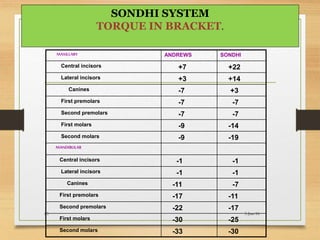
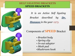
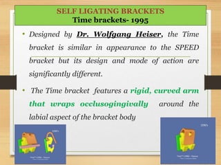
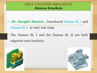
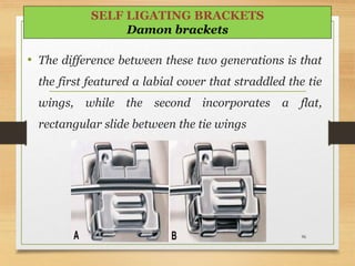
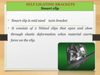
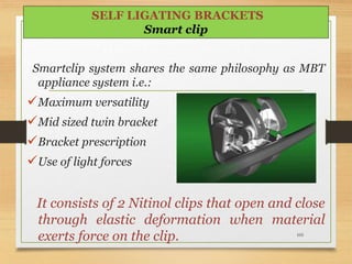
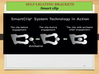
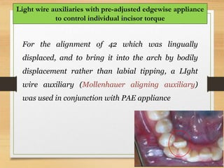
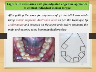
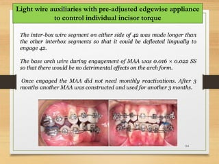
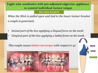
RECENT TRENDS IN
PRE-ADJUSTED EDGEWISE
APPLIANCES (PEA)
Presented by
Dr. Jitendra Raghuwanshi
PG-2nd year
SEMINAR NO -07 DATE 01/06/16
2
 Introduction of PEA
 Shortcoming of Edgewise appliances
 Development of PEA
 Changes or recent bracket
prescriptions
• Andrews prescription
• Roth prescription
• MBT prescription
 Recent philosophy or systems in PEA
• MBT system
• Butterfly system
• Damon system
CONTENTS
3
 Recent arch wires used in PEA
 Self ligating brackets
 Recent mechanics used in PEA
 Conclusion
CONTENTS
4
Angle (1927) suggested angulating the bracket to
free the archwire from second order bends.
Holdaway (1952) overangulated the brackets
adjacent to the extraction site for second order
correction.
Development of pre-adjusted edgewise
appliances
5
Jarabak (1957) incorporated slot inclination in the brackets and
recommended bracket angulation.
Stifter (1958) introduced bracket with three dimensional control.
Brackets had male and female parts.
The female part was attached to the tooth.The male part was
altered according to the various combinations of inclination,
angulation and crown prominence.
Development of pre-adjusted edgewise
appliances
What are the design
shortcomings of non
programmed appliance?
5-Jun-166
• PERPENDICULAR BASES
• The base of the nonprogrammed bracket is
perpendicular to the faciolingual axis of its
stem.
5-Jun-167
Development of pre-adjusted edgewise
Designs shortcomings in edgewise
appliance
Bases not contoured occlusogingivally
5-Jun-168
Development of pre-adjusted edgewise
Designs shortcomings in edgewise
appliance
Slots are not angulated
90°
5-Jun-169
Development of pre-adjusted edgewise
Designs shortcomings in edgewise
appliance
• Maxillary molar offset not built –in.
The mesiobuccal cusp of each optimally positioned
maxillary molar is more facially prominent than the
distobuccal cusp.
10˚
5-Jun-1610
Development of pre-adjusted edgewise
Designs shortcomings in edgewise
appliance
11
Lawrence Andrews was credited with the scientific development
of the concept and mechanotherapy of the preadjusted
appliance.(1971)
The Preadjusted, Preangulated appliance was based on the
concept that,
 The bracket bases would accurately fit each tooth at a
predetermined point,
 The bracket slots would passively accept a straight wire.
Development of pre-adjusted edgewise
appliances
12
This original straight wire appliance was a Hybrid Twin
Edgewise appliance with built in tip, torque and in –out values,
to achieve the six keys of normal occlusion.
Later many straight wire techniques were introduced which
were modifications of Andrew`s concept of Straight wire
technique
Development of pre-adjusted edgewise
appliances
13
Changing or recent trends in PEA
BRACKET PRESCRIPTION
Tip, Torque, Rotation,
In Andrew’s Original System:1971
Concerning the 1st order information: There is no
antirotation system on any tooth, except a 10° distal
offset on upper molars.
Changes in bracket prescription
Rotation,
Concerning the 2nd order information: Teeth of the
buccal segments all present a positive angulation,
meaning that they all have a mesial crown tip, mostly
for the 1st and 2nd upper molars.
Changes in bracket prescription
ANDREWS = Tip
Concerning the 3rd order information:
On the upper arch:
- The upper incisor has only a 7° torque
- The upper canine has a negative torque of –7, equal to
the torque of the biscuspids.
- The torque if slightly greater on molars.
On the Lower arch:
- The torque on the buccal segments
is progressive from the canines
to the 2nd molars.
Changes in bracket prescription
ANDREWS = Torque
In 1974, Ronold Roth:
Based on anticipation of relapse during and after
treatment came up with his fully programmed
universal appliance.
Thus he systematically included the information for
over correction in all three planes of space.
Changes in bracket prescription
ROTH = Tip, Torque, Rotation,
Concerning the 1st order information: All teeth in the buccal
segment have anti rotation system.
 Upper molars reinforce distal offset from 10° to 14° and
lower molars 4° anti-rotation
Changes in bracket prescription
ROTH = Rotation,
Concerning the 2nd order information : Canine
angulation increased to 11°to 13° Maxillary buccal
segment lose their mesial tip and are in more anchorage
situation.
Changes in bracket prescription
ROTH = Tip
Concerning 3rd order information:
• The torque on the upper incisors is increased by 5°
• Torque on the upper canines decreased by 5°
• Torque is markedly greater on molars. (-14° instead
of -9°)
Changes in bracket prescription
ROTH = Torque
Concerning 3rd order information:
On the lower arch :
- Torque on the buccal segments stays identical to
Andrew’s except for a decrease from 35° to 30° on the
second molar which decreases the “rolling effect”
(lingual tip) sometimes noticed with Andrews’ torque.
Changes in bracket prescription
ROTH = Torque
-Combination of Andrew’s and Roth with few changes
- Anti rotation system was removed, all the mesial tip has been
removed.
-Upper incisors have markedly increased torque of 17 ° and 10 °
and upper canine -7 ° torque.
-The torque on the lower incisors increase to -6 °
Changes in bracket prescription
McLAUGHLIN AND BENNETT (1975-1997)
23
Richard P cLaughlin
John C ennett
Hugo J Trevisi 5-Jun-1624
MBT
TM
brackets
Ovoid archwire
selection
Light forces and
sliding mechanics
Bracket positioned with
the help of gauges
MBT
TM
brackets Ovoid / tapered /square
archwire selection
Updated Light forces
and sliding mechanics
Bracket positioned with
the help of gauges
5-Jun-1625
RANGE OF BRACKETS
TORQUE IN BASE
IN-OUT SPECIFICATION
TIP SPECIFICATION
TORQUE SPECIFICATION
VERSATILE BRACKET SYSTEM
5-Jun-1626
Range Of Brackets
• Unitek™ Full-Sized Twin Bracket
• This provides the greatest degree of control; it holds a key
advantage when treating patients with larger teeth, difficult
malocclusions and in cases which are prone to breakage.
STANDARD SIZE
METAL BRACKET
MID-SIZE METAL
BRACKET
ESTHETIC BRACKETS
5-Jun-1627
• Victory Series™ Bracket
• This mid-size bracket delivers a superb
combination of comfort, control and
aesthetics.
• It is ideal in cases with smaller teeth and
minimal to moderate degrees of difficulty.
Range Of Brackets
STANDARD SIZE
METAL BRACKET
MID-SIZE METAL
BRACKET
ESTHETIC BRACKETS
5-Jun-1628
• Clarity™ Bracket
• For those patient who desire the greatest degree of
,
• Clarity ceramic brackets blend nicely against the tooth
surface for a more refined look.
• The metal slot allows for better sliding mechanics.
Range Of Brackets
STANDARD SIZE
METAL BRACKET
MID-SIZE METAL
BRACKET
ESTHETIC BRACKETS
5-Jun-1629
• The original rectangular shape of the standard metal
SWA has been supersheded by the rhomboidal form.
• Reduces the bulk of each bracket.
• Allows reference lines in both the horizontal and the
vertical planes, thereby assisting in accuracy of bracket
placement.
5-Jun-1630
McLAUGHLIN AND BENNETT
RHOMBOIDAL SHAPE
12
5-Jun-1631
5-Jun-1632
McLAUGHLIN AND BENNETT
TORQUE IN BASE
Upper anterior tip Lower Anterior tip
canine Lateral
incisor
Central
incisor
Canine Lateral
incisor
Central
incisor
Andrews
Norms
8.4 8.0 3.6 2.5 0.4 0.5
Original SWA 11 9 5 5 2 2
MBT TM 8 8 4 3 0 0
5-Jun-1633
McLAUGHLIN AND BENNETT
TIP- SPECIFICATION
Upper premolar tip Lower premolar tip
2nd premolar 1st premolar 2nd premolar 1st premolar
Andrews
norms
2.8 2.7 1.5 1.3
Original SWA 2 2 2 2
MBT
TM
0 0 2 2
SWA tip
MBT tip
5-Jun-1634
Upper molar tip Lower molar tip
2nd molar 1st molar 2nd molar 1st molar
Andrews
norms
0.4 5.7 2.9 2.0
Original SWA 5 5 2 2
MBT
TM
0 0 0 0
5-Jun-1635
Torque is not efficiently expressed.
The area of torque expression is small and depends on twist
effect of a relatively small wire.
5-Jun-1637
McLAUGHLIN AND BENNETT
TORQUE SPECIFICATION
Upper incisor torque Lower incisor torque
Lateral incisor Central incisor Lateral incisor Central incisor
Original
SWA 3 7 -1 -1
MBT
TM
10 17 -6 -6
• Greater palatal root torque in upper incisors
• Greater labial root torque in the lower incisors
5-Jun-1639
McLAUGHLIN AND BENNETT
TORQUE SPECIFICATION
U: Central incisor U: Lateral incisor
The most common torque need for the upper incisors
during orthodontic treatment is increased palatal root
torque. This torque tends to be lost during the stages of
overjet reduction and space closure.
5-Jun-1640
McLAUGHLIN AND BENNETT
TORQUE SPECIFICATION
The most common torque need for the lower incisors
is labial root torque to bring them into a more upright
position.
This is because they tend to be inclined labially due to
elimination of crowding, leveling of the curve of Spee,
and the use of Class II mechanics elastics.
5-Jun-1641
McLAUGHLIN AND BENNETT
TORQUE SPECIFICATION
Upper canine
torque
Lower canine
torque
Original SWA
-7 -11
MBT
TM
-7 -6
Upper canine torque appeared to be satisfactory
-11
0
torque in lower canine (SWA) tends to leave
roots in more prominent.
5-Jun-1642
McLAUGHLIN AND BENNETT
TORQUE SPECIFICATION
Upper premolar
torque
Lower premolar
torque
2nd premolar 1st premolar 2nd premolar 1st premolar
Original SWA -7 -7 -22 -17
MBT
TM
-7 -7 -17 -12
• Upper premolar value proved to be satisfactory.
• Lower premolars : lingual crown torque decreased
in MBT
TM
5-Jun-1643
McLAUGHLIN AND BENNETT
TORQUE SPECIFICATION
Upper molar
torque
Lower molar
torque
2nd molar 1st molar 2nd molar 1st
molar
Original SWA -9 --9 -35 -30
MBT
TM
-14 -14 -10 -20
• Increasing the buccal root torque in the upper molars
reduces the possibility of palatal cusp interferences.
SWA torque MBT torque
5-Jun-1644
McLAUGHLIN AND BENNETT
TORQUE SPECIFICATION
The Butterfly System
• Introduced by Dr. Bowman S.J ,
JCO 2004.
5-Jun-1645
The Butterfly System
JCO 2004.
5-Jun-1646
“In 1996, the American Board of Orthodontics
reported on the common mistakes found in case
reports failing Phase III examination. As some type
of preadjusted appliance was often used, some
shortcomings of existing straightwire concepts may
warrant improvements.”
- Reduced profile
- Miniature twin wing
- Rounded tie wings
- Comfortable, esthetic
& hygienic
- Vertical slot 5-Jun-1647
BUTTER FLY SYSTEM
BRACKET FEATURES
MAXILLARY ANDREWS BUTTERFLY OFFSET
Central incisors 5 5
Lateral incisors 9 9
Canines 11 9
First premolars 2 0
Second premolars 2 3
First molars 5 -6
Second molars 5 -
5-Jun-16 48
BUTTER FLY SYSTEM
MAXILLARY TIP
MANDIBULAR ANDREWS BUTTERFLY OFFSET
Central incisors 2 2
Lateral incisors 2 5
Canines 5 6 3 distal
First premolars 2 0
Second premolars 2 3
First molars 2 -6
Second molars 2 -
5-Jun-16 49
BUTTER FLY SYSTEM
MANDIBULAR TIP
0-degree+3-degree
-3-degree
NON-EXTRACTION
1ST PM-EXTRACTION
2ND PM-EXTRACTION
BUTTER FLY SYSTEM
- 60 distal tip on molars helps compensate for the difference on
marginal ridge heights ( as in Ricketts & Alexander
prescriptions)
5-Jun-1651
BUTTER FLY SYSTEM
ANGULATED FIRST MOLAR TUBE
-reduces distal crown tipping & root
convergence, also improving the stability –
5-Jun-1652
BUTTER FLY SYSTEM
PROGRESSIVE MANDIBULAR ANTERIOR TIP
TENT POSTING
MAXILLARY ANDREWS BUTTERFLY
Central incisors +7 +14
Lateral incisors +3 + 8
Canines -7 0
First premolars -7 -7
Second premolars -7 -8
First molars -9 -14
Second molars -9 -14
5-Jun-16 53
BUTTER FLY SYSTEM
MAXILLARY TORQUE
MANDIBULAR
Central incisors -1 -5 & -10
Lateral incisors -1 -5 & -10
Canines -11 -3
First premolars -17 -7
Second premolars -22 -9
First molars -30 -10
Second molars -35 -10
5-Jun-16 54
BUTTER FLY SYSTEM
MANDIBULAR TORQUE
- 50 lingual crown torque resists incisor flaring
inherent in leveling mechanics (Al-Qabandi AJO-
DO 1999)
- Optional -100 torque can be used to counteract
labial flaring from classII elastics / fixed functional
appliances
5-Jun-1655
BUTTER FLY SYSTEM
PREVENTIVE MANDIBULAR ANTERIOR
TORQUE
• Sondhi indicated that more upper incisor torque is
required for class II div 2 cases .
• But author suggest 14 degree of torque is sufficient
for such cases, treated with maxillary molar
distalization , and fixed functional appliances.
5-Jun-1656
BUTTER FLY SYSTEM
CONSERVATIVE ANTERIOR TORQUE
-140 in the upper & -
100 in the lower
molars improves
buccolingual
occlusion.
5-Jun-1657
BUTTER FLY SYSTEM
PROGRESSIVE POSTERIOR TORQUE
Versatile-Vertical slot
• T-Pins
• Vertical or sling tie
• U-turn rotating springs
• Compliance spring
• Power arm
• Begg uprighting spring
5-Jun-1658
BUTTER FLY SYSTEM
BRACKET DESIGN
The maximum retention bonding pads on Butterfly
System brackets have photoetched pockets beneath the
mesh to enhance bond strength.
5-Jun-1659
BR
AC
KE
T
PR
ES
CRI
PTI
ON
S
BUTTER FLY SYSTEM
BONDING PAD ENHANCEMENT
• The Butterfly system was developed in an attempt to
overcome the case completion errors documented by
the American Board of Orthodontics.
• The intent was to take the best from the past while
avoiding common problems, thus producing more
efficient treatment to the patients.
5-Jun-1660
BUTTER FLY SYSTEM
Sondhi
Signature treatment system
5-Jun-1661
• Use of 3D graphic analysis allows the clinician to test the efficacy of
any prescription before applying it on to the patient.
• Through this any prescription can be analysed in a more objective
manner.
5-Jun-1662
SONDHI SYSTEM
TESTING A PRESCRIPTION
• The Mini Uni-Twin is 30% smaller in
occlusal/gingival height than Uni-Twin bracket, yet
maintains width in the mesial/distal dimension.
• Mini Uni-Twin brackets provide approximately 50%
more interbracket distance than ordinary twin
brackets.
5-Jun-1663
SONDHI SYSTEM
MINI-UNI-TWIN BRACKET.
MAXILLARY ANDREWS SONDHI
Central incisors 5 5
Lateral incisors 9 8
Canines 11 10
First premolars 2 0
Second premolars 2 0
First molars 5 0
Second molars 5 0
MANDIBULAR
Central incisors 2 0
Lateral incisors 2 0
Canines 5 6
First premolars 2 0
Second premolars 2 0
First molars 2 0
Second molars 2 6
5-Jun-1664
SONDHI SYSTEM
TIP IN BRACKET.
MAXILLARY ANDREWS SONDHI
Central incisors +7 +22
Lateral incisors +3 +14
Canines -7 +3
First premolars -7 -7
Second premolars -7 -7
First molars -9 -14
Second molars -9 -19
MANDIBULAR
Central incisors -1 -1
Lateral incisors -1 -1
Canines -11 -7
First premolars -17 -11
Second premolars -22 -17
First molars -30 -25
Second molars -33 -30
5-Jun-1665
SONDHI SYSTEM
TORQUE IN BRACKET.
Recent trends in
Orthodontic arch wires
• Aesthetics has become an important and integral part
of the orthodontic treatment.
• With the invention of revolutionary aesthetic brackets,
the need for the aesthetic wires became very strong.
ADVANCEMENT IN ARCH WIRE
AESTHETIC WIRES
ADVANCEMENT IN ARCH WIRE
AESTHETIC WIRES
The first esthetic transparent nonmetallic orthodontic
wire contained
• a silica core,
• a silicone resin middle layer,
• a stain-resistant nylon outer layer
marketed as Optiflex by Ormco.(1992)
• Teflon coating imparts to the wire a hue which is
similar to that of natural teeth.
• The coating is applied by an atomic process that
forms a layer of about 20-25 μm thickness on the
wire.
• This layer then undergoes a heating process and
acquires a surface with excellent sliding properties
and substrate adhesion
ADVANCEMENT IN ARCH WIRE
TEFLON COATED S.S. WIRES
• It is noted that Teflon coating protects the underlying
wire from the corrosion process.
• However, since this coating is subject to flaws that
may occur during clinical use, corrosion of the
underlying wire is likely to take place after its
prolonged use in the oral cavity.
ADVANCEMENT IN ARCH WIRE
TEFLON COATED S.S. WIRES
Developed by TP Orthodontics.
Timolium archwires combine the flexibility, continuous
force and springback of nickel titanium with the high
stiffness and bendability of stainless steel wire.
ADVANCEMENT IN ARCH WIRE
TIMOLIUM WIRES
When compared to Nickel Titanium or Beta Titanium
wire, Timolium outperforms in the following:
• More resistant to breakage,
• smoother for reduced friction,
• brightly polished and aesthetically pleasing,
• Nickel free for sensitive patients,
• Easier to bend and shape, can be welded.
ADVANCEMENT IN ARCH WIRE
TIMOLIUM WIRES
• Bioforce archwires’ are one arch wires introduced
by GAC
• BioForce is aesthetic and is part of the first and only
family of biologically correct archwires.
ADVANCEMENT IN ARCH WIRES
BIOFORCE WIRES
• The concept was first described by Dr. Miura of Japan.
• His idea was that if one starts with a “cold alloy” and
then heat treats it under controlled conditions, the
stiffness of the resulting arch wire will be related to the
length of its heat treatment.
ADVANCEMENT IN ARCH WIRES
BIOFORCE WIRES
• The NiTi BioForce wires apply low, gentle forces to
the anteriors and increasingly stronger forces
across the posteriors until plateauing at the
molars.
BioForce arch wires have the unique property of
delivering remarkably accurate and biologically
correct forces, to optimally move the teeth of
different parts of the dental arch.
ADVANCEMENT IN ARCH WIRES
BIOFORCE WIRES
• Optiflex is a non metallic orthodontic arch wire
designed by Dr. Talass and manufactured by
Ormco.
• It has got unique mechanical properties with a
highly aesthetic appearance made of clear optical
fiber.
ADVANCEMENT IN ARCH WIRES
OPTIFLEX WIRES
It comprises of 3 layers.
A. A silicon dioxide core that provides the force for
moving tooth.
B. A silicon resin middle layer that protects the core
form moisture and adds strength.
C. A strain resistant nylon outer layer that prevents
damage to the wire and further increases strength.
ADVANCEMENT IN ARCH WIRES
OPTIFLEX WIRES
 It the most aesthetic orthodontic archwire.
 It is completely stain resistant, and will not stain or loose its
clear look even after several weeks in mouth.
 It is effective in moving teeth using light continuous force
 Optiflex is very flexible , it has an extremely wide range of
actions,
 Due to superior properties optiflex can be used with any
bracket system
OPTIFLEX WIRES
Advantages
• Marsenol is a tooth coloured nickel titanium wire .
• It is an elastomeric poly tetra fluroethyl emulsion(PTFE) coated
nickel titanium.
• It exhibits all the same working characteristics of an uncoated
super elastic Nickel titanium wire. The coating adheres, to wire
and remains flexible.
• The wire delivers constant force on long periods of activation
and is fracture resistant.
ADVANCEMENT IN ARCH WIRES
MARSENOL (Glenroe technology)
• Manufactured by LEE pharmaceutical.
• It is resistant stainless steel or Nickel titanium
archwire bonded to a tooth colored epoxy coating.
• Suitable for use with ceramic and plastic brackets.
• The epoxy coating is completely opaque does not chip,
peel, scratch or discolor.
LEE WHITE WIRES
• Organic polymer retainer wire made from 1.6mm diameter round
polytheline terephthalate.
• This material can be bent with a plier, but will return to its original
shape if it is not heat–treated for a few seconds at temperature less
than 230°C(melting point).
ORGANIC POLYMER WIRE
Patients who have worn aesthetic ceramic or plastic brackets
during orthodontic treatment are likely to want aesthetic
retainers after treatment, so these wires are used for aesthetic
maxillary retainers.
• Excellent combination of high elastic
recovery, high tensile strength and
low weight.
• Excellent formability
• Allow for tailoring of flexural and torsional properties.
• Excellent aesthetics because of their translucency.
FIBRE REINFORCED COMPOSITE WIRES
• Ability to directly bond attachments to these wires,
• Eliminating the need for soldering and electrical
resistance welding
• Such wires can also be directly bonded to teeth,
obviating the need for brackets (i.e. When anchorage
from a large number of teeth is required)
FIBRE REINFORCED COMPOSITE WIRES
LIGATION TECHNIQUES IN PEA
85
• Orthodontic brackets have been modified in several
ways to decrease frictional resistance and
improve the efficiency of sliding mechanics.
• These changes initially focused on bracket
width, interbracket distance and ligation
technique.
LIGATION IN PEA
• Self ligating brackets: are ligature less bracket
systems that have a mechanical device built into
the bracket to close off the edgewise slot
(cacciafesta et al., 2003)
• Self ligating brackets: is defined as a bracket,
which utilizes a permanently installed, moveable
component to entrap the archwire.
86
SELF LIGATING BRACKETS
• The self ligating bracket was introduced to create
a “friction free” enviroment with the belief that it
will allow for better sliding mechanics; as the teeth
move more rapidly, treatment time is decreased.
87
SELF LIGATING BRACKETS
• The basic premise of the self ligating bracket is that
the closing or opening mechanism of the bracket turns
the bracket slot into the tube that passively or actively
contains the wire.
• In the absence of ligature wire or elastomeric ties
88
SELF LIGATING BRACKETS
Reduced
friction
Faster tooth
movement
ACTIVE SELF LIGATING BRACKETS
Active self ligating brackets have a spring clip to
entrap the archwire.
This spring clip constrain the arch wire in the slot and
has the ability to restore and subsequently release
energy through elastic deflection thus imparting a light
continuous force on the tooth resulting in a precise and
controlled tooth movement eg. Speed brackets.
PASSIVE SELF LIGATING BRACKETS
Passive self ligating brackets have a slide that can be
closed which does not encroach on the slot lumen, thus
exerting no active force on the archwire.
Tooth control is determined solely by the fit between
bracket slot and archwire.
Eg: Damon brackets.
 The Russell attachment, was developed by Dr. Jacob
Stolzenberg in early 1930,s
 A flat-head screw seated snugly in a circular threaded
opening in the face of the bracket
 The horizontal screw could be loosened or tightened
91
FIRST- SELF LIGATING BRACKETS
It is an Active Self ligating
Bracket described by Dr.
Hanson in the year 1973.
Components of SPEED Bracket
• Bracket body
• Spring clip
• In-out adaptor
• Mesh pad
•Mushroom hook 92
SELF LIGATING BRACKETS
SPEED BRACKETS
• Designed by Dr. Wolfgang Heiser, the Time
bracket is similar in appearance to the SPEED
bracket but its design and mode of action are
significantly different.
• The Time bracket features a rigid, curved arm
that wraps occlusogingivally around the
labial aspect of the bracket body
93
SELF LIGATING BRACKETS
Time brackets- 1995
• A special instrument is used to pivot the arm
gingivally into the slot-open position or occlusally
into the slot-closed position.
• The stiffness of the bracket arm prevents any
substantial interaction with the archwire, thereby
rendering Time a passive bracket.
94
SELF LIGATING BRACKETS
Time brackets- 1995
• Dr. Dwight Damon . Introduced Damon SL 1 and
Damon SL 2 in 1997 and 1999.
• The Damon SL I and the Damon SL II are both
edgewise twin brackets;
95
SELF LIGATING BRACKETS
Damon brackets
• The difference between these two generations is that
the first featured a labial cover that straddled the tie
wings, while the second incorporates a flat,
rectangular slide between the tie wings
96
SELF LIGATING BRACKETS
Damon brackets
97
SELF LIGATING BRACKETS
Damon brackets
• In both versions, the slide moves incisally on the
maxillary brackets and gingivally on the
mandibular brackets.
• Special opening and closing pliers are required to
move the slide.
• Both the Damon SL I and the Damon SL II form
rectangular edgewise tubes by means of a solid
outer wall.
• The Damon philosophy is based on the principle of
using just enough force to initiate tooth movement .
• The underlying principle behind the threshold force is
that it must be low enough to prevent occluding the
blood vessels in PDL to allow the cells and
necessary biochemical messengers to be
transported to the site where bone resorption and
apposition will occur and thus permit tooth movement
98
DAMON PHILOSOPHY
• Very low levels of static and dynamic friction
• Rigid ligation due to the positive closure of the slot by
the gate or slide .
• Control of tooth position because there is an edgewise
slot of adequate width and depth .
Extended intervals between treatment visits
99
DAMON PHILOSOPHY
Key features
It is a self-ligating bracket system consisting of a twin
bracket for rotational control and has an “active” clip
for seating an arch wire
100
SELF LIGATING BRACKETS
In-ovation brackets
The bracket design not only combines all the important
features of an effective self- ligating system, it goes even
further to provide the highest level of versatility, function
and comfort
101
SELF LIGATING BRACKETS
In-ovation brackets
First Translucent Self
Ligating Bracket
Strong,Fiberglass reinforced
composite polymer
Cap can be removed and place
back again
102
FIRST- SELF LIGATING BRACKETS
Oyster brackets-2004
Mushroom hook for elastic
attachment
Disadvantage
• Poor Dimensional Stability
• Staining nature
103
SELF LIGATING BRACKETS
Oyster brackets
• Smart clip is mid sized twin bracket
• It consists of 2 Nitinol clips that open and close
through elastic deformation when material exerts
force on the clip.
104
SELF LIGATING BRACKETS
Smart clip
105
Smartclip system shares the same philosophy as MBT
appliance system i.e.:
Maximum versatility
Mid sized twin bracket
Bracket prescription
Use of light forces
It consists of 2 Nitinol clips that open and close
through elastic deformation when material
exerts force on the clip.
SELF LIGATING BRACKETS
Smart clip
• Smart clip system is classified as a passive bracket
system because the archwire works freely within the
bracket slot , without any pressure from the clip onto
the orthodontic archwire.
106
SELF LIGATING BRACKETS
Smart clip
107
SELF LIGATING BRACKETS
Smart clip
• Mesh bonding base
• The bracket body
• A pair of clips
108
SELF LIGATING BRACKETS
Smart clip- PARTS
109
RECENT MECHANICS USED IN PEA
110
Light wire auxiliaries with pre-adjusted
edgewise appliance to control individual
incisor torque
APOS Trends in Orthodontics January 2015, Vol 5, Issue 1
Sharanya Sabrish, Sadashiva Shetty , Prakash AT
111
Light wire auxiliaries with pre-adjusted edgewise appliance
to control individual incisor torque
Torque control of individual incisors using pre-
adjusted edgewise (PAE) appliance is a common
clinical challenge.
To overcome the inherent disadvantages of the PAE
appliance in efficiency of torque delivery.
The use of light wire auxiliaries for early control of the
roots of the instanding tooth in the alignment stage.
112
Light wire auxiliaries with pre-adjusted edgewise appliance
to control individual incisor torque
For the alignment of 42 which was lingually
displaced, and to bring it into the arch by bodily
displacement rather than labial tipping, a LIght
wire auxiliary (Mollenhauer aligning auxiliary)
was used in conjunction with PAE appliance
113
Light wire auxiliaries with pre-adjusted edgewise appliance
to control individual incisor torque
After getting the space for alignment of 42, the MAA was made
using 0.009” Supreme Australian wire as per the technique by
Mollenhauer and engaged on the lower arch before engaging the
main arch wire by tying it to individual brackets
114
Light wire auxiliaries with pre-adjusted edgewise appliance
to control individual incisor torque
The inter-box wire segment on either side of 42 was made longer than
the other interbox segments so that it could be deflected lingually to
engage 42.
The base arch wire during engagement of MAA was 0.016 × 0.022 SS
so that there would be no detrimental effects on the arch form.
Once engaged the MAA did not need monthly reactivations. After 3
months another MAA was constructed and used for another 3 months.
115
Light wire auxiliaries with pre-adjusted edgewise appliance
to control individual incisor torque
When the MAA is pulled open and tied to the lower incisor bracket
a couple is generated,
• Incisal part of the box applying a lingual force on the tooth
• Gingival part of the box applying a labial force on the tooth.
This couple causes labial root torque with respect to 42
BIO-MECHANICS
116
Light wire auxiliaries with pre-adjusted edgewise appliance
to control individual incisor torque
ADVANTAGES OF MAA
 Biomechanically more efficient for torque delivery than
conventional PAE techniques.
 No need to step down the wire since it generates the labial
force itself.
 In upper arch, use of MAA in cases of instanding incisors
eliminates the need to reverse the bracket to get a labial root
torque.
 Eliminates the need to make individual torque bends in the
archwires, use of torque bars etc.
117
Incisor Retraction
with a Compressed Open-Coil Spring
Volume xlviii number 10 © 2014 JCO,
Alexei Petrov, Aram Davidyan,
118
Incisor Retraction with a Compressed Open-Coil Spring
Measure a round .016" or .018" nickel titanium
archwire to extend just beyond self-ligating tubes
bonded to the terminal molars of the upper arch.
Thread two 6-7mm segments of nickel titanium open-
coil spring onto the wire. After heat treating the wire
ends and bending end stops, place small beads of light-
cured composite over the bends.
119
Incisor Retraction with a Compressed Open-Coil Spring
Compress the coil springs, and ligate the archwire with
the coils immediately distal to the molar tubes.
The compressed coils will push the archwire posteriorly,
thus retracting the incisors usually with only one
archwire activation.
120
Incisor Retraction with a Compressed Open-Coil Spring
The patient shown here, presenting with spaced and
protrusive incisors, was treated in 12 weeks with this
simple technique.
121
YIN YANG WIRE FOR CANT CORRECTION
ERIC LIOU
122
YIN YAN WIRE FOR CANT CORRECTION
ERIC LIOU
Taiji line ( yin and yang lines) as the name suggests, is
named by the traditional Chinese Tai Chi, which is mainly
representational graphic in the middle of the arc.
Dr. Eric j liou proposed this approach in the current context
of Orthodontics to correct or resolved the occlusal plane
skew (occlusal canting).
123
YIN YAN WIRE FOR CANT CORRECTION
Material of yin-yang wire
1) 0.016 x 0.022 SSW
2) 0.017 x 0.025 B-Ti wire (beta-Ti)
124
YIN YAN WIRE FOR CANT CORRECTION
FABRICATION
1. A pair of wire
2. Bending a 110 degree V-bend in the midline
3. Bend a upward hook distal to canine
110 degree V-bend
in the midline
and
Helix
125
YIN YAN WIRE FOR CANT CORRECTION
Bending an upward hook
distal to canine.
RANGE OF ACTION:
FIRST PREMOLAR to FIRST PREMOLAR
126
YIN YAN WIRE FOR CANT CORRECTION
Mechanism = Always oppsite of thinking
Extrusion ~~ Intrusion
(seemingly extrusion,
in fact, intrusion)
Intrusion ~~ Extrusion
(seemingly intrusion,
in fact, extrusion)
127
YIN YAN WIRE FOR CANT CORRECTION
128
Torque and Intrusion Control of the
Upper Incisors with
Modified Posted Archwire
JCO march 2015 ,Volume xlix number 3
Redento Peretta, Luis Huanca Ghislanzoni
129
Torque and Intrusion Control of the Upper Incisors with
Modified Posted Archwire
Redento Peretta ,Luis Huanca Ghislanzoni,
Controlling the vertical position and torque of the
maxillary incisors is a particular concern when
correcting an excessive overjet,with
• Class II mechanics (elastics)
• Space closure after extraction
130
Torque and Intrusion Control of the Upper Incisors with
Modified Posted Archwire
Redento Peretta ,Luis Huanca Ghislanzoni,
Doubling the torque values of bracket prescriptions
can control the 3rd-order expression of the maxillary
incisors, but will have no effect on their vertical
positions.
A simple way to control both intrusion and torque of
the maxillary incisors by modified posted archwire.
131
Torque and Intrusion Control of the Upper Incisors with
Modified Posted Archwire
They use .022" × .028" brackets and an .019“ × .025" stainless
steel archwire with posted hooks.
The key to this system is that, to introduce a slight curve of Spee
in the archwire mesial to the first premolars,
A 2nd-order curve in the premolar-canine section of the wire
produces a slight mesial canine crown tip that allows for incisor
intrusion.
132
Torque and Intrusion Control of the Upper Incisors with
Modified Posted Archwire
To prevent uncontrolled flaring and express the torque
primarily as root movement, a stainless steel ligature
wire is twisted and tied between the upper-first-molar
hooks and the posted hooks
133
VERSATILITY of
Vertical Slot in Orthodontic Brackets
MAURO COZZANI, LAURA MAZZOTTA, S. JAY BOWMAN,
DANIEL J. RINCHUSE,
VOLUME XLIX NUMBER 9 JCO September 2015
134
VERSATILITY of
Vertical Slot in Orthodontic Brackets
• Uprighting spring
• Rotating spring
• T-pin
• Power arm
• Elastic hook
• V-tie ligation
• Overlay wire
135
Uses of the Vertical Slot in Orthodontic Brackets
Uprighting springs are typically used with V-slot single
brackets or Begg brackets to upright the roots of tipped
teeth.
In the edgewise technique, these springs provide a
reversible and versatile method of controlling
anchorage by increasing resistance to sliding.
136
Uses of the Vertical Slot in Orthodontic Brackets
The uprighting springs are inserted into the canine V-
slots and oriented to produce a mesial component of
force while Class I intra-arch sliding mechanics are
employed.
The same procedure can be used to enhance anterior
anchorage during
molar protraction
for asymmetrical space
closure.7
137
To counteract the mesial mandibular forces and
undesirable labial tipping of lower anterior teeth
produced by Class II elastics or appliances such as the
Herbst or Forsus.
Uses of the Vertical Slot in Orthodontic Brackets
138
Uses of the Vertical Slot in Orthodontic Brackets
Rotating spring
Compliance + spring
139
Uses of the Vertical Slot in Orthodontic Brackets
T-PINS
POWER ARM
140
Uses of the Vertical Slot in Orthodontic Brackets
Stainless steel ligature inserted through V-slot and
looped around archwire (“V-tie”) to direct positioning of
severely displaced teeth.
V-TIE or SLING TIE
141
PASS TECHNIQUE
Physiological Anchorage Spee-wire System
Clinical Application of the PASS Technique, JCO august 2015,
Volume xlix number
Si Chen, Gui Chen, Tianmin Xu,
142
Molar anchorage loss has been shown to occur during the
early stages of alignment with preadjusted appliances.
The most commonly used archwires for initial alignment are
nickel titanium, which cannot accommodate the tipback bends
needed to preserve molar anchorage due to its elasticity.
PASS TECHNIQUE
Physiological Anchorage Spee-wire System
The Physiological Anchorage Spee-wire System
(PASS)* was designed to optimize natural anchorage
preservation while controlling friction and utilizing the
elasticity of nickel titanium wires for initial alignment.
143
PASS TECHNIQUE
Physiological Anchorage Spee-wire System
The PASS appliance has two main components:
A crossed buccal tube (XBT) consisting of a −7° main tube and a
−25° tipback tube, crossing at the mesial end of the molar and a
multilevel low-friction (MLF) bracket.
144
In the PASS technique, the initial archwire is inserted into the
tipback tube, generating a protective moment for the anchor
molars from the beginning of treatment.
Engaging the wire into the anterior brackets from the gingival
direction will help maintain the anterior overbite, which is
important in most extraction cases.
PASS TECHNIQUE
Physiological Anchorage Spee-wire System
145
PASS TECHNIQUE
Physiological Anchorage Spee-wire System
The double-tube design also facilitates the early use of
a piggyback wire to control the upper-incisor vertical
position during alignment and to promote bite
opening in deep-bite cases
146
Intrusion of Palatally Displaced Maxillary Lateral incisors
Using
Nickel Titanium Closed-Coil Springs
Intrusion of Palatally Displaced Maxillary Lateral Incisors Using Nickel
Titanium Closed-Coil Springs, JCO-april 2015, Volume xlix number 4
Youn-sic Chun, Minji Kim, Sun Ho
Lee,grace Roh
147
Intrusion of Palatally Displaced Maxillary Lateral incisors
Using
Nickel Titanium Closed-Coil Springs
YOUN-SIC CHUN,LEE JCO 2015
In patients with maxillary anterior crowding, the
upper lateral incisors are often inclined palatally;
moreover, such incisors are almost always extruded
due to lack of contact with the opposing teeth.
A new spring developed at Ewha Womans University,
called the EW spring, exerts a light, continuous force of
less than 50g.
148
Intrusion of Palatally Displaced Maxillary Lateral incisors
Using
Nickel Titanium Closed-Coil Springs
Stainless steel wire segment bonded to upper
central incisor and canine; nickel titanium
closed-coil EW spring bonded to extruded
lateral incisor and to anchor segment.
149
Targeted Mechanics for Limited
Posterior Treatment with Mini-Implant
Anchorage
JCO December 2015, Volume xlix number 12
Zachary T. Librizzi, Nandakumar Janakiraman,
Afsaneh Rangiani, Ravindra Nanda,flavio A. Uribe
150
Targeted Mechanics for Limited Posterior
Treatment with Mini-Implant Anchorage
The rationale for this approach, “targeted mechanics”, is to
maintain the pretreatment buccal occlusion by bypassing these
teeth or indirectly anchoring them from mini implants while
correcting problems in the anterior region. ( eg. Open bite)
Side effects on the posterior teeth are avoided, potentially
reducing overall treatment time.
151
Targeted Mechanics for Limited Posterior
Treatment with Mini-Implant Anchorage
To correct the open bite, a tongue crib would be delivered in
conjunction with a one-couple force system from an extrusion
arch.
An extrusive force of 40g would be exerted on the incisors,
generating an intrusive force and a tip forward moment on the
upper and lower first molars
152
Targeted Mechanics for Limited Posterior
Treatment with Mini-Implant Anchorage
To counteract this side effect, the molars would be indirectly
anchored to miniimplants with the extrusive force directed
slightly labial to the center of resistance of the incisors,
This approach would require no premolar brackets or patient
compliance with elastic wear.
153
Take home message
With the introduction of new materials and
techniques used in this presentation with the sound
knowledge of bio-mechanical principles, we all
have a chance to think out of box and provide
faster treatment to our patient with more comfort.
154
CONCLUSION
• A wide array of materials and newer techniques are used in
our profession,& continuously being introduced. It is
essential to know the scientific basis for the selection &
proper use of recent techniques for successful clinical
practice.
• With the advent of CAD-CAM, and TADS, these provide a
new spark in the versatility of pre-adjusted edgewise
appliances, but although their introduction, we can’t ignore
the basic root of the biomechanical principles.
155
CONCLUSION
• Before implementing any newer technique with PEA, the
clinician should have the sound knowledge of basic
appliance system.
• The development and recent advancement in ligation
techniques and arch wire definitely provide esthetics and
comfortness to the patient but as an Orthodontist we can’t
ignore the mechanical properties of these materials
resulting the compromised treatment results and timing.
156
1. McLaughlin, Bennett, Trivesi, sysetemized orthodontic treatment
mechanics, mosby company, 2001
2. William R. Proffit -Contemporary Orthodontics, 5th edition, Mosby
Company, 2012
3. Graber Thomas M., .Vanarsdall. Jr. Robert L. – Orthodontics, Current
Principles and techniques, 2nd edition, Mosby Company, 1994.
4. Watanabe M, Nakata S, Morishita T. Organic polymer wire for aesthetic
maxillary retainers. J Clin Orthod 1996; 30: 266-71
5. Talass M E .Optiflex archwire treatment of a skeletal Class HI open bite. J
Clin Orthod 1992; 26: 245-52.
6. Krishnan V, Kumar J K . Weld characteristics of orthodontic archwire
materials. Angle Orthod 2004;74:533-38
7. Burstone C.J., Kuhlberg A.J. Fiber-reinforced composites in orthodontics.
JCO 2000; 36: 271-9
REFERENCES
157
.
8. Sharanya Sabrish, Sadashiva Shetty , Prakash AT Light wire auxiliaries
with pre-adjusted edgewise appliance to control individual incisor torque,
APOS Trends in Orthodontics January 2015, Vol 5, Issue 1
9. Anjum A, Sharma P, Jain P, Singh J. Recent Advances in Orthodontic
Brackets. J Dent Sci Oral Rehab 2014;5(1):26-29.
10. S. Jay Bowman, Aldo Carano, The Butterfly System, JCO-may 2004,
Volume xxxviii number 5
11. Redento Peretta, Luis Huanca Ghislanzoni,Torque and Intrusion Control
of the Upper Incisors with a Modified Posted Archwire, JCO march 2015
,Volume xlix number 3
12. Youn-sic Chun, Minji Kim, Sun Ho Lee,grace Roh, Intrusion of Palatally
Displaced Maxillary Lateral Incisors Using Nickel Titanium Closed-Coil
Springs, JCO-april 2015, Volume xlix number 4
REFERENCES
158
14. Si Chen, Gui Chen, Tianmin Xu, Clinical Application of the PASS
Technique, JCO august 2015, Volume xlix number
15. Jeffrey L. Berger, The SPEED appliance: A 14-year update on this
unique self-ligating orthodontic mechanism, September 2003,AJO-DO
16. Alexei Petrov, Aram Davidyan, Incisor Retraction with a Compressed
Open-Coil SpringVolume xlviii number 10 © 2014 JCO,
17. Zachary T. Librizzi, Nandakumar Janakiraman, Afsaneh Rangiani,
Ravindra Nanda,flavio A. Uribe,targeted Mechanics for Limited
Posterior Treatment with Mini-Implant Anchorage, JCO December
2015, Volume xlix number 12
REFERENCES
159
THANK YOU

Recent trends in pea

  • 1.
    RECENT TRENDS IN PRE-ADJUSTEDEDGEWISE APPLIANCES (PEA) Presented by Dr. Jitendra Raghuwanshi PG-2nd year SEMINAR NO -07 DATE 01/06/16
  • 2.
    2  Introduction ofPEA  Shortcoming of Edgewise appliances  Development of PEA  Changes or recent bracket prescriptions • Andrews prescription • Roth prescription • MBT prescription  Recent philosophy or systems in PEA • MBT system • Butterfly system • Damon system CONTENTS
  • 3.
    3  Recent archwires used in PEA  Self ligating brackets  Recent mechanics used in PEA  Conclusion CONTENTS
  • 4.
    4 Angle (1927) suggestedangulating the bracket to free the archwire from second order bends. Holdaway (1952) overangulated the brackets adjacent to the extraction site for second order correction. Development of pre-adjusted edgewise appliances
  • 5.
    5 Jarabak (1957) incorporatedslot inclination in the brackets and recommended bracket angulation. Stifter (1958) introduced bracket with three dimensional control. Brackets had male and female parts. The female part was attached to the tooth.The male part was altered according to the various combinations of inclination, angulation and crown prominence. Development of pre-adjusted edgewise appliances
  • 6.
    What are thedesign shortcomings of non programmed appliance? 5-Jun-166
  • 7.
    • PERPENDICULAR BASES •The base of the nonprogrammed bracket is perpendicular to the faciolingual axis of its stem. 5-Jun-167 Development of pre-adjusted edgewise Designs shortcomings in edgewise appliance
  • 8.
    Bases not contouredocclusogingivally 5-Jun-168 Development of pre-adjusted edgewise Designs shortcomings in edgewise appliance
  • 9.
    Slots are notangulated 90° 5-Jun-169 Development of pre-adjusted edgewise Designs shortcomings in edgewise appliance
  • 10.
    • Maxillary molaroffset not built –in. The mesiobuccal cusp of each optimally positioned maxillary molar is more facially prominent than the distobuccal cusp. 10˚ 5-Jun-1610 Development of pre-adjusted edgewise Designs shortcomings in edgewise appliance
  • 11.
    11 Lawrence Andrews wascredited with the scientific development of the concept and mechanotherapy of the preadjusted appliance.(1971) The Preadjusted, Preangulated appliance was based on the concept that,  The bracket bases would accurately fit each tooth at a predetermined point,  The bracket slots would passively accept a straight wire. Development of pre-adjusted edgewise appliances
  • 12.
    12 This original straightwire appliance was a Hybrid Twin Edgewise appliance with built in tip, torque and in –out values, to achieve the six keys of normal occlusion. Later many straight wire techniques were introduced which were modifications of Andrew`s concept of Straight wire technique Development of pre-adjusted edgewise appliances
  • 13.
    13 Changing or recenttrends in PEA BRACKET PRESCRIPTION Tip, Torque, Rotation,
  • 14.
    In Andrew’s OriginalSystem:1971 Concerning the 1st order information: There is no antirotation system on any tooth, except a 10° distal offset on upper molars. Changes in bracket prescription Rotation,
  • 15.
    Concerning the 2ndorder information: Teeth of the buccal segments all present a positive angulation, meaning that they all have a mesial crown tip, mostly for the 1st and 2nd upper molars. Changes in bracket prescription ANDREWS = Tip
  • 16.
    Concerning the 3rdorder information: On the upper arch: - The upper incisor has only a 7° torque - The upper canine has a negative torque of –7, equal to the torque of the biscuspids. - The torque if slightly greater on molars. On the Lower arch: - The torque on the buccal segments is progressive from the canines to the 2nd molars. Changes in bracket prescription ANDREWS = Torque
  • 17.
    In 1974, RonoldRoth: Based on anticipation of relapse during and after treatment came up with his fully programmed universal appliance. Thus he systematically included the information for over correction in all three planes of space. Changes in bracket prescription ROTH = Tip, Torque, Rotation,
  • 18.
    Concerning the 1storder information: All teeth in the buccal segment have anti rotation system.  Upper molars reinforce distal offset from 10° to 14° and lower molars 4° anti-rotation Changes in bracket prescription ROTH = Rotation,
  • 19.
    Concerning the 2ndorder information : Canine angulation increased to 11°to 13° Maxillary buccal segment lose their mesial tip and are in more anchorage situation. Changes in bracket prescription ROTH = Tip
  • 20.
    Concerning 3rd orderinformation: • The torque on the upper incisors is increased by 5° • Torque on the upper canines decreased by 5° • Torque is markedly greater on molars. (-14° instead of -9°) Changes in bracket prescription ROTH = Torque
  • 21.
    Concerning 3rd orderinformation: On the lower arch : - Torque on the buccal segments stays identical to Andrew’s except for a decrease from 35° to 30° on the second molar which decreases the “rolling effect” (lingual tip) sometimes noticed with Andrews’ torque. Changes in bracket prescription ROTH = Torque
  • 22.
    -Combination of Andrew’sand Roth with few changes - Anti rotation system was removed, all the mesial tip has been removed. -Upper incisors have markedly increased torque of 17 ° and 10 ° and upper canine -7 ° torque. -The torque on the lower incisors increase to -6 ° Changes in bracket prescription McLAUGHLIN AND BENNETT (1975-1997)
  • 23.
  • 24.
    Richard P cLaughlin JohnC ennett Hugo J Trevisi 5-Jun-1624
  • 25.
    MBT TM brackets Ovoid archwire selection Light forcesand sliding mechanics Bracket positioned with the help of gauges MBT TM brackets Ovoid / tapered /square archwire selection Updated Light forces and sliding mechanics Bracket positioned with the help of gauges 5-Jun-1625
  • 26.
    RANGE OF BRACKETS TORQUEIN BASE IN-OUT SPECIFICATION TIP SPECIFICATION TORQUE SPECIFICATION VERSATILE BRACKET SYSTEM 5-Jun-1626
  • 27.
    Range Of Brackets •Unitek™ Full-Sized Twin Bracket • This provides the greatest degree of control; it holds a key advantage when treating patients with larger teeth, difficult malocclusions and in cases which are prone to breakage. STANDARD SIZE METAL BRACKET MID-SIZE METAL BRACKET ESTHETIC BRACKETS 5-Jun-1627
  • 28.
    • Victory Series™Bracket • This mid-size bracket delivers a superb combination of comfort, control and aesthetics. • It is ideal in cases with smaller teeth and minimal to moderate degrees of difficulty. Range Of Brackets STANDARD SIZE METAL BRACKET MID-SIZE METAL BRACKET ESTHETIC BRACKETS 5-Jun-1628
  • 29.
    • Clarity™ Bracket •For those patient who desire the greatest degree of , • Clarity ceramic brackets blend nicely against the tooth surface for a more refined look. • The metal slot allows for better sliding mechanics. Range Of Brackets STANDARD SIZE METAL BRACKET MID-SIZE METAL BRACKET ESTHETIC BRACKETS 5-Jun-1629
  • 30.
    • The originalrectangular shape of the standard metal SWA has been supersheded by the rhomboidal form. • Reduces the bulk of each bracket. • Allows reference lines in both the horizontal and the vertical planes, thereby assisting in accuracy of bracket placement. 5-Jun-1630 McLAUGHLIN AND BENNETT RHOMBOIDAL SHAPE
  • 31.
  • 32.
  • 33.
    Upper anterior tipLower Anterior tip canine Lateral incisor Central incisor Canine Lateral incisor Central incisor Andrews Norms 8.4 8.0 3.6 2.5 0.4 0.5 Original SWA 11 9 5 5 2 2 MBT TM 8 8 4 3 0 0 5-Jun-1633 McLAUGHLIN AND BENNETT TIP- SPECIFICATION
  • 34.
    Upper premolar tipLower premolar tip 2nd premolar 1st premolar 2nd premolar 1st premolar Andrews norms 2.8 2.7 1.5 1.3 Original SWA 2 2 2 2 MBT TM 0 0 2 2 SWA tip MBT tip 5-Jun-1634
  • 35.
    Upper molar tipLower molar tip 2nd molar 1st molar 2nd molar 1st molar Andrews norms 0.4 5.7 2.9 2.0 Original SWA 5 5 2 2 MBT TM 0 0 0 0 5-Jun-1635
  • 36.
    Torque is notefficiently expressed. The area of torque expression is small and depends on twist effect of a relatively small wire. 5-Jun-1637 McLAUGHLIN AND BENNETT TORQUE SPECIFICATION
  • 37.
    Upper incisor torqueLower incisor torque Lateral incisor Central incisor Lateral incisor Central incisor Original SWA 3 7 -1 -1 MBT TM 10 17 -6 -6 • Greater palatal root torque in upper incisors • Greater labial root torque in the lower incisors 5-Jun-1639 McLAUGHLIN AND BENNETT TORQUE SPECIFICATION
  • 38.
    U: Central incisorU: Lateral incisor The most common torque need for the upper incisors during orthodontic treatment is increased palatal root torque. This torque tends to be lost during the stages of overjet reduction and space closure. 5-Jun-1640 McLAUGHLIN AND BENNETT TORQUE SPECIFICATION
  • 39.
    The most commontorque need for the lower incisors is labial root torque to bring them into a more upright position. This is because they tend to be inclined labially due to elimination of crowding, leveling of the curve of Spee, and the use of Class II mechanics elastics. 5-Jun-1641 McLAUGHLIN AND BENNETT TORQUE SPECIFICATION
  • 40.
    Upper canine torque Lower canine torque OriginalSWA -7 -11 MBT TM -7 -6 Upper canine torque appeared to be satisfactory -11 0 torque in lower canine (SWA) tends to leave roots in more prominent. 5-Jun-1642 McLAUGHLIN AND BENNETT TORQUE SPECIFICATION
  • 41.
    Upper premolar torque Lower premolar torque 2ndpremolar 1st premolar 2nd premolar 1st premolar Original SWA -7 -7 -22 -17 MBT TM -7 -7 -17 -12 • Upper premolar value proved to be satisfactory. • Lower premolars : lingual crown torque decreased in MBT TM 5-Jun-1643 McLAUGHLIN AND BENNETT TORQUE SPECIFICATION
  • 42.
    Upper molar torque Lower molar torque 2ndmolar 1st molar 2nd molar 1st molar Original SWA -9 --9 -35 -30 MBT TM -14 -14 -10 -20 • Increasing the buccal root torque in the upper molars reduces the possibility of palatal cusp interferences. SWA torque MBT torque 5-Jun-1644 McLAUGHLIN AND BENNETT TORQUE SPECIFICATION
  • 43.
    The Butterfly System •Introduced by Dr. Bowman S.J , JCO 2004. 5-Jun-1645
  • 44.
    The Butterfly System JCO2004. 5-Jun-1646 “In 1996, the American Board of Orthodontics reported on the common mistakes found in case reports failing Phase III examination. As some type of preadjusted appliance was often used, some shortcomings of existing straightwire concepts may warrant improvements.”
  • 45.
    - Reduced profile -Miniature twin wing - Rounded tie wings - Comfortable, esthetic & hygienic - Vertical slot 5-Jun-1647 BUTTER FLY SYSTEM BRACKET FEATURES
  • 46.
    MAXILLARY ANDREWS BUTTERFLYOFFSET Central incisors 5 5 Lateral incisors 9 9 Canines 11 9 First premolars 2 0 Second premolars 2 3 First molars 5 -6 Second molars 5 - 5-Jun-16 48 BUTTER FLY SYSTEM MAXILLARY TIP
  • 47.
    MANDIBULAR ANDREWS BUTTERFLYOFFSET Central incisors 2 2 Lateral incisors 2 5 Canines 5 6 3 distal First premolars 2 0 Second premolars 2 3 First molars 2 -6 Second molars 2 - 5-Jun-16 49 BUTTER FLY SYSTEM MANDIBULAR TIP
  • 48.
  • 49.
    - 60 distaltip on molars helps compensate for the difference on marginal ridge heights ( as in Ricketts & Alexander prescriptions) 5-Jun-1651 BUTTER FLY SYSTEM ANGULATED FIRST MOLAR TUBE
  • 50.
    -reduces distal crowntipping & root convergence, also improving the stability – 5-Jun-1652 BUTTER FLY SYSTEM PROGRESSIVE MANDIBULAR ANTERIOR TIP TENT POSTING
  • 51.
    MAXILLARY ANDREWS BUTTERFLY Centralincisors +7 +14 Lateral incisors +3 + 8 Canines -7 0 First premolars -7 -7 Second premolars -7 -8 First molars -9 -14 Second molars -9 -14 5-Jun-16 53 BUTTER FLY SYSTEM MAXILLARY TORQUE
  • 52.
    MANDIBULAR Central incisors -1-5 & -10 Lateral incisors -1 -5 & -10 Canines -11 -3 First premolars -17 -7 Second premolars -22 -9 First molars -30 -10 Second molars -35 -10 5-Jun-16 54 BUTTER FLY SYSTEM MANDIBULAR TORQUE
  • 53.
    - 50 lingualcrown torque resists incisor flaring inherent in leveling mechanics (Al-Qabandi AJO- DO 1999) - Optional -100 torque can be used to counteract labial flaring from classII elastics / fixed functional appliances 5-Jun-1655 BUTTER FLY SYSTEM PREVENTIVE MANDIBULAR ANTERIOR TORQUE
  • 54.
    • Sondhi indicatedthat more upper incisor torque is required for class II div 2 cases . • But author suggest 14 degree of torque is sufficient for such cases, treated with maxillary molar distalization , and fixed functional appliances. 5-Jun-1656 BUTTER FLY SYSTEM CONSERVATIVE ANTERIOR TORQUE
  • 55.
    -140 in theupper & - 100 in the lower molars improves buccolingual occlusion. 5-Jun-1657 BUTTER FLY SYSTEM PROGRESSIVE POSTERIOR TORQUE
  • 56.
    Versatile-Vertical slot • T-Pins •Vertical or sling tie • U-turn rotating springs • Compliance spring • Power arm • Begg uprighting spring 5-Jun-1658 BUTTER FLY SYSTEM BRACKET DESIGN
  • 57.
    The maximum retentionbonding pads on Butterfly System brackets have photoetched pockets beneath the mesh to enhance bond strength. 5-Jun-1659 BR AC KE T PR ES CRI PTI ON S BUTTER FLY SYSTEM BONDING PAD ENHANCEMENT
  • 58.
    • The Butterflysystem was developed in an attempt to overcome the case completion errors documented by the American Board of Orthodontics. • The intent was to take the best from the past while avoiding common problems, thus producing more efficient treatment to the patients. 5-Jun-1660 BUTTER FLY SYSTEM
  • 59.
  • 60.
    • Use of3D graphic analysis allows the clinician to test the efficacy of any prescription before applying it on to the patient. • Through this any prescription can be analysed in a more objective manner. 5-Jun-1662 SONDHI SYSTEM TESTING A PRESCRIPTION
  • 61.
    • The MiniUni-Twin is 30% smaller in occlusal/gingival height than Uni-Twin bracket, yet maintains width in the mesial/distal dimension. • Mini Uni-Twin brackets provide approximately 50% more interbracket distance than ordinary twin brackets. 5-Jun-1663 SONDHI SYSTEM MINI-UNI-TWIN BRACKET.
  • 62.
    MAXILLARY ANDREWS SONDHI Centralincisors 5 5 Lateral incisors 9 8 Canines 11 10 First premolars 2 0 Second premolars 2 0 First molars 5 0 Second molars 5 0 MANDIBULAR Central incisors 2 0 Lateral incisors 2 0 Canines 5 6 First premolars 2 0 Second premolars 2 0 First molars 2 0 Second molars 2 6 5-Jun-1664 SONDHI SYSTEM TIP IN BRACKET.
  • 63.
    MAXILLARY ANDREWS SONDHI Centralincisors +7 +22 Lateral incisors +3 +14 Canines -7 +3 First premolars -7 -7 Second premolars -7 -7 First molars -9 -14 Second molars -9 -19 MANDIBULAR Central incisors -1 -1 Lateral incisors -1 -1 Canines -11 -7 First premolars -17 -11 Second premolars -22 -17 First molars -30 -25 Second molars -33 -30 5-Jun-1665 SONDHI SYSTEM TORQUE IN BRACKET.
  • 64.
  • 65.
    • Aesthetics hasbecome an important and integral part of the orthodontic treatment. • With the invention of revolutionary aesthetic brackets, the need for the aesthetic wires became very strong. ADVANCEMENT IN ARCH WIRE AESTHETIC WIRES
  • 66.
    ADVANCEMENT IN ARCHWIRE AESTHETIC WIRES The first esthetic transparent nonmetallic orthodontic wire contained • a silica core, • a silicone resin middle layer, • a stain-resistant nylon outer layer marketed as Optiflex by Ormco.(1992)
  • 67.
    • Teflon coatingimparts to the wire a hue which is similar to that of natural teeth. • The coating is applied by an atomic process that forms a layer of about 20-25 μm thickness on the wire. • This layer then undergoes a heating process and acquires a surface with excellent sliding properties and substrate adhesion ADVANCEMENT IN ARCH WIRE TEFLON COATED S.S. WIRES
  • 68.
    • It isnoted that Teflon coating protects the underlying wire from the corrosion process. • However, since this coating is subject to flaws that may occur during clinical use, corrosion of the underlying wire is likely to take place after its prolonged use in the oral cavity. ADVANCEMENT IN ARCH WIRE TEFLON COATED S.S. WIRES
  • 69.
    Developed by TPOrthodontics. Timolium archwires combine the flexibility, continuous force and springback of nickel titanium with the high stiffness and bendability of stainless steel wire. ADVANCEMENT IN ARCH WIRE TIMOLIUM WIRES
  • 70.
    When compared toNickel Titanium or Beta Titanium wire, Timolium outperforms in the following: • More resistant to breakage, • smoother for reduced friction, • brightly polished and aesthetically pleasing, • Nickel free for sensitive patients, • Easier to bend and shape, can be welded. ADVANCEMENT IN ARCH WIRE TIMOLIUM WIRES
  • 71.
    • Bioforce archwires’are one arch wires introduced by GAC • BioForce is aesthetic and is part of the first and only family of biologically correct archwires. ADVANCEMENT IN ARCH WIRES BIOFORCE WIRES
  • 72.
    • The conceptwas first described by Dr. Miura of Japan. • His idea was that if one starts with a “cold alloy” and then heat treats it under controlled conditions, the stiffness of the resulting arch wire will be related to the length of its heat treatment. ADVANCEMENT IN ARCH WIRES BIOFORCE WIRES
  • 73.
    • The NiTiBioForce wires apply low, gentle forces to the anteriors and increasingly stronger forces across the posteriors until plateauing at the molars. BioForce arch wires have the unique property of delivering remarkably accurate and biologically correct forces, to optimally move the teeth of different parts of the dental arch. ADVANCEMENT IN ARCH WIRES BIOFORCE WIRES
  • 74.
    • Optiflex isa non metallic orthodontic arch wire designed by Dr. Talass and manufactured by Ormco. • It has got unique mechanical properties with a highly aesthetic appearance made of clear optical fiber. ADVANCEMENT IN ARCH WIRES OPTIFLEX WIRES
  • 75.
    It comprises of3 layers. A. A silicon dioxide core that provides the force for moving tooth. B. A silicon resin middle layer that protects the core form moisture and adds strength. C. A strain resistant nylon outer layer that prevents damage to the wire and further increases strength. ADVANCEMENT IN ARCH WIRES OPTIFLEX WIRES
  • 76.
     It themost aesthetic orthodontic archwire.  It is completely stain resistant, and will not stain or loose its clear look even after several weeks in mouth.  It is effective in moving teeth using light continuous force  Optiflex is very flexible , it has an extremely wide range of actions,  Due to superior properties optiflex can be used with any bracket system OPTIFLEX WIRES Advantages
  • 77.
    • Marsenol isa tooth coloured nickel titanium wire . • It is an elastomeric poly tetra fluroethyl emulsion(PTFE) coated nickel titanium. • It exhibits all the same working characteristics of an uncoated super elastic Nickel titanium wire. The coating adheres, to wire and remains flexible. • The wire delivers constant force on long periods of activation and is fracture resistant. ADVANCEMENT IN ARCH WIRES MARSENOL (Glenroe technology)
  • 78.
    • Manufactured byLEE pharmaceutical. • It is resistant stainless steel or Nickel titanium archwire bonded to a tooth colored epoxy coating. • Suitable for use with ceramic and plastic brackets. • The epoxy coating is completely opaque does not chip, peel, scratch or discolor. LEE WHITE WIRES
  • 79.
    • Organic polymerretainer wire made from 1.6mm diameter round polytheline terephthalate. • This material can be bent with a plier, but will return to its original shape if it is not heat–treated for a few seconds at temperature less than 230°C(melting point). ORGANIC POLYMER WIRE Patients who have worn aesthetic ceramic or plastic brackets during orthodontic treatment are likely to want aesthetic retainers after treatment, so these wires are used for aesthetic maxillary retainers.
  • 80.
    • Excellent combinationof high elastic recovery, high tensile strength and low weight. • Excellent formability • Allow for tailoring of flexural and torsional properties. • Excellent aesthetics because of their translucency. FIBRE REINFORCED COMPOSITE WIRES
  • 81.
    • Ability todirectly bond attachments to these wires, • Eliminating the need for soldering and electrical resistance welding • Such wires can also be directly bonded to teeth, obviating the need for brackets (i.e. When anchorage from a large number of teeth is required) FIBRE REINFORCED COMPOSITE WIRES
  • 82.
  • 83.
    85 • Orthodontic bracketshave been modified in several ways to decrease frictional resistance and improve the efficiency of sliding mechanics. • These changes initially focused on bracket width, interbracket distance and ligation technique. LIGATION IN PEA
  • 84.
    • Self ligatingbrackets: are ligature less bracket systems that have a mechanical device built into the bracket to close off the edgewise slot (cacciafesta et al., 2003) • Self ligating brackets: is defined as a bracket, which utilizes a permanently installed, moveable component to entrap the archwire. 86 SELF LIGATING BRACKETS
  • 85.
    • The selfligating bracket was introduced to create a “friction free” enviroment with the belief that it will allow for better sliding mechanics; as the teeth move more rapidly, treatment time is decreased. 87 SELF LIGATING BRACKETS
  • 86.
    • The basicpremise of the self ligating bracket is that the closing or opening mechanism of the bracket turns the bracket slot into the tube that passively or actively contains the wire. • In the absence of ligature wire or elastomeric ties 88 SELF LIGATING BRACKETS Reduced friction Faster tooth movement
  • 87.
    ACTIVE SELF LIGATINGBRACKETS Active self ligating brackets have a spring clip to entrap the archwire. This spring clip constrain the arch wire in the slot and has the ability to restore and subsequently release energy through elastic deflection thus imparting a light continuous force on the tooth resulting in a precise and controlled tooth movement eg. Speed brackets.
  • 88.
    PASSIVE SELF LIGATINGBRACKETS Passive self ligating brackets have a slide that can be closed which does not encroach on the slot lumen, thus exerting no active force on the archwire. Tooth control is determined solely by the fit between bracket slot and archwire. Eg: Damon brackets.
  • 89.
     The Russellattachment, was developed by Dr. Jacob Stolzenberg in early 1930,s  A flat-head screw seated snugly in a circular threaded opening in the face of the bracket  The horizontal screw could be loosened or tightened 91 FIRST- SELF LIGATING BRACKETS
  • 90.
    It is anActive Self ligating Bracket described by Dr. Hanson in the year 1973. Components of SPEED Bracket • Bracket body • Spring clip • In-out adaptor • Mesh pad •Mushroom hook 92 SELF LIGATING BRACKETS SPEED BRACKETS
  • 91.
    • Designed byDr. Wolfgang Heiser, the Time bracket is similar in appearance to the SPEED bracket but its design and mode of action are significantly different. • The Time bracket features a rigid, curved arm that wraps occlusogingivally around the labial aspect of the bracket body 93 SELF LIGATING BRACKETS Time brackets- 1995
  • 92.
    • A specialinstrument is used to pivot the arm gingivally into the slot-open position or occlusally into the slot-closed position. • The stiffness of the bracket arm prevents any substantial interaction with the archwire, thereby rendering Time a passive bracket. 94 SELF LIGATING BRACKETS Time brackets- 1995
  • 93.
    • Dr. DwightDamon . Introduced Damon SL 1 and Damon SL 2 in 1997 and 1999. • The Damon SL I and the Damon SL II are both edgewise twin brackets; 95 SELF LIGATING BRACKETS Damon brackets
  • 94.
    • The differencebetween these two generations is that the first featured a labial cover that straddled the tie wings, while the second incorporates a flat, rectangular slide between the tie wings 96 SELF LIGATING BRACKETS Damon brackets
  • 95.
    97 SELF LIGATING BRACKETS Damonbrackets • In both versions, the slide moves incisally on the maxillary brackets and gingivally on the mandibular brackets. • Special opening and closing pliers are required to move the slide. • Both the Damon SL I and the Damon SL II form rectangular edgewise tubes by means of a solid outer wall.
  • 96.
    • The Damonphilosophy is based on the principle of using just enough force to initiate tooth movement . • The underlying principle behind the threshold force is that it must be low enough to prevent occluding the blood vessels in PDL to allow the cells and necessary biochemical messengers to be transported to the site where bone resorption and apposition will occur and thus permit tooth movement 98 DAMON PHILOSOPHY
  • 97.
    • Very lowlevels of static and dynamic friction • Rigid ligation due to the positive closure of the slot by the gate or slide . • Control of tooth position because there is an edgewise slot of adequate width and depth . Extended intervals between treatment visits 99 DAMON PHILOSOPHY Key features
  • 98.
    It is aself-ligating bracket system consisting of a twin bracket for rotational control and has an “active” clip for seating an arch wire 100 SELF LIGATING BRACKETS In-ovation brackets
  • 99.
    The bracket designnot only combines all the important features of an effective self- ligating system, it goes even further to provide the highest level of versatility, function and comfort 101 SELF LIGATING BRACKETS In-ovation brackets
  • 100.
    First Translucent Self LigatingBracket Strong,Fiberglass reinforced composite polymer Cap can be removed and place back again 102 FIRST- SELF LIGATING BRACKETS Oyster brackets-2004
  • 101.
    Mushroom hook forelastic attachment Disadvantage • Poor Dimensional Stability • Staining nature 103 SELF LIGATING BRACKETS Oyster brackets
  • 102.
    • Smart clipis mid sized twin bracket • It consists of 2 Nitinol clips that open and close through elastic deformation when material exerts force on the clip. 104 SELF LIGATING BRACKETS Smart clip
  • 103.
    105 Smartclip system sharesthe same philosophy as MBT appliance system i.e.: Maximum versatility Mid sized twin bracket Bracket prescription Use of light forces It consists of 2 Nitinol clips that open and close through elastic deformation when material exerts force on the clip. SELF LIGATING BRACKETS Smart clip
  • 104.
    • Smart clipsystem is classified as a passive bracket system because the archwire works freely within the bracket slot , without any pressure from the clip onto the orthodontic archwire. 106 SELF LIGATING BRACKETS Smart clip
  • 105.
  • 106.
    • Mesh bondingbase • The bracket body • A pair of clips 108 SELF LIGATING BRACKETS Smart clip- PARTS
  • 107.
  • 108.
    110 Light wire auxiliarieswith pre-adjusted edgewise appliance to control individual incisor torque APOS Trends in Orthodontics January 2015, Vol 5, Issue 1 Sharanya Sabrish, Sadashiva Shetty , Prakash AT
  • 109.
    111 Light wire auxiliarieswith pre-adjusted edgewise appliance to control individual incisor torque Torque control of individual incisors using pre- adjusted edgewise (PAE) appliance is a common clinical challenge. To overcome the inherent disadvantages of the PAE appliance in efficiency of torque delivery. The use of light wire auxiliaries for early control of the roots of the instanding tooth in the alignment stage.
  • 110.
    112 Light wire auxiliarieswith pre-adjusted edgewise appliance to control individual incisor torque For the alignment of 42 which was lingually displaced, and to bring it into the arch by bodily displacement rather than labial tipping, a LIght wire auxiliary (Mollenhauer aligning auxiliary) was used in conjunction with PAE appliance
  • 111.
    113 Light wire auxiliarieswith pre-adjusted edgewise appliance to control individual incisor torque After getting the space for alignment of 42, the MAA was made using 0.009” Supreme Australian wire as per the technique by Mollenhauer and engaged on the lower arch before engaging the main arch wire by tying it to individual brackets
  • 112.
    114 Light wire auxiliarieswith pre-adjusted edgewise appliance to control individual incisor torque The inter-box wire segment on either side of 42 was made longer than the other interbox segments so that it could be deflected lingually to engage 42. The base arch wire during engagement of MAA was 0.016 × 0.022 SS so that there would be no detrimental effects on the arch form. Once engaged the MAA did not need monthly reactivations. After 3 months another MAA was constructed and used for another 3 months.
  • 113.
    115 Light wire auxiliarieswith pre-adjusted edgewise appliance to control individual incisor torque When the MAA is pulled open and tied to the lower incisor bracket a couple is generated, • Incisal part of the box applying a lingual force on the tooth • Gingival part of the box applying a labial force on the tooth. This couple causes labial root torque with respect to 42 BIO-MECHANICS
  • 114.
    116 Light wire auxiliarieswith pre-adjusted edgewise appliance to control individual incisor torque ADVANTAGES OF MAA  Biomechanically more efficient for torque delivery than conventional PAE techniques.  No need to step down the wire since it generates the labial force itself.  In upper arch, use of MAA in cases of instanding incisors eliminates the need to reverse the bracket to get a labial root torque.  Eliminates the need to make individual torque bends in the archwires, use of torque bars etc.
  • 115.
    117 Incisor Retraction with aCompressed Open-Coil Spring Volume xlviii number 10 © 2014 JCO, Alexei Petrov, Aram Davidyan,
  • 116.
    118 Incisor Retraction witha Compressed Open-Coil Spring Measure a round .016" or .018" nickel titanium archwire to extend just beyond self-ligating tubes bonded to the terminal molars of the upper arch. Thread two 6-7mm segments of nickel titanium open- coil spring onto the wire. After heat treating the wire ends and bending end stops, place small beads of light- cured composite over the bends.
  • 117.
    119 Incisor Retraction witha Compressed Open-Coil Spring Compress the coil springs, and ligate the archwire with the coils immediately distal to the molar tubes. The compressed coils will push the archwire posteriorly, thus retracting the incisors usually with only one archwire activation.
  • 118.
    120 Incisor Retraction witha Compressed Open-Coil Spring The patient shown here, presenting with spaced and protrusive incisors, was treated in 12 weeks with this simple technique.
  • 119.
    121 YIN YANG WIREFOR CANT CORRECTION ERIC LIOU
  • 120.
    122 YIN YAN WIREFOR CANT CORRECTION ERIC LIOU Taiji line ( yin and yang lines) as the name suggests, is named by the traditional Chinese Tai Chi, which is mainly representational graphic in the middle of the arc. Dr. Eric j liou proposed this approach in the current context of Orthodontics to correct or resolved the occlusal plane skew (occlusal canting).
  • 121.
    123 YIN YAN WIREFOR CANT CORRECTION Material of yin-yang wire 1) 0.016 x 0.022 SSW 2) 0.017 x 0.025 B-Ti wire (beta-Ti)
  • 122.
    124 YIN YAN WIREFOR CANT CORRECTION FABRICATION 1. A pair of wire 2. Bending a 110 degree V-bend in the midline 3. Bend a upward hook distal to canine 110 degree V-bend in the midline and Helix
  • 123.
    125 YIN YAN WIREFOR CANT CORRECTION Bending an upward hook distal to canine. RANGE OF ACTION: FIRST PREMOLAR to FIRST PREMOLAR
  • 124.
    126 YIN YAN WIREFOR CANT CORRECTION Mechanism = Always oppsite of thinking Extrusion ~~ Intrusion (seemingly extrusion, in fact, intrusion) Intrusion ~~ Extrusion (seemingly intrusion, in fact, extrusion)
  • 125.
    127 YIN YAN WIREFOR CANT CORRECTION
  • 126.
    128 Torque and IntrusionControl of the Upper Incisors with Modified Posted Archwire JCO march 2015 ,Volume xlix number 3 Redento Peretta, Luis Huanca Ghislanzoni
  • 127.
    129 Torque and IntrusionControl of the Upper Incisors with Modified Posted Archwire Redento Peretta ,Luis Huanca Ghislanzoni, Controlling the vertical position and torque of the maxillary incisors is a particular concern when correcting an excessive overjet,with • Class II mechanics (elastics) • Space closure after extraction
  • 128.
    130 Torque and IntrusionControl of the Upper Incisors with Modified Posted Archwire Redento Peretta ,Luis Huanca Ghislanzoni, Doubling the torque values of bracket prescriptions can control the 3rd-order expression of the maxillary incisors, but will have no effect on their vertical positions. A simple way to control both intrusion and torque of the maxillary incisors by modified posted archwire.
  • 129.
    131 Torque and IntrusionControl of the Upper Incisors with Modified Posted Archwire They use .022" × .028" brackets and an .019“ × .025" stainless steel archwire with posted hooks. The key to this system is that, to introduce a slight curve of Spee in the archwire mesial to the first premolars, A 2nd-order curve in the premolar-canine section of the wire produces a slight mesial canine crown tip that allows for incisor intrusion.
  • 130.
    132 Torque and IntrusionControl of the Upper Incisors with Modified Posted Archwire To prevent uncontrolled flaring and express the torque primarily as root movement, a stainless steel ligature wire is twisted and tied between the upper-first-molar hooks and the posted hooks
  • 131.
    133 VERSATILITY of Vertical Slotin Orthodontic Brackets MAURO COZZANI, LAURA MAZZOTTA, S. JAY BOWMAN, DANIEL J. RINCHUSE, VOLUME XLIX NUMBER 9 JCO September 2015
  • 132.
    134 VERSATILITY of Vertical Slotin Orthodontic Brackets • Uprighting spring • Rotating spring • T-pin • Power arm • Elastic hook • V-tie ligation • Overlay wire
  • 133.
    135 Uses of theVertical Slot in Orthodontic Brackets Uprighting springs are typically used with V-slot single brackets or Begg brackets to upright the roots of tipped teeth. In the edgewise technique, these springs provide a reversible and versatile method of controlling anchorage by increasing resistance to sliding.
  • 134.
    136 Uses of theVertical Slot in Orthodontic Brackets The uprighting springs are inserted into the canine V- slots and oriented to produce a mesial component of force while Class I intra-arch sliding mechanics are employed. The same procedure can be used to enhance anterior anchorage during molar protraction for asymmetrical space closure.7
  • 135.
    137 To counteract themesial mandibular forces and undesirable labial tipping of lower anterior teeth produced by Class II elastics or appliances such as the Herbst or Forsus. Uses of the Vertical Slot in Orthodontic Brackets
  • 136.
    138 Uses of theVertical Slot in Orthodontic Brackets Rotating spring Compliance + spring
  • 137.
    139 Uses of theVertical Slot in Orthodontic Brackets T-PINS POWER ARM
  • 138.
    140 Uses of theVertical Slot in Orthodontic Brackets Stainless steel ligature inserted through V-slot and looped around archwire (“V-tie”) to direct positioning of severely displaced teeth. V-TIE or SLING TIE
  • 139.
    141 PASS TECHNIQUE Physiological AnchorageSpee-wire System Clinical Application of the PASS Technique, JCO august 2015, Volume xlix number Si Chen, Gui Chen, Tianmin Xu,
  • 140.
    142 Molar anchorage losshas been shown to occur during the early stages of alignment with preadjusted appliances. The most commonly used archwires for initial alignment are nickel titanium, which cannot accommodate the tipback bends needed to preserve molar anchorage due to its elasticity. PASS TECHNIQUE Physiological Anchorage Spee-wire System The Physiological Anchorage Spee-wire System (PASS)* was designed to optimize natural anchorage preservation while controlling friction and utilizing the elasticity of nickel titanium wires for initial alignment.
  • 141.
    143 PASS TECHNIQUE Physiological AnchorageSpee-wire System The PASS appliance has two main components: A crossed buccal tube (XBT) consisting of a −7° main tube and a −25° tipback tube, crossing at the mesial end of the molar and a multilevel low-friction (MLF) bracket.
  • 142.
    144 In the PASStechnique, the initial archwire is inserted into the tipback tube, generating a protective moment for the anchor molars from the beginning of treatment. Engaging the wire into the anterior brackets from the gingival direction will help maintain the anterior overbite, which is important in most extraction cases. PASS TECHNIQUE Physiological Anchorage Spee-wire System
  • 143.
    145 PASS TECHNIQUE Physiological AnchorageSpee-wire System The double-tube design also facilitates the early use of a piggyback wire to control the upper-incisor vertical position during alignment and to promote bite opening in deep-bite cases
  • 144.
    146 Intrusion of PalatallyDisplaced Maxillary Lateral incisors Using Nickel Titanium Closed-Coil Springs Intrusion of Palatally Displaced Maxillary Lateral Incisors Using Nickel Titanium Closed-Coil Springs, JCO-april 2015, Volume xlix number 4 Youn-sic Chun, Minji Kim, Sun Ho Lee,grace Roh
  • 145.
    147 Intrusion of PalatallyDisplaced Maxillary Lateral incisors Using Nickel Titanium Closed-Coil Springs YOUN-SIC CHUN,LEE JCO 2015 In patients with maxillary anterior crowding, the upper lateral incisors are often inclined palatally; moreover, such incisors are almost always extruded due to lack of contact with the opposing teeth. A new spring developed at Ewha Womans University, called the EW spring, exerts a light, continuous force of less than 50g.
  • 146.
    148 Intrusion of PalatallyDisplaced Maxillary Lateral incisors Using Nickel Titanium Closed-Coil Springs Stainless steel wire segment bonded to upper central incisor and canine; nickel titanium closed-coil EW spring bonded to extruded lateral incisor and to anchor segment.
  • 147.
    149 Targeted Mechanics forLimited Posterior Treatment with Mini-Implant Anchorage JCO December 2015, Volume xlix number 12 Zachary T. Librizzi, Nandakumar Janakiraman, Afsaneh Rangiani, Ravindra Nanda,flavio A. Uribe
  • 148.
    150 Targeted Mechanics forLimited Posterior Treatment with Mini-Implant Anchorage The rationale for this approach, “targeted mechanics”, is to maintain the pretreatment buccal occlusion by bypassing these teeth or indirectly anchoring them from mini implants while correcting problems in the anterior region. ( eg. Open bite) Side effects on the posterior teeth are avoided, potentially reducing overall treatment time.
  • 149.
    151 Targeted Mechanics forLimited Posterior Treatment with Mini-Implant Anchorage To correct the open bite, a tongue crib would be delivered in conjunction with a one-couple force system from an extrusion arch. An extrusive force of 40g would be exerted on the incisors, generating an intrusive force and a tip forward moment on the upper and lower first molars
  • 150.
    152 Targeted Mechanics forLimited Posterior Treatment with Mini-Implant Anchorage To counteract this side effect, the molars would be indirectly anchored to miniimplants with the extrusive force directed slightly labial to the center of resistance of the incisors, This approach would require no premolar brackets or patient compliance with elastic wear.
  • 151.
    153 Take home message Withthe introduction of new materials and techniques used in this presentation with the sound knowledge of bio-mechanical principles, we all have a chance to think out of box and provide faster treatment to our patient with more comfort.
  • 152.
    154 CONCLUSION • A widearray of materials and newer techniques are used in our profession,& continuously being introduced. It is essential to know the scientific basis for the selection & proper use of recent techniques for successful clinical practice. • With the advent of CAD-CAM, and TADS, these provide a new spark in the versatility of pre-adjusted edgewise appliances, but although their introduction, we can’t ignore the basic root of the biomechanical principles.
  • 153.
    155 CONCLUSION • Before implementingany newer technique with PEA, the clinician should have the sound knowledge of basic appliance system. • The development and recent advancement in ligation techniques and arch wire definitely provide esthetics and comfortness to the patient but as an Orthodontist we can’t ignore the mechanical properties of these materials resulting the compromised treatment results and timing.
  • 154.
    156 1. McLaughlin, Bennett,Trivesi, sysetemized orthodontic treatment mechanics, mosby company, 2001 2. William R. Proffit -Contemporary Orthodontics, 5th edition, Mosby Company, 2012 3. Graber Thomas M., .Vanarsdall. Jr. Robert L. – Orthodontics, Current Principles and techniques, 2nd edition, Mosby Company, 1994. 4. Watanabe M, Nakata S, Morishita T. Organic polymer wire for aesthetic maxillary retainers. J Clin Orthod 1996; 30: 266-71 5. Talass M E .Optiflex archwire treatment of a skeletal Class HI open bite. J Clin Orthod 1992; 26: 245-52. 6. Krishnan V, Kumar J K . Weld characteristics of orthodontic archwire materials. Angle Orthod 2004;74:533-38 7. Burstone C.J., Kuhlberg A.J. Fiber-reinforced composites in orthodontics. JCO 2000; 36: 271-9 REFERENCES
  • 155.
    157 . 8. Sharanya Sabrish,Sadashiva Shetty , Prakash AT Light wire auxiliaries with pre-adjusted edgewise appliance to control individual incisor torque, APOS Trends in Orthodontics January 2015, Vol 5, Issue 1 9. Anjum A, Sharma P, Jain P, Singh J. Recent Advances in Orthodontic Brackets. J Dent Sci Oral Rehab 2014;5(1):26-29. 10. S. Jay Bowman, Aldo Carano, The Butterfly System, JCO-may 2004, Volume xxxviii number 5 11. Redento Peretta, Luis Huanca Ghislanzoni,Torque and Intrusion Control of the Upper Incisors with a Modified Posted Archwire, JCO march 2015 ,Volume xlix number 3 12. Youn-sic Chun, Minji Kim, Sun Ho Lee,grace Roh, Intrusion of Palatally Displaced Maxillary Lateral Incisors Using Nickel Titanium Closed-Coil Springs, JCO-april 2015, Volume xlix number 4 REFERENCES
  • 156.
    158 14. Si Chen,Gui Chen, Tianmin Xu, Clinical Application of the PASS Technique, JCO august 2015, Volume xlix number 15. Jeffrey L. Berger, The SPEED appliance: A 14-year update on this unique self-ligating orthodontic mechanism, September 2003,AJO-DO 16. Alexei Petrov, Aram Davidyan, Incisor Retraction with a Compressed Open-Coil SpringVolume xlviii number 10 © 2014 JCO, 17. Zachary T. Librizzi, Nandakumar Janakiraman, Afsaneh Rangiani, Ravindra Nanda,flavio A. Uribe,targeted Mechanics for Limited Posterior Treatment with Mini-Implant Anchorage, JCO December 2015, Volume xlix number 12 REFERENCES
  • 157.

Editor's Notes

  • #5 Semin orthod 2005
  • #6 Semin orthod 2005
  • #12 Semin orthod 2005
  • #13 Semin orthod 2005
  • #70 Krishnan V, Kumar J K . Weld characteristics of orthodontic archwire materials. Angle Orthod 2004;74:533-38
  • #76 Together with the interactive self-ligating brackets(such as In-Ovation R or its ceramic version, In-Ovation C), these wires are capable of consistently producing excellent treatment results without causing many of the undesirable effects commonly encountered with the use of other arch wire materials.
  • #79 Optiflex and clinical applications: 1)      It is used in adult patients who wish that their braces not be really visible for reasons related to personal concern’s or professional consideration. 2)      Can be used as initial archwire in cases with moderate amounts of crowding in one or both arches. 3)      It should be used in cases to be treated without bicuspid extraction.  Opti-flex is not an ideal archwire for major bicuspid retraction. 4)      Optiflex can be used in presurgical stage in cases which require orthognathic intervention as a part of the treatment.  Optiflex is available in a pack of ten 6 inch straight length wires of .017” and  .021” sizes.
  • #86 In recent years, self-ligating brackets have been developed to further minimize frictional forces.
  • #112 Semin orthod 2005
  • #113 Semin orthod 2005
  • #114 Semin orthod 2005
  • #115 Semin orthod 2005
  • #116 Semin orthod 2005
  • #117 Semin orthod 2005
  • #119 Semin orthod 2005
  • #120 Semin orthod 2005
  • #121 Semin orthod 2005
  • #123 Semin orthod 2005
  • #124 Semin orthod 2005
  • #125 Semin orthod 2005
  • #126 Semin orthod 2005
  • #127 Semin orthod 2005
  • #128 Semin orthod 2005
  • #130 Semin orthod 2005
  • #131 Semin orthod 2005
  • #132 Semin orthod 2005
  • #133 Semin orthod 2005
  • #136 Semin orthod 2005
  • #137 Semin orthod 2005