Downloaded 16 times


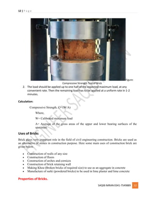


![62 | P a g e
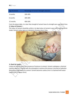
SAQIB IMRAN 0341-7549889 62
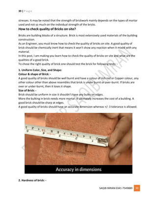
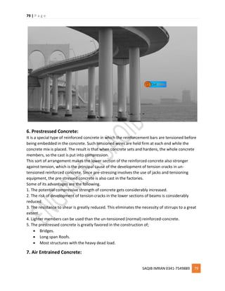
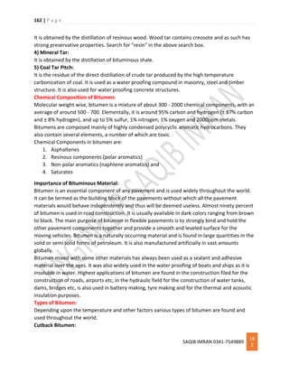
Excessive clay / Silt:-
Presence of clay in Sand makes the sand cohesive, the good quality of sand should have less
percentage of clay in it.
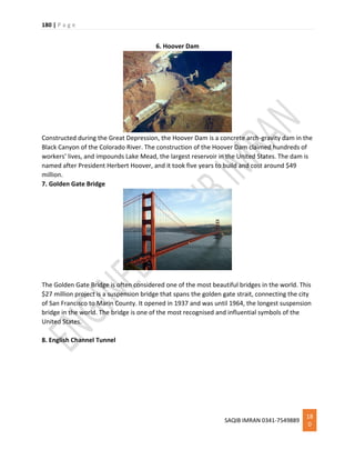
Presence of excessive clay can be determined in two ways:-
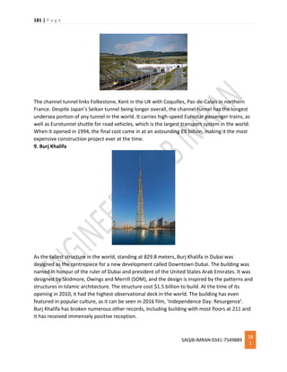
1. For testing presence of clay in the sand, take a glassful of water and add some sand to it.
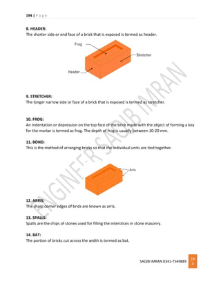
Shake it vigorously and allow the sand to settle. Check whether an apparent layer is
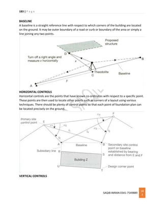
formed on the sand. A good quality of sand should have less than 8% of clay in it.
2. Hold some dry sand and drop it. If the Sand adheres to your palm, then it has Clay.
Presence of Organic Impurities in Sand: -
For detecting the presence of Organic impurities in fine aggregate. Take a Sample of sand and
add it in Sodium Hydroxide [NaOH] Solution, Stir the solution for few minutes, if the color of
solution changes to brown, then the sand has organic impurities which are not suitable for
construction. Good quality of sand shows lighter color when it is mixed with NaOH solution.
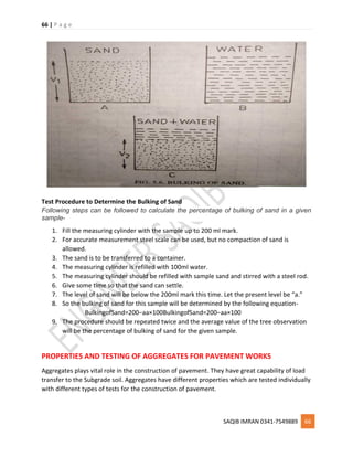
Presence of Excessive moisture content / Bulking of Sand: -
Presence of excessive moisture content in sand causes increase in the volume of sand. Fine
Aggregate Which contains more than 5% of moisture content in its volume is not suitable for
construction purposes.
For accurate conclusions, fineness modulus test and silt content by weight are suggested for
large projects
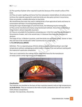
What is Bulking of Sand | Its Classification & How to Calculate it?
Sand is an important construction material of natural origin, mixed with cement and lime,
millions of tons of sands are used every month for construction as mortars, plasters, and
concrete.
The term sand is used for rock particles that range in grain size between 2 mm and 1/16 mm. In
composition, they are predominantly an oxide of silica SiO2.
Mineralogically, they consist mostly of broken grains of mineral Quartz (SiO2) produced as a
result of the breakdown of sandstones and similar rocks.
We will discuss below in details Classification and Bulking of Sand. So Let’s move on:
Classification of Sand.
Sands are classified variously on the basis of their mode of origin, their composition, and their
grain size.
Classification of Sands according to the mode of origin:
According to the mode of origin, sands are of three types, namely, pit sands, stream
sands and marine sands.](https://image.slidesharecdn.com/materialsmethodsofconstruction-ce145pdf-190108023941/85/Materials-Methods-of-Construction-CE145-62-320.jpg)

![88 | P a g e
SAQIB IMRAN 0341-7549889 88
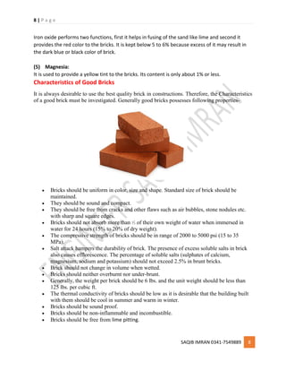
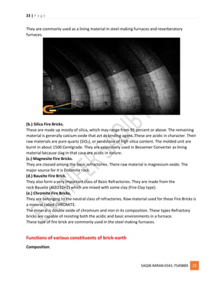
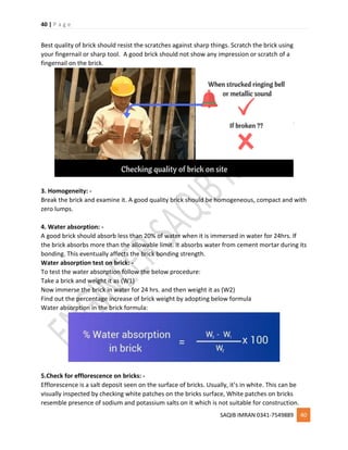
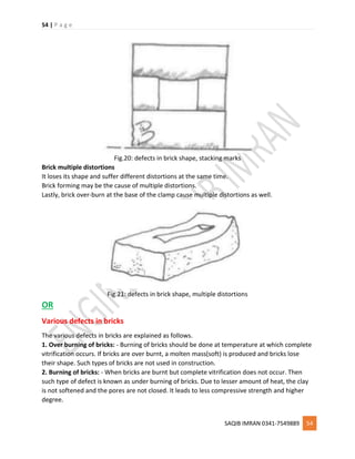
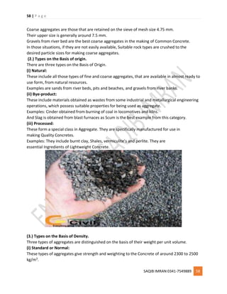
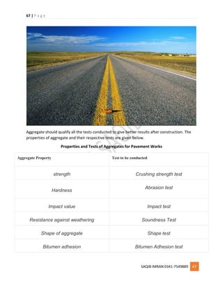
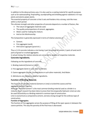
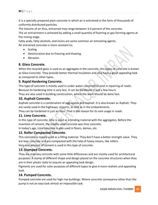
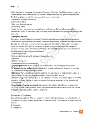
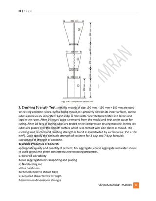
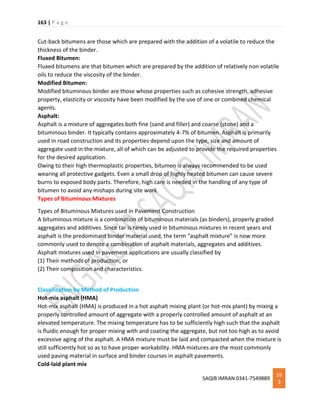
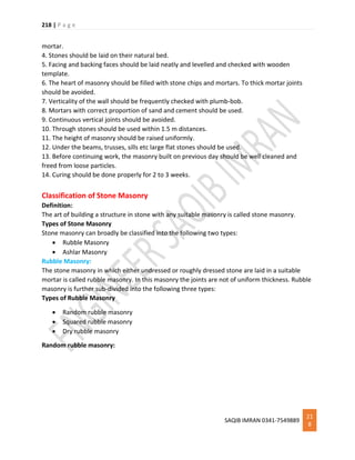
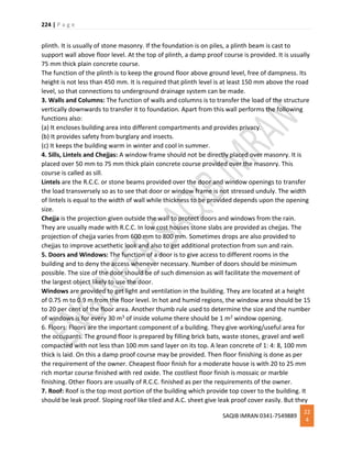
2. Compaction Factor Test: This is another test to identify the workability of concrete. This
test is conducted in the laboratory. The test equipment consists of two hoppers and a cylinder
fixed to a stand, the dimensions and the distances between the three vessels being
standardized. Vessel A and B are having hinged bottoms whereas cylinder C is having fixed
bottom. [Ref. Fig. 3.4] Top vessel A is filled with the concrete to be tested. As soon as it is filled,
the hinged door is opened. Concrete is collected in vessel B. Then the hinged door of B is
opened to collect concrete in cylinder C. The concrete in cylinder C is weighted. Let it be W1.
Now cylinder is again filled with the sample of concrete in 50 mm layers, which is compacted by
ramming and vibrating. Then the weight of compacted concrete is determined. Let this weight
be W2. The ratio W1/W2 is termed as compaction factor. The specified values of compaction
factor for different works are already listed in Table 3.2.](https://image.slidesharecdn.com/materialsmethodsofconstruction-ce145pdf-190108023941/85/Materials-Methods-of-Construction-CE145-88-320.jpg)

![93 | P a g e
SAQIB IMRAN 0341-7549889 93
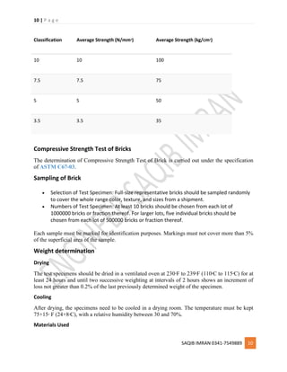
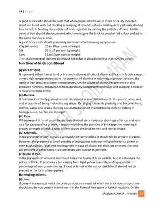
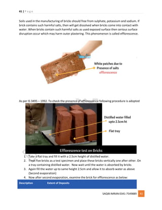
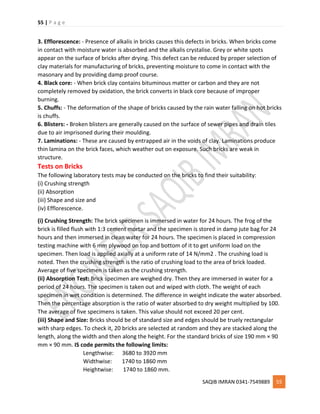
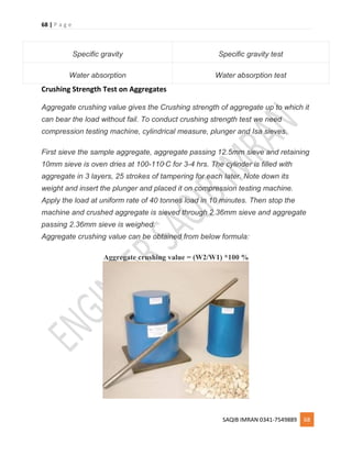
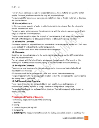
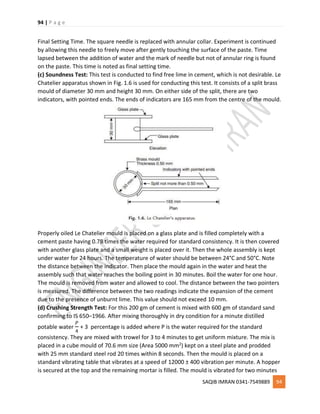
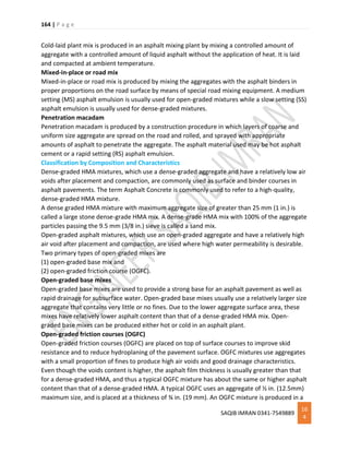
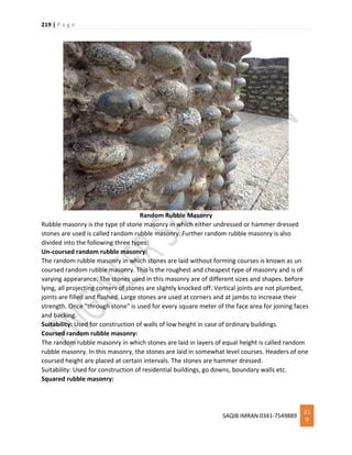
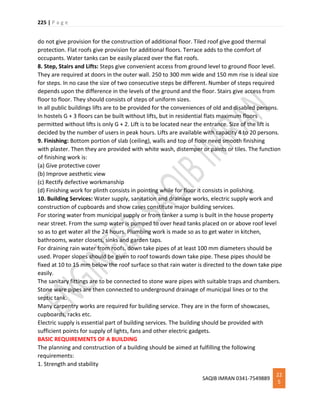
properties of cement. Initial setting time is the time taken by the cement from adding of water
to the starting of losing its plasticity. Final setting time is the time lapsed from adding of the
water to complete loss of plasticity. Vicat apparatus is used for finding the setting times [Ref.
Fig. 1.5]. Vicat apparatus consists of a movable rod to which any one of the three needles
shown in figure can be attached. An indicator is attached to the movable rod. A vicat mould is
associated with this apparatus which is in the form of split cylinder.
Before finding initial and final setting time it is necessary to determine water to be added to get
standard consistency. For this 300 gms of cement is mixed with about 30% water and cement
paste prepared is filled in the mould which rests on non porous plate. The plunger is attached
to the movable rod of vicat apparatus and gently lowered to touch the paste in the mould. Then
the plunger is allowed to move freely. If the penetration is 5 mm to 7 mm from the bottom of
the mould, then cement is having standard consistency. If not, experiment is repeated with
different proportion of water fill water required for standard consistency is found. Then the
tests for initial and final setting times can be carried out as explained below:
Initial Setting Time: 300 gms of cement is thoroughly mixed with 0.85 times the water for
standard consistency and vicat mould is completely filled and top surface is levelled. 1 mm
square needle is fixed to the rod and gently placed over the paste. Then it is freely allowed to
penetrate. In the beginning the needle penetrates the paste completely. As time lapses the
paste start losing its plasticity and offers resistance to penetration. When needle can penetrate
up to 5 to 7 mm above bottom of the paste experiment is stopped and time lapsed between
the addition of water and end if the experiment is noted as initial setting time.](https://image.slidesharecdn.com/materialsmethodsofconstruction-ce145pdf-190108023941/85/Materials-Methods-of-Construction-CE145-93-320.jpg)


![115 | P a g e
SAQIB IMRAN 0341-7549889
11
5
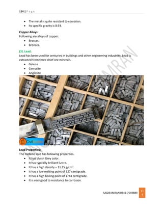
Lead Alloys:
In general, lead doesn’t form many alloys. Its alloying capacity is limited because of its low
melting point. Following are more important alloys of lead.
Solder
Terne plate
Type metal
Bearing metal
(4). Zinc:
Zinc is another non ferrous metal. The chief ore mineral of zinc is sulfide called sphalerite.
Smithsonite, Zincite (ZnO) and Calamine (ZnCO3) are other common zinc minerals.
Zinc Properties:
Following are some important properties of Zinc.
It is whitish and has bright lustre.
It has a density of 7.14 g/ml.
Its melting point is 419 centigrade and boiling point is 907 centigrade.
It has a tensile strength of 700-1400 kg/cm2.
Commercial zinc (spelter) is easily attacked by acids.
Zinc surface is covered by a dull basic zinc carbonate in moist air.
(5). Nickel:
Nickel was first discovered in 1750. It is manufactured from its sulfide ore
named pentlandite [NiFe(S)].
The ore is first concentrated by froth flotation process and then roasted and smelted like
other non ferrous metals.](https://image.slidesharecdn.com/materialsmethodsofconstruction-ce145pdf-190108023941/85/Materials-Methods-of-Construction-CE145-115-320.jpg)


![141 | P a g e
SAQIB IMRAN 0341-7549889
14
1
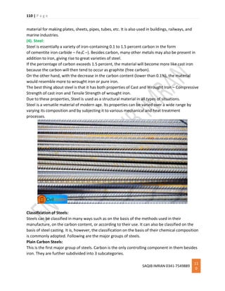
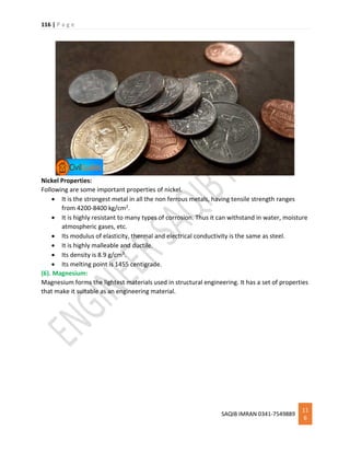
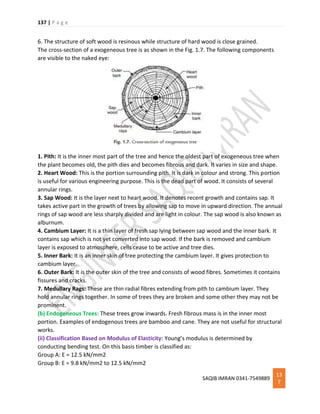
(b) Shakes: The shakes are cracks in the timber which appear due to excessive heat, frost or
twisting due to wind during the growth of a tree. Depending upon the shape and the positions
shakes can be classified as star shake, cup shake, ring shakes and heart shakes [Ref. Fig. 1.10].
(c) Wind Cracks: These are the cracks on the outside of a log due to the shrinkage of the
exterior surface. They appear as shown in Fig. 1.11.
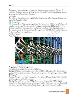
(d) Upsets: Figure 1.12 shows a typical upset in a timber. This type of defect is due to excessive
compression in the tree when it was young. Upset is an injury by crushing. This is also known as
rupture.
(ii) Defects due to Defective Seasoning and Conversion: If seasoning is not uniform, the
converted timber may warp and twist in various directions. Sometimes honey combining and
even cracks appear. This type of defects are more susceptible in case of kiln seasoning.
In the process of converting timber to commercial sizes and shapes the following types of
defects are likely to airse: chip marks, torn grain etc.
(iii) Defects due to Fungi and Insects Attack: Fungi are minute microscopic plant organism.](https://image.slidesharecdn.com/materialsmethodsofconstruction-ce145pdf-190108023941/85/Materials-Methods-of-Construction-CE145-141-320.jpg)

![146 | P a g e
SAQIB IMRAN 0341-7549889
14
6
3.Bilk
4.Deal
5.Batten
6.Plank
7.Board
8.Scantline
9.Pole
Asbestos
Asbestos is a general name for several varieties of fibrous minerals which are available in
nature. But presently, most of the commercial asbestos produced is ‘chriotile’
[Mg6SiO11(OH)6.H2O].
Properties of Asbestos
1. It is flexible, soft and non-porous.
2. It is fire proof and acid proof material.
3. It is a good insulator of heat and electricity.
4. When it is mixed with cement and water, it retains shape firmly.
5. Its colour is brown or grey.
6. It can be cut into pieces or can be drilled.
7. It possesses high tensile strength in the direction of its fibres.
8. Its specific gravity is 3.10.
Uses of Asbestos
1. Asbestos cement sheets are the cheapest roofing materials.
2. Asbestos cement pipes are used as down take pipes of rain water from the roof.
3. With bitumen it forms good damp proof layer.
4. It is used for preparing fire proof ropes and clothes.
5. It is used as covering material for fuse and electric switch boxes.
6. It is useful for insulating boilers,
Paints
Paints are applied on the surfaces of timber, metals and plastered surfaces as a protective layer and at
the same time to get pleasant appearance. Paints are applied in liquid form and after sometime the
volatile constituent evaporates and hardened coating acts as a protective layer.
Constituents of Paint
The essential constituents of paints are:
1. Base 2. A vehicle 3. A pigment 4. A drier and 5. A thinner.
1. Bases: It is a principal constituent of paint. It also possesses the binding properties. It forms
an opaque coating. Commonly used bases for paints are white lead, red lead, zinc oxide, iron
oxide, titanium white, aluminium powder and lithophone. A lead paint is suitable for painting
iron and steel works, as it sticks to them well. However it is affected by atmosphere action
and hence should not be used as final coat. While zinc forms good base but is costly.](https://image.slidesharecdn.com/materialsmethodsofconstruction-ce145pdf-190108023941/85/Materials-Methods-of-Construction-CE145-146-320.jpg)

![155 | P a g e
SAQIB IMRAN 0341-7549889
15
5
=
W2 − W1
W4 − W1
.
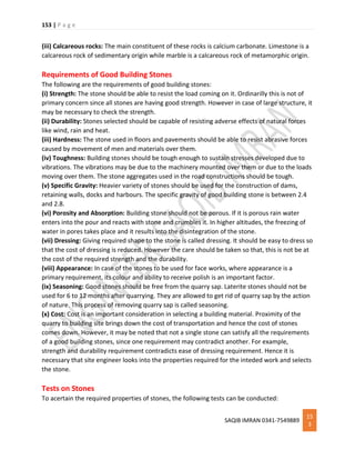
(iii) Abrasion Test: This test is carried out on stones which are used as aggregates for road
construction. The test result indicate the suitability of stones against the grinding action
under traffic. Any one of the following test may be conducted to find out the suitability of
aggregates:
(i) Los Angeles abrasion test
(ii) Deval abrasion test
(iii) Dorry’s abrasion test.
However Los Angeles abrasion test is preferred since these test results are having good
correlation with the performance of the pavements.
The Los Angeles apparatus [Fig. 1.1] consists of a hollow cylinder 0.7 m inside diameter and
0.5 m long with both ends closed. It is mounted on a frame so that it can be rotated about
horizontal axis. IS code has standardised the test procedure for different gradation of specimen.
Along with specified weight of specimen a specified number of cast iron balls of 48 mm
diameter are placed in the cylinder
Then the cylinder is rotated at a speed of 30 to 33 rpm for specified number of times (500 to
1000). Then the aggregate is removed and sieved on 1.7 mm. IS sieve. The weight of aggregate
passing is found. Then Los Angeles value is found as
=
Weight of aggregate passing through sieve
Original weight
x 100.
The following values are recommended for road works:
For bituminous mixes – 30%
For base course – 50%](https://image.slidesharecdn.com/materialsmethodsofconstruction-ce145pdf-190108023941/85/Materials-Methods-of-Construction-CE145-155-320.jpg)


![173 | P a g e
SAQIB IMRAN 0341-7549889
17
3
1. Penetration Test on Bitumen
The penetration test is one of the oldest and most commonly used tests on asphalt cements or
residues from distillation of asphalt cutbacks or emulsions. The standardized procedure for this
test can be found in ASTM D5 [ASTM, 2001]. It is an empirical test that measures the
consistency (hardness) of an asphalt at a specified test condition.
Procedure of Penetration Test on Bitumen:
In the standard test condition, a standard needle of a total load of 100 g is applied to the
surface of an asphalt or Liquid bitumen sample at a temperature of 25 °C for 5 seconds. The
amount of penetration of the needle at the end of 5 seconds is measured in units of 0.1 mm (or
penetration unit). A softer asphalt will have a higher penetration, while a harder asphalt will
have a lower penetration. Other test conditions that have been used include
1. 0 °C, 200 g, 60 sec., and
2. 46 °C, 50 g, 5 sec.
The penetration test can be used to designate grades of asphalt cement, and to measure
changes in hardness due to age hardening or changes in temperature.
2. Flash Point Test on asphalt:
The flash point test determines the temperature to which an asphalt can be safely heated in the
presence of an open flame. The test is performed by heating an asphalt sample in an open cup
at a specified rate and determining the temperature at which a small flame passing over the
surface of the cup will cause the vapors from the asphalt sample temporarily to ignite or flash.
The commonly used flash point test methods include
The Cleveland Open Cup (ASTM D92)
Tag Open Cup (ASTM D1310).
The Cleveland Open-Cup method is used on asphalt cements or asphalts with relatively higher
flash points, while the Tag Open-Cup method is used on cutback asphalts or asphalts with flash
points of less than 79 °C. Minimum flash point requirements are included in the specifications
for asphalt cements for safety reasons. Flash point tests can also be used to detect
contaminating materialssuch as gasoline or kerosine in an asphalt cement. Contamination of an
asphalt cement by such materials can be indicated by a substantial drop in flash point.
When the flash point test is used to detect contaminating materials, the Pensky-Martens Closed
Tester method (ASTM D93), which tends to give more indicative results, is normally used. In
recent years, the flash point test results have been related to the hardening potential of
asphalt. An asphalt with a high flash point is more likely to have a lower hardening potential in
the field.
3. Solubility Test on asphalt bitumen
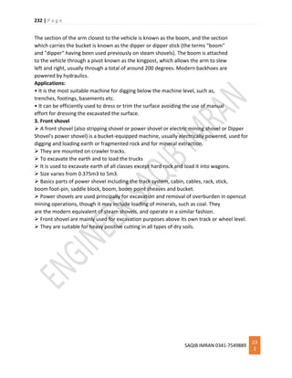
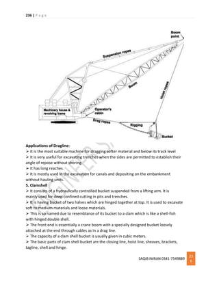
Asphalt consists primarily of bitumens, which are high-molecular-weight hydrocarbons soluble
in carbon disulfide. The bitumen content of a bituminous material is measured by means of its
solubility in carbon disulfide.
Procedure for Solubility test on Bitumen](https://image.slidesharecdn.com/materialsmethodsofconstruction-ce145pdf-190108023941/85/Materials-Methods-of-Construction-CE145-173-320.jpg)


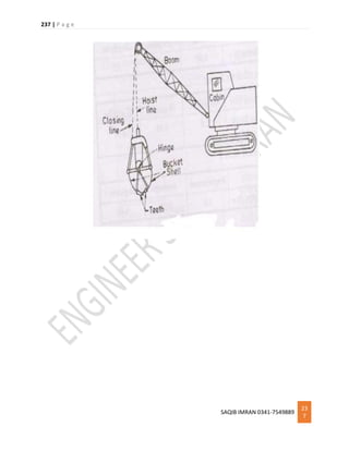
![221 | P a g e
SAQIB IMRAN 0341-7549889
22
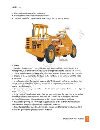
1
In this type of stone masonry stone blocks of same height in each course are used. Every stone
is fine tooled on all sides. Thickness of mortar is uniform through out. It is an expensive type of
stone masonry as it requires heavy labor and wastage of material while dressing. Satisfactory
bond can be obtained in this type of stone masonry.
Random coursed ashlar masonry:
This type of ashlar masonry consists of fine or coursed ashlar but the courses are of varying
thicknesses, depending upon the character of the building.
Rough tooled ashlar masonry:
This type of ashlar masonry the sides of the stones are rough tooled and dressed with chisels.
Thickness of joints is uniform, which does not exceed 6mm.
Rock or quarry faced ashlar masonry:
This type of ashlar masonry is similar to rough tooled type except that there is chisel-drafted
margin left rough on the face which is known as quarry faced.
Chamfered ashlar masonry:
It is similar to quarry faced except that the edges are beveled or chamfered to 450 for depth of
2.5 cm or more.
Block-in course masonry:
It is the name given to a class of ashlar masonry which occupies an intermediate place between
rubble and ashlars. The stones are all squared and properly dressed. It resembles to coursed
rubble masonry or rough tooled ashlar masonry.
Ashlar facing:
Ashlar facing is the best type of ashlars masonry. Since this is type of masonry is very expensive,
it is not commonly used throughout the whole thickness of the wall, except in works of great
importance and strength. For economy the facing is built in ashlars and the rest in rubble.
OR
1. Rubble Masonry: In this type of constructions stones of irregular sizes and shapes are used.
To remove sharp shapes they may be hammered. The rubble masonry may be coursed or
uncoursed [Fig. 8.1 and 8.2]. In uncoursed rubble masonry the wall is brought to level at
every 300 mm to 500 mm. The mortar consumed in these construction is more. Course
rubble masonry is used for the construction of public and residential buildings. Uncoursed
rubble masonry is used for the construction of foundations, compound walls, garages, labour
quarters etc. A skilled mason may arrange the facing stones in polygonal shapes to improve
the aesthetic of the wall.](https://image.slidesharecdn.com/materialsmethodsofconstruction-ce145pdf-190108023941/85/Materials-Methods-of-Construction-CE145-221-320.jpg)


This document provides a detailed classification of different types of bricks based on various factors such as quality, manufacturing process, raw materials, intended use, weather resistance, and shape. It identifies several classes of bricks including first, second, and third class bricks based on quality standards. It also discusses different types of bricks such as burnt clay bricks, fly ash clay bricks, concrete bricks, sand-lime bricks, and firebricks which vary according to their raw material composition. Bricks are further classified based on factors like intended location of use, weather resistance requirements, and special shapes required for applications like rounded edges, air circulation, drainage, and wall capping.


![Report on a building material [ bricks]](https://cdn.slidesharecdn.com/ss_thumbnails/reportonabuildingmaterialbricks-170303122959-thumbnail.jpg?width=640&height=640&fit=bounds)


![Getting Started with Apache Spark: Big Data Made Simple [Free Meetup]](https://cdn.slidesharecdn.com/ss_thumbnails/apachesparkgettingstarted-260203175547-8361bcc3-thumbnail.jpg?width=640&height=640&fit=bounds)


