Download as PDF, PPTX

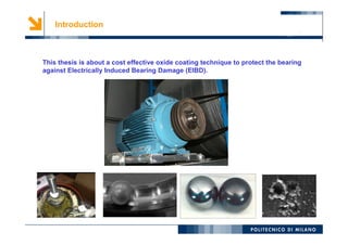
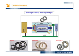
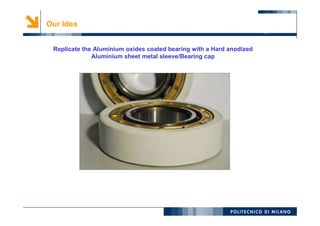
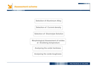
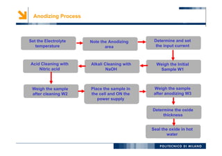
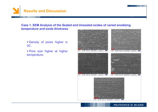
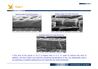
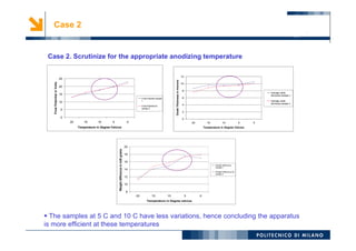
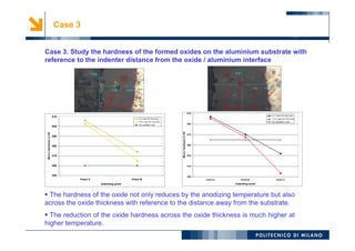
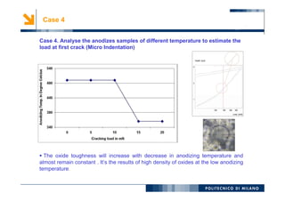
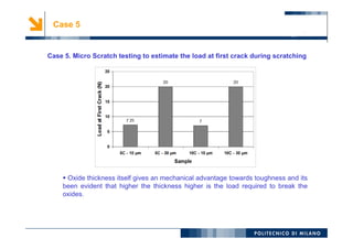
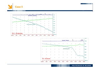
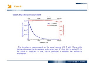

This thesis assesses anodic aluminium oxide coatings as an alternative solution to spark erosion damage of bearings. The current solution of using insulated or ceramic bearings is expensive. Anodizing aluminium in different electrolyte solutions at varying temperatures and current densities was tested to optimize the oxide thickness, hardness, and toughness. Testing showed oxides formed at lower temperatures of 5-10°C had higher density, smaller pores, greater hardness even at increased thickness from the substrate, and required higher loads to cause cracking than oxides formed at higher temperatures. Impedance measurements also indicated the optimized coating maintained sufficient electrical resistance. Further work is needed to improve toughness through sealing and determine electrical properties and testing on prototypes.


![Ceramic coating [tio2 zro2] on aluminium 6061 t6 for anti](https://cdn.slidesharecdn.com/ss_thumbnails/ceramiccoatingtio2-zro2onaluminium6061t6foranti-140821045215-phpapp01-thumbnail.jpg?width=640&height=640&fit=bounds)
