Mammography Physics provides an overview of mammography physics concepts including:
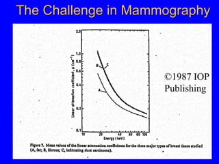
1) Why special attention is paid to mammography physics given breast cancer rates and false positives/negatives.
2) Radiation risk/benefit issues and dose limits for screening mammography.
3) Physical principles of full field digital mammography (FFDM) including detector types, computed radiography, and slit scanning technology.
4) Technical details of digital breast tomosynthesis (DBT) such as acquisition parameters, reconstruction, and dose for the Hologic Selenia Dimensions system.