This document defines the mission statement for a proposed interstellar probe called "La Pinta" to study the Alpha Centauri system. It provides an overview of the state of knowledge on interstellar travel based on historical spacecraft concepts. The document outlines the mission objectives, operational concept, systems requirements, and risks. The proposed mission would utilize an ion engine or solar sail propulsion system to travel to Alpha Centauri over several decades, carrying instruments to characterize any exoplanets and the interstellar medium. Defining the mission requirements is the first step to further develop the concept and assess feasibility for a future interstellar exploration mission.


![Chapter 1. Introduction 2
However, according with ESA standars the planning of a project is structured into
different sequential phases. For both of them the start of a phase is generally subject
to the passing of a milestone. Although each phase is a part of a sequential logic, the
start of the next phase can be decided before all the tasks of the current phase are fully
completed. In this case, induced risks have to be clearly identified. Reviews are used as
control gates in the full system life cycle to determine whether the system development
process should continue from one phase to the next, or what modifications may be
required.
The overlapping of the activities of different phases does not prevent responsibility for
the phases from being assigned to different lead actors. The model philosophy shall be
defined as early as possible with respect to project phasing and planning, taking into
account available resources and technological risks. ESA standards split the mission
phases into the following ones,
• Phase 0 – Mission Analysis/Needs Identification
• Phase A – Feasibility
• Phase B – Preliminary Definition
• Phase C – Detailed Definition
• Phase D – Production/Ground Qualification Testing
• Phase E – Utilisation
• Phase F – Disposal Phase
In this document only first two phases of NASA standards or first one from ESA is going
to be developed. The rest of mission phases definitions can be consulted in [7] and [16].
1.1.1 Conceptual Study or Needs Identification
The phase starts when a person or group petitions have an idea or plan. The proposal
is studied and evaluated for merit, and, if accepted, the task of screening feasibility is
delegated to a department or center (robotic, solar system, etc...)
Prior to Phase A, the following activities typically take place: Headquarters establishes a
Science Working Group (SWG). The SWG develops the science goals and requirements,
and prepares a preliminary scientific conception of the mission. Based on the high-level
concept and the work of the SWG, a scientific document called the Announcement of
Opportunity (AO) is sent out by Headquarters to individual scientists at universities,
space centers, and science organizations. The AO defines the existing concept of the
mission and the scientific opportunities, goals, requirements, and system concepts. In
the case of this thesis the tutor plays the role of Headquartes and the AO is defined in
the proposal of the ‘Trabajo de fin de M´aster’ (TFM).
All proposals for new experiments are reviewed for science merit as related to the goal
of the mission. Mass, power consumption, science return, safety, and ability to support
the mission from the ”home institution” are among key criteria. A library of launch
possibilities that becomes available to the project may be developed too.](https://image.slidesharecdn.com/be749a14-fecc-453e-8f55-adade5c30f38-161020132348/85/main-14-320.jpg)


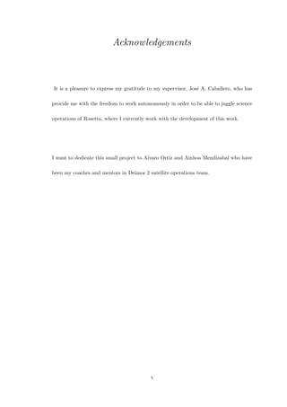
![Chapter 3. Mission Overview and Operational concept 12
Acceleration phase Cruise phase Min. data return
0.01 g for 5 years 0.05 c for 84 years 94 years
0.01 g for 10 years 0.1 c for 42 years 57 years
0.1 g for 1 year 0.1 c for 42 years 48 years
0.1 g for 5 years 0.5 c for 8 years 18 years
0.5 g for 1 year 0.5 c for 8 years 14 years
Table 3.2: Linear mission analysis to effective α Cen.
One is quickly led to some simple conclusions about practical requirements for acceler-
ation (0.01–1 g), mission velocity (0.1–0.5c) and mission duration (10–100 years).
An ideal mission profile would be one that employed 0.1 g acceleration for a few years
up to 0.3c resulting in total mission duration of 50 years. Conventional thinking, e.g.
in Ref.[1] about future interstellar missions is that they are likely to be one of two types:
• Type I: A short 50-year mission using high exhaust velocity engines to accelerate
to a moderate fraction of the speed of light, 0.1–0.3c, completing the mission
within the lifetime of designers.Identification and characterisation of the intended
mission,
• Type II: A long 100–1,000 year mission using low exhaust velocity engines, com-
pleting the mission duration over several generations of designers.
It is generally believed that a Type I mission would require a large technology jump,
but a Type II mission would require only a moderate jump, except perhaps with the
environmental lifetime requirements.
Now all the above analysis is based upon linear theory, but in reality rockets are governed
by the ideal rocket equation which is logarithmic that means values have a ∆ error.
Anycase results are quite similar and the total mission duration would be around 50
years.
Energy required calculation may be simplified considering that the energy needed to
impart a vehicle to produce kinetic energy for forward momentum, assuming 100%
conversion efficiency. Considering the case of a vehicle accelerated for 0.1 g up to 0.3
c, once the kinetic energy is calculated the power required is obtained by dividing the
energy by the number of seconds during the boost phase if the propellant mass is assumed
to dominate the total mass of the vehicle. The results is that the minimum power to
push a 1-ton vehicle to 1/3 of light speed over a period of 3 years is around 50 GW. For
the same speed a 100,000-ton vehicle would require around 5 PW of power.
From this analysis some data to assess the suitability of various propulsion schemes can
be produced and it is summarized in the next table 3.3. It is important to consider that
the balance between acceleration and boost duration is limited to the speed of light.
All data calculated during this section will be used in the propulsion chapter 4.1.1 to
the propulsion method choice and total mass calculations.](https://image.slidesharecdn.com/be749a14-fecc-453e-8f55-adade5c30f38-161020132348/85/main-24-320.jpg)
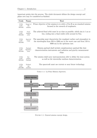
![Chapter 3. Mission Overview and Operational concept 13
Description Mission data
Initial acceleration (g) 0.1
Cruise velocity (km/s) 30,937 (10.3% c)
Fraction light speed ∼ 1/10
Boost duration (years) 1
Boost distance (light years) 0.051
Cruise duration (years) 41
Minimum energy (J) 4.8 x 10¹⁸
Minimum power (GW) 150
Table 3.3: Approximate mission profile for a 10-ton flyby interstellar probe α Cen.
3.2.2 Environmental analysis overview
As showed in the previous chapter the preliminar calculated lifetime for the mission is
41 years of cruise and let’s say 9 years of nominal, considering all the mission risks. So
all the subsystems will be exposed for 50 years of space radiation, very high and very
low temperatures and a high variety of micro particles and other small objects.
The initial radiation analysis is usually performed though standard tools like SPENVIS,
from ESA. To see how the program works the Ref [20] goes directly to the online software.
This programm has been created with the best radiation models we have now, but
unfortunately it doesn’t include far orbits from the Earth and 50 years missions so the
model has been extrapolated to the case of the ‘La Pinta’.
A rough estimation would be a Total Ionizing Dose (TID) of 3 x 10⁴ Krads without any
kind of protection and less than 10 Krads (the standard TID protection for commercial
space components) for 12 cm of aluminium shielding protection.
3.2.2.1 Local Interestellar Medium
The local interstellar medium properties have been studied in Ref [11] though there is
no in-situ observational data as no probe has been able to traverse the heliopause and
measure the desired properties directly. We do not have sufficient knowledge of the
various cloud distribution in the local interstellar neighbourhood viz the ionisation state
and the dust particle or grain density. Estimation of these parameters are crucial for a
successful interstellar probe. Methods to eradicate the effects of interstellar dust grain
on the spacecraft is a key aspect of this mission. For this reason the dust experiment
characterization is described in chapter 4.1.6.
3.2.2.2 Collision avoidance protocol
Due to the high amount of space junk around the Earth protocols of collission avoidance
plans are more than enough for the ‘La Pinta’ mission. The only difference is that
NORAD is not detecting high distance objects yet. A NavCam (image adquisitions
though payload cameras to use for navigation purposes) protocol shall be implemented
into the instrument planning to detect possible objects to intercept the mission orbit.](https://image.slidesharecdn.com/be749a14-fecc-453e-8f55-adade5c30f38-161020132348/85/main-25-320.jpg)

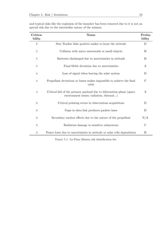
![Chapter 3. Mission Overview and Operational concept 15
1. Terrestrial planets
2. Giant planets
3. The stars
4. Minor objects
5. Dust
Secondary science objectives would be along the lines of:
• observations of solar system outer bodies
• measurements of the heliopause and interstellar medium
• measurements addressing gravitational issues
• spacecraft reliability with long duration missions
According with Table 3.5 a selection of detectors and instrumentation can be done with
the MO and the selected orbit. This is not a linear process and some iterations has
been done between the different related chapters. It is important to emphasise than the
description of the payload observations and
babab
3.4.2 Instrument Description
According with Table 3.5, and UCM-LAP-MO-003, UCM-LAP-MO-004 and UCM-
LAP-MO-005 the instrumentation shall be composed by a telescope with the maximum
resolution possible, an hyper spectral detector system composed by at least eight bands,
including RGB and NIR to cover the huge spectral range required in MO. The actual
state of the art for these kind of devices is very evolved due to they are commonly used
in the Earth Observation Missions.
Primary payload is composed as well for a Dust Analyser that would measure the num-
ber, mass, momentum and velocity distribution of dust grains in the environment on
the α Cen Bb system.
Finally, and as primary instrumentation an ion mass analyser equipped with a dust
collector, a primary ion gun, and an optical microscope for target characterization would
be fulfill the rest of MO. Dust from the near environment would be collected on a target.
The target would be then moved under a microscope where the positions of any dust
particles were determined. The dust particles would be then bombarded with pulses of
indium ions from the primary ion gun. The resulting secondary ions would be extracted
into the time-of-flight mass spectrometer.
Las two instruments have been derived from [15] and Rosetta instruments, COSIMA
and GIADA. They are widely validated after 12 years in orbit and two more years fully
operating, in spite of their complexity.](https://image.slidesharecdn.com/be749a14-fecc-453e-8f55-adade5c30f38-161020132348/85/main-27-320.jpg)


![Chapter 4. Systems 20
4.1.4 COMMS
To communicate in ranges of 1000 AU or more, efficient long range and low mass telecom-
munications techniques is a topic of advanced communication. In order to keep the
physical size of transmitter reasonable and limit the required transmitter power, an op-
tical downlink operating in near infrared with a 1 m diffractive primary can be selected.
The system requires integrated optical communications, attitude, guidance and control
in order to hold the pointing requirement. Moreover, there should also be very high
gain.The data from the experiments during interstellar flight will be returned to earth
at low data rates. This will also ensure that the contact with the probe is maintained.
Since the probe has to be fully autonomous,any problems with communication systems
due to degradation of transmitting equipment of faulty link analysis will have to be cor-
rected by making improvements in receiving equipment. Maintaining constant contact
will give time to implement any corrective measures in the receiving equipment.
The same solution of Buoy systems can be developed as an intermediate link, e.g. in
the surroundings of Pluto, but a deeper analysis may be performed to study their via-
bility. Although optical links seems to be part of science fiction books the true is some
companies like RUAG are developing satellite to satellite optical link communications
nowadays. That would up the amount of data being transmitted by 10 to 100 times what
state-of-the-art radio rigs can do, which would make interplanetary Internet roughly as
fast as a typical broadband connection on Earth. The constrain is some GAPs will be
produced during loses on the line of sight.
Secondary communication system shall be carried as part od the redundancy. X band
(8,4 GHz) with data rates of approximately 300 Mbps are actually used for planetary
communications. This data rate would determine the MPS PSF’s.
4.1.5 OBC
A probed mission to α Cen has to be designed with the Artificial Intelligence proto-
cols. As explained in section 3.4.4, some decisions that required reaction times shall be
calculated on board though protocols of auto learning with similar methods of google
car computer trained with deep learning (see Ref [22]). Although this point is vital for
the development of the project the author’s skills in this matter doesn’t afford to get
further.
4.1.6 Payload: EXOS (Exoplanet Observation System)
As explained before in chapter 3.4.2, three instruments make up the primary payload.
Ion mass and dust analyser have been explained briefly before. The telescope required
for this mission shall provide an acceptable resolution.
Comparing with Earth observation missions values of 600 km of swath is similar to the
low resolution satellites that are used for study the terrain, water distribution, etc... For
a distance of 1 au, according with Rayleigh criteria, it is necesary a telescope aperture
of 2,5 meters to obtain a ground sample distance (GSD) of 1 meter resulting a swath
of 312.5 km for a pixel size of 6 micras. The required number of pixels of the detector](https://image.slidesharecdn.com/be749a14-fecc-453e-8f55-adade5c30f38-161020132348/85/main-32-320.jpg)


![Appendix B
Satellite preliminar design
The following draws have been performed by a famous video game called ‘Kerbal Space
Program’ that is capable to design space missions with a pretty precision in maths and
engineering. For more information about it, see Ref[21].
Figure B.1: Preliminar design overview.
28](https://image.slidesharecdn.com/be749a14-fecc-453e-8f55-adade5c30f38-161020132348/85/main-40-320.jpg)

![Bibliography
[1] K. F. Long. Deep Space Propulsion: A Roadmap to Interstellar Flight . Springer,
December 2011.
[2] P. Gilster. Centauri Dreams: Imagining and Planning Interstellar Exploration.
Copernicus, October 2004.
[3] M. Perryman. The Exoplanet Handbook. Cambridge University Press, May 2011.
[4] G. F. Bignami, A. Sommariva. A Scenario for Interstellar Exploration and Its
Financing. Springer, April 2013.
[5] J. L. Linsky,V. V. Izmodenov,E. M¨obius,R. von Steiger. From the Outer Heliosphere
to the Local Bubble Comparison of New Observations with Theory. Previously
published in Space Science Reviews Volume 143, Issues 1–4, 2009 Springer, 2009.
[6] G. L. Matloff, L. Johnson,C. Bangs. Living off the Land in Space; Green Roads to
the Cosmos. Copernicus, 2007.
—————————————————Manuals———————————————
[7] European Space Agency Standards (ECSS). Project Phasing and Planning. Mission
Operations Concept ECSS-M-30A, 6th June 2011.
[8] NASA-ESA document. Laser Interferometer Space Antenna (LISA) Operations
Concept. LISA-OPS-RP-0001, March 24, 2009.
[9] NASA. 2015 NASA Technology Roadmaps. Draft, May 2015.
30](https://image.slidesharecdn.com/be749a14-fecc-453e-8f55-adade5c30f38-161020132348/85/main-42-320.jpg)
![Bibliography 31
—————————————————Articles———————————————
[10] M. Schmidt, F. Dreger. Mission Operations Concept and Ground Segment System
Architecture relevant to the Instrument Operations of the INTEGRAL Mission.
INT-SYS-MIS-TN-0001-OGI, 1998.
[11] R. F. Wimmer-Schweingruber,Ralph McNutt, N. A. Schwadron, P. C. Frisch,
M. Gruntman, P. Wurz, E.Valtonen. Interstellar heliospheric probe/heliospheric
boundary explorer mission, a mission to the outermost boundaries of the solar sys-
tem. Exp Astron (2009) 24:9–46 DOI 10.1007/s10686-008-9134-5, March,2009.
[12] S. Pizzurro, C. Circi. Optimal Trajectories for Solar Bow Shock Mission. ISSN
0010-9525, Cosmic Research 2012, Vol.50, No.6, pp.459-465, February 2012.
[13] Xiangyuan Zeng,K. T. Alfriend, J. Li, S. R. Vadali. Optimal Solar Sail Trajectory
Analysis for Interstellar Missions. American Astronautical Society 2014, 59:502–516
DOI 10.1007/s40295-014-0008-y, July 2014.
[14] D.J. McComas, F. Allegrini, P. Bochsler, M. Bzowski, M. Collier, H. Fahr, H.
Fichtner, P. Frisch, H.O. Funsten, S.A. Fuselier, G. Gloeckler, M. Gruntman, V.
Izmodenov, P. Knappenberger, M. Lee, S. Livi, D. Mitchell, E. M¨obius, T. Moore,
S. Pope, D. Reisenfeld, E. Roelof, J. Scherrer, N. Schwadron, R. Tyler, M. Wieser,
M. Witte, P. Wurz, G. Zank. IBEX—Interstellar Boundary Explorer . Space Sci
Rev (2009) 146: 11–33 DOI 10.1007/s11214-009-9499-4,Abril 2009.
[15] S.A. Fuselier, P. Bochsler, D. Chornay, G. Clark, G.B. Crew, G. Dunn, S. Ellis,
T. Friedmann · H.O. Funsten · A.G. Ghielmetti · J. Googins, M.S. Granoff, J.W.
Hamilton · J. Hanley, D. Heirtzler, E. Hertzberg, D. Isaac, B. King, U. Knauss, H.
Kucharek, F. Kudirka, S. Livi, J. Lobell, S. Longworth, K. Mashburn, D.J. McCo-
mas, E. M¨obius, A.S. Moore, T.E. Moore, R.J. Nemanich, J. Nolin, M. O’Neal, D.
Piazza, L. Peterson, S.E. Pope, P. Rosmarynowski, L.A. Saul, J.R. Scherrer, j.A.
Scheer, C. Schlemm, N.A. Schwadron , C. Tillier, S. Turco, J. Tyler, M. Vosbury,
M. Wieser, P. Wurz, S. Zaffke The IBEX-Lo Sensor . Space Sci Rev (2009) 146:
117–147 DOI 10.1007/s11214-009-9495-8,May 2009.](https://image.slidesharecdn.com/be749a14-fecc-453e-8f55-adade5c30f38-161020132348/85/main-43-320.jpg)
![Bibliography 32
————————————————–Webpages——————————————-
[16] http://www2.jpl.nasa.gov/basics/bsf7-1.php.
[17] http://www.esa.int/Our_Activities/Space_Science/Rosetta/Europe_s_
comet_chaser.
[18] https://www.linkedin.com/pulse/overview-space-missions-dedicated-portrayal-mar%
C3%ADn-yaseli-de-la-parra?trk=prof-post.
[19] http://exoplanet.eu/catalog/alf_cen_b_b/.
[20] https://www.spenvis.oma.be/.
[21] https://kerbalspaceprogram.com/en/.
[22] http://www.technologyreview.com/news/533936/
ces-2015-nvidia-demos-a-car-computer-trained-with-deep-learning/.](https://image.slidesharecdn.com/be749a14-fecc-453e-8f55-adade5c30f38-161020132348/85/main-44-320.jpg)


![[Sapienza] Development of the Flight Dynamics Model of a Flying Wing Aircraft](https://cdn.slidesharecdn.com/ss_thumbnails/355a5afb-e186-4fcb-b8a5-c15a5650ca6a-160412194308-thumbnail.jpg?width=640&height=640&fit=bounds)


![1010 woolsey[1]](https://cdn.slidesharecdn.com/ss_thumbnails/qtowjnbcsb6xtwzj83vj-signature-3e49a9720aafd161ec5213fc5cb0fac76e0a38578f2089fb876ad1cc6de4bad4-poli-140825181335-phpapp01-thumbnail.jpg?width=640&height=640&fit=bounds)


