Downloaded 11 times


![List of Figures
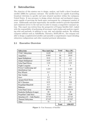
1 Cost Summary of Satellite . . . . . . . . . . . . . . . . . . . . . . . . 9
2 Power Summary of Satellite . . . . . . . . . . . . . . . . . . . . . . . 10
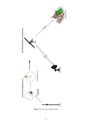
3 Concept of Operations . . . . . . . . . . . . . . . . . . . . . . . . . . 15
4 Orbit Trade Study . . . . . . . . . . . . . . . . . . . . . . . . . . . . 17
5 LEO . . . . . . . . . . . . . . . . . . . . . . . . . . . . . . . . . . . . 18
6 GTO . . . . . . . . . . . . . . . . . . . . . . . . . . . . . . . . . . . . 18
7 Launch Characteristics . . . . . . . . . . . . . . . . . . . . . . . . . . 19
8 Spot Beam vs. Broad Beam[12] . . . . . . . . . . . . . . . . . . . . . 20
9 Parabolic Reflector Dish . . . . . . . . . . . . . . . . . . . . . . . . . 21
10 Shaped Reflector Antenna . . . . . . . . . . . . . . . . . . . . . . . . 21
11 Range of Frequency Bands . . . . . . . . . . . . . . . . . . . . . . . . 22
12 Cost vs. Availability . . . . . . . . . . . . . . . . . . . . . . . . . . . 23
13 Link Budget . . . . . . . . . . . . . . . . . . . . . . . . . . . . . . . . 24
14 Amplifier Trade Study[23] . . . . . . . . . . . . . . . . . . . . . . . . 25
15 TWTA Amplifier [10] . . . . . . . . . . . . . . . . . . . . . . . . . . . 26
16 Polarization Architecture . . . . . . . . . . . . . . . . . . . . . . . . . 26
17 Static Stress Analysis . . . . . . . . . . . . . . . . . . . . . . . . . . . 28
18 Deformation . . . . . . . . . . . . . . . . . . . . . . . . . . . . . . . . 29
19 Side View of Satellite Structure . . . . . . . . . . . . . . . . . . . . . 30
20 Structure Mass Summary . . . . . . . . . . . . . . . . . . . . . . . . . 31
21 Temperature Range . . . . . . . . . . . . . . . . . . . . . . . . . . . . 32
22 Temperature Variation for Satellite’s Antennas . . . . . . . . . . . . . 33
23 Temperature Variation for Satellite’s Solar Arrays . . . . . . . . . . . 34
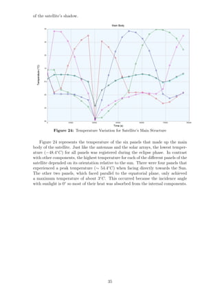
24 Temperature Variation for Satellite’s Main Structure . . . . . . . . . 35
25 Temperature Variation for Satellite’s Batteries . . . . . . . . . . . . . 36
26 Temperature Variation for Satellites Transponders . . . . . . . . . . . 37
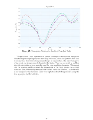
27 Temperature Variation for Satellite’s Propellant Tanks . . . . . . . . 38
28 ADCS Summary . . . . . . . . . . . . . . . . . . . . . . . . . . . . . 39
29 Trade Study between Attitude Determination Systems . . . . . . . . 39
30 Jena-Optronik Astro APS . . . . . . . . . . . . . . . . . . . . . . . . 40
31 Honeywell HR12s Reaction Wheel . . . . . . . . . . . . . . . . . . . . 41
32 ASTRIX 1090 . . . . . . . . . . . . . . . . . . . . . . . . . . . . . . . 41
33 Angle Perturbation due to Solar Torque . . . . . . . . . . . . . . . . 42
34 Wheel Properties . . . . . . . . . . . . . . . . . . . . . . . . . . . . . 43
35 System Interfaces [23] . . . . . . . . . . . . . . . . . . . . . . . . . . . 45
36 TT&C Requirements . . . . . . . . . . . . . . . . . . . . . . . . . . . 46
37 TT&C Block Diagram [23] . . . . . . . . . . . . . . . . . . . . . . . . 47
38 TT&C Parameters . . . . . . . . . . . . . . . . . . . . . . . . . . . . 47
39 TT&C Sizing . . . . . . . . . . . . . . . . . . . . . . . . . . . . . . . 48
40 Propulsion System . . . . . . . . . . . . . . . . . . . . . . . . . . . . 50
41 Apogee Kick Motor (AKM) . . . . . . . . . . . . . . . . . . . . . . . 50
42 Apogee Kick Motor Specs[2] . . . . . . . . . . . . . . . . . . . . . . . 51
43 RCS Thrusters . . . . . . . . . . . . . . . . . . . . . . . . . . . . . . 51
44 RCS Thruster Specs[3] . . . . . . . . . . . . . . . . . . . . . . . . . . 52
45 Propellant Manifold Block Diagram . . . . . . . . . . . . . . . . . . . 53
46 Propulsion Subsystem Weight and Power . . . . . . . . . . . . . . . . 54
47 Sum of all Subsystem Power Requirements . . . . . . . . . . . . . . . 55
4](https://image.slidesharecdn.com/ae5d3960-8a40-403b-bfee-af3b3be2e95a-150519205305-lva1-app6891/85/Capstone-Final-Report-4-320.jpg)
![48 Candidate Solar Cell Properties[23] . . . . . . . . . . . . . . . . . . . 56
49 Triple Junction GaAs Cell [26] . . . . . . . . . . . . . . . . . . . . . . 57
50 Solar Array Exploded View . . . . . . . . . . . . . . . . . . . . . . . 57
51 Calculation of Solar Array . . . . . . . . . . . . . . . . . . . . . . . . 57
52 Single DOF Solar Gimbal Motor [27] . . . . . . . . . . . . . . . . . . 58
53 PCDU [28] . . . . . . . . . . . . . . . . . . . . . . . . . . . . . . . . . 59
54 Depth of Discharge vs. Cycle [23] . . . . . . . . . . . . . . . . . . . . 60
55 Trade Study of Battery Characteristics . . . . . . . . . . . . . . . . . 60
56 Lithium Cobalt Oxide Battery Unit [18] . . . . . . . . . . . . . . . . 60
57 Cost of Solar Cell Technologies [23] . . . . . . . . . . . . . . . . . . . 61
58 Cost Calculation of Carbon Fiber Cloth [15] . . . . . . . . . . . . . . 61
59 Cost of Various Types of Batteries . . . . . . . . . . . . . . . . . . . 61
60 Battery Capacity . . . . . . . . . . . . . . . . . . . . . . . . . . . . . 61
61 Failure Graphs [8] . . . . . . . . . . . . . . . . . . . . . . . . . . . . . 62
62 Probability . . . . . . . . . . . . . . . . . . . . . . . . . . . . . . . . 62
63 Impact . . . . . . . . . . . . . . . . . . . . . . . . . . . . . . . . . . . 63
64 Impact . . . . . . . . . . . . . . . . . . . . . . . . . . . . . . . . . . . 63
65 Impact . . . . . . . . . . . . . . . . . . . . . . . . . . . . . . . . . . . 63
66 USCMB Non-Recurring . . . . . . . . . . . . . . . . . . . . . . . . . 64
67 USCMB Recurring . . . . . . . . . . . . . . . . . . . . . . . . . . . . 65
68 Application of USCMB . . . . . . . . . . . . . . . . . . . . . . . . . . 65
69 Side Exploded View . . . . . . . . . . . . . . . . . . . . . . . . . . . 66
70 Isometric Packed Payload . . . . . . . . . . . . . . . . . . . . . . . . 66
71 Side Packed Payload . . . . . . . . . . . . . . . . . . . . . . . . . . . 67
72 Space Side Assembly . . . . . . . . . . . . . . . . . . . . . . . . . . . 67
73 Communications Compartment . . . . . . . . . . . . . . . . . . . . . 68
74 Power Compartment . . . . . . . . . . . . . . . . . . . . . . . . . . . 68
75 Packed Upper Compartment . . . . . . . . . . . . . . . . . . . . . . . 69
76 Emergency and Launch Antenna . . . . . . . . . . . . . . . . . . . . 69
77 Battery Assembly . . . . . . . . . . . . . . . . . . . . . . . . . . . . . 70
78 Antenna Assembly . . . . . . . . . . . . . . . . . . . . . . . . . . . . 70
79 Computer . . . . . . . . . . . . . . . . . . . . . . . . . . . . . . . . . 71
80 Propulsion Compartment . . . . . . . . . . . . . . . . . . . . . . . . . 71
81 Transmitter & Receiver Antennae . . . . . . . . . . . . . . . . . . . . 72
82 Thrust and Interlock ESPA Manifold . . . . . . . . . . . . . . . . . . 72
83 Gyroscope . . . . . . . . . . . . . . . . . . . . . . . . . . . . . . . . . 73
84 Input/Output Multiplexer . . . . . . . . . . . . . . . . . . . . . . . . 73
85 Power Condition and Distribution Unit . . . . . . . . . . . . . . . . . 73
86 RCS Thruster . . . . . . . . . . . . . . . . . . . . . . . . . . . . . . . 74
87 Reaction Wheels . . . . . . . . . . . . . . . . . . . . . . . . . . . . . 74
88 Star Tracker . . . . . . . . . . . . . . . . . . . . . . . . . . . . . . . . 75
89 TT&C Antenna . . . . . . . . . . . . . . . . . . . . . . . . . . . . . . 75
90 Emergency Antenna . . . . . . . . . . . . . . . . . . . . . . . . . . . 76
91 Battery Array . . . . . . . . . . . . . . . . . . . . . . . . . . . . . . . 76
92 Apogee Kick Motor . . . . . . . . . . . . . . . . . . . . . . . . . . . . 77
93 Solar Array Gimbal . . . . . . . . . . . . . . . . . . . . . . . . . . . . 77
94 Transponder . . . . . . . . . . . . . . . . . . . . . . . . . . . . . . . . 78
95 Travelling Wave Tube Amplifier Array . . . . . . . . . . . . . . . . . 78
5](https://image.slidesharecdn.com/ae5d3960-8a40-403b-bfee-af3b3be2e95a-150519205305-lva1-app6891/85/Capstone-Final-Report-5-320.jpg)


![will be used. This launch meets every criteria necessary to place the satellite into
the desired orbit. The launch will take place from Cape Canaveral Florida with the
final characteristics outlined in fig. 7.
Figure 7: Launch Characteristics
5 Payload Design
5.1 Gain
Gain is the measure of directivity of an antenna. Gain is proportional to effective area
given by eq. (1) and eq. (2). For large antennas, the effective area is approximately
equal to the real area of the antenna.
G =
4 ∗ π ∗ Aeff
λ2
(1)
G = η ∗
π ∗ D
λ
2
(2)
Standard antenna efficiency (η) is usually between 55% to 70% and the standard
ground satellite antenna diameter is 0.5334 m but can range in size depending on the
need [5]. Typical LNB noise of satellite antenna is 1 dB, and as the EIRP increases,
the area of the antenna decreases [11]. It is important to know that EIRP helps
shape the coverage area when designing the antenna. At a bandwidth of 6 GHz,
the gain of a 10 m antenna will approximately equal 53.3 dB [20]. Also, for the
communication satellite to be most efficient, it is best to have an EIRP no less than
40 dBW.
5.2 Beam Trade Study
According to Tech-FAQ [9], a spot beam is a signal that is directed towards a specific
area on the surface. The advantage of using spot beams is that is allows a satellite
to target a specific area, which averts data interception and minimizes the power
utilized. Another advantage of spot beams is the capability to reuse a frequency
for different locations without interference at the receiver. This allows for more
channels to be carried on the same frequency which is then operated in several areas.
However, using spot beams to cover too many areas such as the entire continental
United States is not recommended because it take up too much power and may cause
data interference because the beams are grouped closely.
On the other hand, wide beams cover large geographical areas and a wide beam
over the continental United States is also known as CONUS [12]. An advantage of
wide beam is that it is more omni-directional than spot beams. This means that
19](https://image.slidesharecdn.com/ae5d3960-8a40-403b-bfee-af3b3be2e95a-150519205305-lva1-app6891/85/Capstone-Final-Report-19-320.jpg)
![Figure 8: Spot Beam vs. Broad Beam[12]
an antenna does not need to be pointed accurately in order to create a connection.
CONUS is also much simpler and more reliable than spot beams.
Cygnus Satellite LLC. will use CONUS for its communication satellite, which
means that it is necessary to choose between installing parabolic reflector dish and
shaped reflector antenna.
5.3 Antenna Trade Study
In order to use a parabolic reflector dish for CONUS it would be essential to adjust
the pointing and operating point of the reflector so that the gain at the edges of the
coverage area is within the requirements [23]. However, this means that gain over
most of the coverage will be greater than the minimum requirement, which requires a
lot of power. Another disadvantage of utilizing a parabolic reflector dish for a broad
beam is that covers areas that are not in the continental United States. Non-essential
coverage areas include oceans, Canada, or Mexico.
The above mentioned disadvantages of utilizing a parabolic reflector dish for
broad beam can be fixed creating a shaped reflector antenna specific to cover CONUS.
Shaped reflector antenna produces a broad beam that conforms more closely to
the coverage area by limiting transmitted power, which is why a a shaped reflector
antenna is better. Examples of the parabolic reflector dish and shaped reflector
antenna are observed in fig. 9 and fig. 10, respectively.
20](https://image.slidesharecdn.com/ae5d3960-8a40-403b-bfee-af3b3be2e95a-150519205305-lva1-app6891/85/Capstone-Final-Report-20-320.jpg)

![5.4 Frequency Band
Although Ku-band systems are more abundantly used today, Ka-band systems are
an up and coming competitors. With both systems offering certain advantages, it is
beneficial to compare the two bands in order to ensure an optimal design. The figure
below [7] shows the ranges of both the Ku and the Ka-band along with the effects
of rain on signal dissipation. The table and figures below show a more in-depth
Figure 11: Range of Frequency Bands
comparison of Ku-band systems and Ka-band systems. After being introduced in
the 1980s, the coverage of Ku-band systems has significantly increased over the past
30 years [16]. However, this has resulted in less carrier frequencies being available for
new systems. The new Ka-band systems are able to offer higher downlink data rates
but fall short in regions with high rain weather [1]. As can be seen in the figures
below, for harsh regions, cost for Ka-band systems drive-up exponentially which can
cause problems when providing service to areas in CONUS where this type of weather
is common. Even in temperate regions the cost drives up exponentially as higher
availability is demanded. In conclusion, Ku-band systems are superior due to being
a well-established system and due to its higher overall reliability.
Criteria Band Ku Ka
Cost per BPS (bits
per second)
Offer competitive cost per BPS
compared to same spot beam size
Ka-band systems
Provide same cost per BPS for
smaller spot beam systems. Link
performance deteriorates as spot
beam coverage increases
Coverage Provide same coverage as Ku-
band large spot beams. EIRP is
the same for both bands, but Ku-
band systems have high signal
gain. Frequency reuse increases
coverage
Ka-band small spot beams pro-
vide significantly less coverage
than Ku-band systems. Lower
signal gain for similar size anten-
nas. Lack of frequency reuse lim-
its coverage
In Case of System
Failure
The existence of a large-number
of Ku-band satellites allows for
reallocation of service to other
satellites
The scarcity of Ka-band satel-
lites denies Ka-band systems the
same benefits as the Ku-band
systems
Weather Less energy dissipation due to
rain. Less overall cost vs avail-
ability in most regions (see fig-
ures below)
High signal loss due to rain. Cost
are escalated as higher availabil-
ity is demanded (see figures be-
low)
Table 1: Frequency Band Trade Study
22](https://image.slidesharecdn.com/ae5d3960-8a40-403b-bfee-af3b3be2e95a-150519205305-lva1-app6891/85/Capstone-Final-Report-22-320.jpg)

![to buy. In addition, the receiving and transmitting dishes on the satellite were sized
to be 1.5 meters in diameter each, with a gateway dish size of 10 meters in diameter.
All dishes were sized to allow for a greater link margin, which helped account for any
attenuations due to signal losses or inclement weather conditions. Beyond bandwidth
considerations, the home dish size was influenced by the volatile nature of weather-
induced signal attenuations, which if made too small would prevent clear broadcast
at the specified data rate. The link budget analysis can be seen in fig. 13
Figure 13: Link Budget
In order to conduct the analysis, assumptions also had to be made about the losses
involved in the system, which were assumed to be worst case scenario values [23].
Incorporated losses included those due to the antenna, circular depolarization losses,
atmospheric losses, pointing losses, and freespace losses from a geosynchronous orbit.
In addition, each antenna was assumed to operate at an efficiency of 70% for the
satellite antennas and the worst case efficiency for the uplink ground antenna and the
home receiver of 55%. For further investigation into the equations and assumptions
made, refer to the source code in the appendix section.
These results from the analysis are very reasonable when compared to other
communication satellites. From this analysis we can see that we have a link margin
of 14.1038 dB which provides an additional tolerance for any attenuations between
the transmitter and the receiver. This high link margin allows for indirect signals
to be able to bounce off of any other surfaces and still be received by the ground
dish. To some companies this link margin may be considered to be too large but we
want to ensure that the link is made between the satellite and the user under any
circumstance.
24](https://image.slidesharecdn.com/ae5d3960-8a40-403b-bfee-af3b3be2e95a-150519205305-lva1-app6891/85/Capstone-Final-Report-24-320.jpg)
![5.6 Hardware and Bandwidth
In satellites, back-end amplifiers are used to increase the strength of processed signals.
Signals received through the antenna are filtered from the array, and passed through
the transponder with the appropriate bandwidth allocation. The transponder multi-
plexes the signal frequency by shifting (translating) its center frequency down to the
frequency necessary for downlink, then passes the signal through a power amplifier,
which increases the signal strength. Finally, the signal is passed to the downlink
antenna, where it is transmitted to the end user. Traditionally used in satellites,
vacuum tubes amplify signals into the Ultra-High-Frequency (UHF) or even the Mi-
crowave frequency range via a generally analogous principle. A series of resonators
are resonated with the signal of interest, and the energy from an electron beam pass-
ing through the resonators is transferred to the signal, increasing its strength. In
solid state amplifiers, this same effect is accomplished through careful manipulation
of electron flow via control of the semiconductor pathways within the material itself.
There are a number of drawbacks to the use of vacuum tubes in satellites, the most
problematic of which being an inherently low durability due to the fragile nature of
their construction. Additionally, amplified signals suffer from non-linear distortions
outside of a very narrow bandwidth, severely limiting their transmission capability
and therefore increasing the number of amplifiers/transponder pairs needed. Solid-
state devices in general are smaller, more reliable, and cheaper than their tubular
ancestors, seemingly making them the ideal candidate for future Cygnus satellites.
It is worth noting that a number of experts on the subject still to this day
prefer vacuum tube amplifiers due to a measurably higher quality thermionic energy
conversion than can be achieved in solid-state amplifiers. This slight increase in
efficiency however is offset by the non-linear wide-band distortions introduced into
signals amplified by vacuum tubes. In order to make the decision between Solid State
Power Amplifiers (SSPA) and Travelling Wave Tube Amplifiers (TWTA), a number
of traits had to be considered (Figure 14). Despite the increased mass, TWTAs
exhibit a significant increase in efficiency over SSPAs in applications which require a
high data rate and satellite altitude. TWTAs are however less durable, bulkier, and
introduce more signal distortion at the ends of their bandwidth range than SSPAs.
Despite all of these drawbacks, the extremely limited power available ultimately plays
the largest role, resulting in the decision to use TWTAs in our satellite. Increased
power consumption, as will later be shown, has a cascading effect on mass, cost, and
risk.
Figure 14: Amplifier Trade Study[23]
In the Ku band, bandwidth allocations are typically 500 MHz wide. In the
Cygnus satellite being designed, a circular polarization scheme was chosen in order to
increase the amount of stations being broadcast to the end user by utilizing the both
the vertical and horizontal electromagnetic wave components. Research into power
system aboard the Horizons-1 satellite yielded power and bandwidth information on
its TWTA transponders. We have therefore assumed a 36 MHz bandwidth, and
108 Watt power consumption per transponder [21]. Transponder mass values were
25](https://image.slidesharecdn.com/ae5d3960-8a40-403b-bfee-af3b3be2e95a-150519205305-lva1-app6891/85/Capstone-Final-Report-25-320.jpg)
![attained from the product page of the L-3 transponders which were chosen for this
system (fig. 15).
Figure 15: TWTA Amplifier [10]
In accordance with SMAD values, an inter-channel gap bandwidth and station-
keeping bandwidth of 4 MHz each was assumed. fig. 16 displays the architecture
of signal polarization. A Matlab Script incorporating all these values yielded the
following results:
• Total number of channels = 23
• Total number of stations per channel = 24
• Total number of digital TV stations transmittable = 552
• Total number of transponders including spares = 30
• Total mass of transponders and amplifiers including spares and power convert-
ers = 153.9 [kg]
• Total power of transponders and amplifiers including = 2484.0 [W]
Figure 16: Polarization Architecture
26](https://image.slidesharecdn.com/ae5d3960-8a40-403b-bfee-af3b3be2e95a-150519205305-lva1-app6891/85/Capstone-Final-Report-26-320.jpg)
![6 Subsystems
6.1 Structure
The space environment is very demanding on materials. The combination of huge
swings in temperature from thermal cycling, exposure to large amounts of radiation,
oxidation, outgassing, and large forces during launch make for a difficult materials
problem. In addition, the structure needs to act as a skeleton for the assembly of
the subsystems so it must be easily integrated with all other systems. For the cost
of the structure to remain low, the structure needed to be made out of components
that are compatible with current manufacturing processes.
In order to combat the wide range in thermal cycling it was important to use a
material with a very small thermal expansion. The temperature the spacecraft would
face can range from -160 C to +180 C which demanded the material to be able to
withstand extremely hot and cold temperatures. In addition, electromagnetic and
particle radiation from the radiation belts, solar emissions and other cosmic radiation
had to be taken into effect. However, these effects were considered negligible due
to the small impact they had on the structure. In addition, the material needed
to be strong to overcome the accelerations, acoustic effects and thermal effects from
launch. The loads at launch proved to be the largest strain on the structure during its
mission lifetime. While the material needed to be strong, almost more importantly,
it also needed to be very lightweight to reduce the costs associated with launch.
There were several possible materials that met these requirements. Currently,
the majority of spacecraft structures are made out of aluminum alloys. Some alloys
meet most of the requirements as outlined above. They have a high stiffness, mod-
erate thermal expansion, moderate cost and are readily available in many forms. In
addition, their stiffness to density ratio is very high which results in high strength
for relatively low mass. Titanium also presented another good option because it
surpasses the properties of aluminum in most areas. Titanium is extremely strong,
has an even higher stiffness to density ratio than aluminum and also has a moderate
thermal expansion coefficient. However, titanium is very expensive, hard to machine
and not as readily available as aluminum [6].
In addition to aluminum and titanium there were several other exotic metals
that could be used, the first option being beryllium. With a stiffness to density
ratio much higher than titanium it could be a very light and useful material for the
structure. However, beryllium is very brittle and does not maintain its properties
well at low temperatures. In addition, the material is very expensive to purchase and
extremely expensive to machine due to the toxicity of the dust created during the
manufacturing process. Another option was magnesium. This metal has a similar
stiffness to density ratio as aluminum but operates poorly at low temperatures.
The final and best option were composite materials. With a stiffness to density
ratio far exceeding any metal, composite materials are significantly stronger and
lighter than any other options. In addition, composite materials have a negative
thermal expansion coefficient making it suitable to operate in the thermal extremes
of space. However, rapid temperature changes can cause strains in the material
meaning there would have to be insulated with another material [13].
There are many different types of composite materials but the best for this ap-
plication was carbon fiber. Carbon fiber has high strength and stiffness, fatigue
insensitive, very light and relatively low cost [17]. Currently, there are many carbon
fiber manufactures that can provide the structural members that would be necessary
27](https://image.slidesharecdn.com/ae5d3960-8a40-403b-bfee-af3b3be2e95a-150519205305-lva1-app6891/85/Capstone-Final-Report-27-320.jpg)
![for the main structure of the satellite. It was therefore decided that the structure
would be made out of carbon fiber reinforced polymer square tubes. The structure
consisted of 1 inch square tubing with a wall thickness of 0.022 inches.
The carbon fiber structure was encapsulated in 5 mm thick aluminum 6061 panels
that served as additional structural support and a surface for attachments. At the
bottom of the satellite a thrust cone was used to house the main apogee kick thruster.
This cone consisted of the same carbon fiber as the main structure with a heat-
resistant lining to help isolate internal components from the massive amounts of
heat given off by the main apogee burn. The entire structure, including the antenna
bus structure, the back of the antennas and the back of the solar panels, were then
covered in multi-layer insulation (MLI) for thermal insulation. MLI reduces heat
losses due to thermal radiation by increasing thermal resistance and reducing the
rate of heat transfer.
A structural analysis of the structure was conducted using the SolidWorks sim-
ulation tools. Using the Falcon 9 user guide, a design load factor of 6 was applied
to the center of gravity of the structure [19]. A load factor of 6 was then applied in
the axial direction to account for the worst case scenario the structure will face upon
launch. The results of the stress analysis and the displacement can be seen in fig. 17
and fig. 18 respectively.
Figure 17: Static Stress Analysis
28](https://image.slidesharecdn.com/ae5d3960-8a40-403b-bfee-af3b3be2e95a-150519205305-lva1-app6891/85/Capstone-Final-Report-28-320.jpg)
![Figure 18: Deformation
From these results the greatest displacement of 0.6244mm was seen to occur at
the center apex of the structure. This displacement was an acceptable result is it was
insufficient of causing any problems for the integrity of the structure. In addition,
the stress distribution would not have a significant impact on the structure as the
maximum stress on the structure was found to be 8.502 ∗ 106 N
m2 . This resulted
in a factor of safety margin of 24. This structural analysis demonstrated that the
structure was well within safety margins and would easily withstand any forces it
encountered upon launch.
The satellite was designed to connect to the Falcon 9 fairing using the EELV
secondary payload adapter (ESPA). This adapter not only mated the Cygnus satellite
to the fairing but allowed for the addition of up to six small satellites with a maximum
mass of 180 kg to be attached to the adapter [14]. By including this capability, it
allowed for launch costs to be shared with other consumers in order to minimize cost.
The ESPA adapter has become a standard in the industry and is a notably reliable
system. The antenna bus structure was then constructed using carbon fiber, and
attached to its motorized antenna deployment mechanism (ATM) made by Airbus
Defense and Space. This technology is a proven and reliable deployment system. It is
critical that the ATM does not fail due to the mission critical role that the antennas
play.
In fig. 19 the general configuration of the subsystems inside the satellite are
visible. All of power components for the solar panels as well as the housing for the
apogee kick motor were fixed to the the bottom platform. Attached to the second
platform were the propellant tanks for all of the RCS thrusters and the main apogee
kick motor. The top section included all of the other components associated with
29](https://image.slidesharecdn.com/ae5d3960-8a40-403b-bfee-af3b3be2e95a-150519205305-lva1-app6891/85/Capstone-Final-Report-29-320.jpg)

![largest strain energy at the launch vehicle interface site [23]. One difficulty encoun-
tered in performing frequency analysis is due to the fact that area moment of inertia
varies throughout the entire structure. Therefore, it was assumed that bending stiff-
ness was based upon the launch vehicle interface. One major constraint that dictated
the fundamental frequency was the length of the payload, due to the cubed length
term in eq. (4). The light carbon fiber frame and the large modulus of elasticity did
however act to mitigate the effects of this mathematical result.
The ESPA had an outer diameter and inner diameter of .9609m and .9394m
respectively, and a modulus of elasticity of 1.75 ∗ 101
1. The length of the payload is
3m and the mass of the structure is assumed to be 128.94kg. At a payload length
of 3 meters and 128.94 kilogram, the area moment of inertia was estimated to be
.0036216m4
, resulting in a final fundamental frequency of 117.618Hz. This value
is a reasonable preliminary estimation for the fundamental frequency as it is larger
than the fundamental frequency of the launch vehicle. However, further frequency
analysis should be done using current software in order to better simulate the launch
environment and structural properties. The final mass estimates can be seen in
fig. 20. The fastener estimate was based on 15% of the dry mass of the structure
[23].
Figure 20: Structure Mass Summary
31](https://image.slidesharecdn.com/ae5d3960-8a40-403b-bfee-af3b3be2e95a-150519205305-lva1-app6891/85/Capstone-Final-Report-31-320.jpg)
![6.2 Thermal
Satellites in orbit are required to operate in an environment with constant and ex-
treme temperature changes. The spacecraft absorbs heat through sunlight, albedo,
and planet emitted radiation. It also produces heat internally through power dissi-
pation, mainly from electrical components. The thermal subsystem is responsible for
setting and maintaining the temperature range for the satellite and its components.
This thermal control is important because all of the components require a specific
operating temperature range. These operating temperatures are maintained by ac-
tive systems such as radiators and heaters, and passively by coating components with
specific emissivity and absorptivity properties [4, 23].
The thermal analysis was done using Thermica in order to analyze temperature
changes undergone by components throughout the satellite. This information was
then used to design thermal maintenance systems This analysis included a rough
model of the overall design of the spacecraft. The model included a main struc-
ture, antennas, solar arrays, radiators, electronic components, batteries, and the
propellant tanks. Although only two electronic components and three batteries were
created, their properties and parameters were modeled to represent the overall num-
ber of each component. Each of the satellites main components were modeled to its
unique physical and thermal parameters. The physical properties included materi-
als, thickness, dimensions, density, and coatings. The thermal properties included
specific heat, conductivity, emissivity, and absorptivity. The electronic components
such as transponders, radiators, and batteries also included their own power dissi-
pations which represented the heat they radiated inside the satellite. After running
the simulation, preliminary results were obtained which provided an estimate of the
satellites maximum and minimum temperatures as well as the temperature gradients
for the components. These results needed to be compared to the operating tempera-
tures of the components, and the design was modified in cases where the temperature
reached temperatures below or above the operating range.
Figure 21: Temperature Range
Figure 21 represents the preliminary results for maximum and the minimum tem-
peratures the components experienced during one orbit. The orbit used in the sim-
ulation was a geostationary orbit during the spring equinox. This orbit was unique
since during this time the satellite had to travel through Earth’s shadow. This eclipse
had a duration of 72 minutes and the satellite experienced its lowest overall temper-
ature. All the main components fit into two distinct outcomes depending on their
temperature variations. The antennas, solar arrays, and the main body experienced
a wide range of temperatures both positive and negative. The batteries, transpon-
ders, and propellant tanks had a more compact temperature difference. The main
32](https://image.slidesharecdn.com/ae5d3960-8a40-403b-bfee-af3b3be2e95a-150519205305-lva1-app6891/85/Capstone-Final-Report-32-320.jpg)


![6.3 Attitude Control
Due to the presence of disturbances while the satellite was in operation, the orienta-
tion, or attitude, of the satellite was perturbed from a desired or optimal location.
This was where an attitude control system was implemented in order to ensure that
the satellite was oriented properly. The attitude was adjusted by using utilizing a
combination of star trackers, gyroscopes, momentum wheels, reaction wheels, and re-
action control thrusters. In addition, the satellite was capable of being spin-stabilized
or three-axis stabilized each of which required a different combination of the afore-
mentioned hardware.
Figure 28: ADCS Summary
For this mission, Cygnus LLC decided to design a satellite that was three-axis
stabilized using a combination star trackers, reaction wheels, and thrusters.
6.3.1 Star Tracker
A star tracker utilizes a camera to measure the position of star(s) and is able provide
three-axis stabilization using the acquired data. The figure below [22] shows a trade
study that was performed in order to choose between Star Tracker, Earth Sensors,
and Sun Sensors. For this mission, the star tracker utilized was provided by Jena-
Optronik.
Figure 29: Trade Study between Attitude Determination Systems
39](https://image.slidesharecdn.com/ae5d3960-8a40-403b-bfee-af3b3be2e95a-150519205305-lva1-app6891/85/Capstone-Final-Report-39-320.jpg)
![Figure 30: Jena-Optronik Astro APS
6.3.2 Reaction Wheels
Reaction wheels were utilized in order to change the orientation of the satellite by
spinning the wheels along a specified axis. Reaction wheels are also capable of
being utilized as momentum wheels by spinning them at a constant angular speed
which builds up angular momentum and greatly reduces any disturbance torques
that operating on an axis parallel to the rotational axis of the reaction wheel. For
this mission, four reaction wheels were utilized to provide accurate control. The
orientation of the wheels was determined by analyzing the results of a study done
by University Putra Malaysia [29]. In the study, three and four reaction wheel
orientations were analyzed and the chosen orientation produced the lowest amount
of torque. The reaction wheels chosen for this mission were Honeywells HR-12. Their
design and orientation is shown below. These wheels have a maximum momentum
of 50 N-m-s. The saturation rate was conservatively approximated to be 5 days per
momentum unloading. This gave a propellant mass of ∼ 47kg that will be utilized
throughout the lifetime of the satellite in order to unload momentum. This was
calculated using the saturation rate of the reaction wheels, which is once every 5
days, and the duration the thrusters will be fired, which is 1 second [24].
40](https://image.slidesharecdn.com/ae5d3960-8a40-403b-bfee-af3b3be2e95a-150519205305-lva1-app6891/85/Capstone-Final-Report-40-320.jpg)


![6.4 Telemetry, Tracking, and Command
6.4.1 Introduction
The telemetry, tracking, and command (TT&C) subsystem is a vital part of the
satellite system. Nearly all onboard subsystems interface with the TT&C subsystem
in some way. Information regarding satellite health, tracking, and performance is
communicated from the spacecraft to the ground facilities, where they are interpreted
and analyzed to ensure that the mission is going as planned. Command functions are
generated based on telemetry and ranging readings, and are uplinked to the satellite
where these commands are executed. There are five main subsystem functions of
TT&C [23]:
• Carrier tracking (lock onto the ground station signal)
• Command reception and detection (receive the uplink signal and process it)
• Telemetry modulation and transmission (accept data from spacecraft systems,
process them, and transmit them)
• Ranging (receive, process, and transmit ranging signals to determine the satel-
lites position)
• Subsystem operations (process subsystem data, maintain its own health and
status, point the antennas, detect and recover faults)
6.4.2 Assumptions
For both the uplink and downlink analyses during normal operations, it was assumed
that the antennas are pointed perfectly towards each other (boresight pointing).
During the launch phase and subsequent transfer, near-perfect pointing for the anti-
Earth-facing antenna was assumed for the sake of simplicity. It was also assumed
that no more than one TT&C transponder/antenna will fail. All dimensioning, mass,
and power assumptions were made from handbook references. Cygnus assumed single
ground station control during nominal satellite operations, and a capable third-party
tracking network during launch operations.
6.4.3 System Interfacing
The TT&C subsystem interfaces with every subsystem on the spacecraft with the
exception of the propulsion subsystem, and must reliably pass information back and
forth. A table displaying this interfacing is displayed below in fig. 35:
44](https://image.slidesharecdn.com/ae5d3960-8a40-403b-bfee-af3b3be2e95a-150519205305-lva1-app6891/85/Capstone-Final-Report-44-320.jpg)
![Figure 35: System Interfaces [23]
45](https://image.slidesharecdn.com/ae5d3960-8a40-403b-bfee-af3b3be2e95a-150519205305-lva1-app6891/85/Capstone-Final-Report-45-320.jpg)
![Figure 37: TT&C Block Diagram [23]
Two-layer redundancy ensured mission continuation in the event of a single
TT&C transponder failure. Use of a diplexer allowed the use of one antenna for
both transmitting and receiving. While not shown on the block diagram, a low-gain
hemispherical omni-directional antenna mounted on the anti-Earth-facing side of the
satellite was used during the launch phase of the mission, and during emergency op-
erations. This provided a final third layer of redundancy for the Cygnus TT&C
subsystem. The modulation method used by the TT&C subsystem was BPSK/PM
modulation, where the carrier and data were transmitted at frequencies separated by
the subcarrier frequency. Data rates were taken from the suggested values in SMAD
(Table 11-19) [23]. The parameters for the Cygnus TT&C system are as follows:
Figure 38: TT&C Parameters
Sizing for the TT&C subsystem was also performed via the SMAD handbook.
Table 11-26 [23] lists typical parameters for TT&C subsystems; Cygnus used a Ku-
band communications subsystem for TT&C, and therefore used these parameters:
47](https://image.slidesharecdn.com/ae5d3960-8a40-403b-bfee-af3b3be2e95a-150519205305-lva1-app6891/85/Capstone-Final-Report-47-320.jpg)


![Figure 42: Apogee Kick Motor Specs[2]
6.5.4 Reaction Control System (RCS) Thrusters
In all satellites, some form of a reaction control system is necessary for attitude
control and station-keeping. In the case of the Cygnus satellite, this role will be
fulfilled by a system of RCS thrusters and reaction wheels. Figure 43 shows the
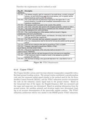
requirements Cygnus Satellite considered before choosing its RCS thrusters. Cygnus
Satellite LLC chose the MR-111C 4N (1.0-lbf) Rocket Engine Assembly which is
a monopropellant system that utilizes hydrazine, however, since MMH is a more
volatile type of hydrazine, it was decided to use MMH instead. This will reduce the
number of propellant tanks, which greatly reduced the mass of the satellite.
(a) RCS Info (b) RCS Thruster Assembly
Figure 43: RCS Thrusters
51](https://image.slidesharecdn.com/ae5d3960-8a40-403b-bfee-af3b3be2e95a-150519205305-lva1-app6891/85/Capstone-Final-Report-51-320.jpg)
![Figure 44: RCS Thruster Specs[3]
6.5.5 Propellant Manifold
The last part of the propulsion subsystem was the propellant manifold, which encom-
passed all the hardware required to regulate propellant flow between the propellant
tanks and the thrusters. The propellant manifold consisted of thruster valves, lines
and fittings, isolation valves, pyro valves, filters, fill and drain valves, pressure trans-
ducers, and flow control orifices.
The materials most commonly used to construct the lines and fittings in satellites
are titanium and stainless steel. Titanium is lighter and more compatible with
oxidizers, however stainless steel is less expensive and easier to handle [23]. It was
decided to utilize titanium for its lines and fittings in an effort to keep the satellite
as efficient as possible.
The two essential valve types utilized in the propellant manifold included isolation
valves and pyro valves. Isolation valves have the capability to permanently open
or close without a continuous power supply. This property allows isolation valves
to serve multiple functions, one of which includes isolating a group of thrusters in
the event of system failure. Isolation valves may also control spacecraft mass by
containing a specific tank in multi-tank system. On the other hand, pyro valves are
one-time use valves, which means that these valves are either normally opened or
closed. Pyro valves may serve the same function as isolation valves, however they
can only be operated once. The advantage of utilizing pyro valves include lower leak
rates, decreased pressure drops, and smaller mass. Pyro valves may be used to isolate
components in order to satisfy safety and reliability issues, and isolate components
after use. A system of both types of valves must be utilized in order to create the
most efficient propellant manifold.
52](https://image.slidesharecdn.com/ae5d3960-8a40-403b-bfee-af3b3be2e95a-150519205305-lva1-app6891/85/Capstone-Final-Report-52-320.jpg)
![It is standard practice to install filters downstream of tanks and fill/drain valves,
because this is where the most particulates can be captured. The size of the fil-
ter depends on the amount propellant required to pass through the filter, size of
particulate filtration, and allowable steady state pressure drop [23].
Fill and drain valves were next installed on a manifold, and had to remain ac-
cessible at all times to allow for emergency offloading. The addition of pressure
transducers allowed for the pressure monitoring required for propellant loading and
pressurization. Pressures transducers were also utilized to evaluate the performance
of the system. Finally, flow control orifices were installed to equalize pressure drops
between the feed lines between the oxidizer and fuel lines, which ensured a stable
oxidizer to fuel ratio. Flow control orifices were also used to minimize transient flow,
which can cause dangerous pressure spikes. Figure 45 illustrates the basic block di-
agram of the 4.5 kg propellant manifold that Cygnus Satellite LLC plans to install
in its new satellite.
Figure 45: Propellant Manifold Block Diagram
53](https://image.slidesharecdn.com/ae5d3960-8a40-403b-bfee-af3b3be2e95a-150519205305-lva1-app6891/85/Capstone-Final-Report-53-320.jpg)

![6.6 Power System
Figure 47: Sum of all Subsystem Power Requirements
Once all of a spacecrafts power requirements are accounted for, its power source
must be designed to meet those demands, which in this case will be a solar ar-
ray. While satellites that provide internet and telephone services have a fluctuating
demand for communication system power, this apply to direct broadcast television
satellites. While the content of the television programming is subject to change based
on the time of day, the power requirement of the Cygnus satellites communication
will remain constant 24 hours a day until the day it is de-orbited. Therefore, the
solar arrays must be sized to provide enough power in the daylight hours to both
supply the normal daylight power requirements, as well as charge the batteries which
provide the spacecraft with power during eclipses. The necessary power generated
by the solar array during daylight is given by eq. (12)
Psa =
PeTe
Xe
+ PdTd
Xd
Td
(12)
Pd = Pe +
Cbat[W − hr]
(Td[hr])
(13)
In this case, the power requirement during eclipse is simply the sum of all subsys-
tem power requirements (minus battery charging). The daylight power also includes
these standard operating values, as well as the power required to charge the battery
array (eq. (13)). Based on the wobble of Earth’s polar axis with respect to the plane
of the Ecliptic, the amount of time spent by Cygnus eclipsed in Earth’s shadow each
revolution changes throughout the year. It is at the height of these eclipse seasons
that the solar array needed to be sized, in order to ensure adequate power production
55](https://image.slidesharecdn.com/ae5d3960-8a40-403b-bfee-af3b3be2e95a-150519205305-lva1-app6891/85/Capstone-Final-Report-55-320.jpg)
![at this point of highest energy storage demand. Thus, an eclipse period of 72 minutes
was used.
In order to determine which type of solar cell to use, a trade study between the
properties of various materials was analyzed (fig. 48) As can be seen from fig. 48,
Figure 48: Candidate Solar Cell Properties[23]
there are a number of major differences between the cell types. Cost is always a
driving factor, though not of higher priority than product quality in the case of the
Cygnus satellite. This company policy meshes well with the recent advances in solar
cell manufacturing which have made Triple Junction GaAs cells an affordable, high-
quality option. Their high efficiency and impressive EOL properties also make them
a desirable candidate for the solar arrays on our satellite. Once the solar cell type
was chosen, its efficiency was used to calculate the maximum power output per area
with the Sun normal to the array (eq. (15)). This value was then multiplied by a
nominal inherent degradation value of 0.72, and the normal component of sunlight at
the worst-case Sun incidence angle of 23.7◦
, present during the summer and winter
solstice to find the Beginning Of Life (BOL) power output per area of the solar array
(eq. (15)).
Po = 0.30 ∗ 1369
W
m2
(14)
PBOL = PoId cos(θ) (15)
Next, the GaAs Triple Junction cell degradation rate of 0.5%/yr was used along
with a mission duration of 15 years in order to find lifetime cell degradation (eq. (16)).
End of life power per area was then calculated (eq. (17)), and used to calculate the
necessary solar array area to provide the Cygnus satellite with adequate power for
the entirety of its missions duration (eq. (18)).
Ld = (1 − D)L
(16)
PBOL = PBOLLd (17)
Asa =
Psa
PBOL
(18)
Using a preliminary total power value of 4.846 kW, a necessary solar array area
of 31.03m2
was calculated. A Triple Junction GaAs cell manufactured and marketed
by Azur Space was used as a model for this project (fig. 49). The surface features
visible are integrated power leads and bypass diodes, necessary to connect and elec-
trically isolate the cell in case of damage or structural shadowing. Bypass diodes
are necessary due to an increased resistance solar cells inherit when partially or fully
shadowed. Construction of the solar array began with an aluminum honeycomb sup-
port structure. Next, a layer of carbon fiber cloth was added to provide thermal and
impact insulation to the solar cells. A mounting structure was attached to the top of
56](https://image.slidesharecdn.com/ae5d3960-8a40-403b-bfee-af3b3be2e95a-150519205305-lva1-app6891/85/Capstone-Final-Report-56-320.jpg)
![this layer, in which all cells were installed. The anti-sun facing side was then covered
in a layer of MLI in order to help regulated thermal dumping. All layers are fixed
together via an aerospace adhesive. The exploded view of this design is visible in
fig. 50. The mass of a given solar array segment was tracked by adding the mass of
all of its components (fig. 51).
Figure 49: Triple Junction GaAs Cell [26]
Figure 50: Solar Array Exploded View
Figure 51: Calculation of Solar Array
57](https://image.slidesharecdn.com/ae5d3960-8a40-403b-bfee-af3b3be2e95a-150519205305-lva1-app6891/85/Capstone-Final-Report-57-320.jpg)
![In order to maximize power generation, a 1 Degree of Freedom (DoF) configu-
ration was chosen. In a 1-DOF system, the sun incidence angle decreases by 23.5◦
at the Winter and Summer solstices, an acceptable loss in avoiding the added struc-
tural complexity associated with a 2-DOF system. A low-power, high-torque gimbal
motor manufactured and distributed by MOOG [27] was therefore chosen to provide
solar array rotation (Figure 52). During the launch phase of the satellites life, the
solar array will be folded up and secured against the side of the satellite by explosive
bolts. Once the apogee burn is complete, the explosive bolts will detonate, and the
torsional springs fixed to the inter-segment hinges will provide torque which extends
the solar array fully. The next step in the power system sizing was the determination
of the Bus Voltage, an important step in the selection of a Power Conditioning and
Distribution Unit (PCDU). Power losses increase as resistance and current increases,
and as result of Ohms Law, power losses increases proportional to the square of
current (eq. (19)).
P = I2
R (19)
Figure 52: Single DOF Solar Gimbal Motor [27]
Therefore, minimizing power loss is a matter of increasing operating voltage (De-
sign of Geosynchronous Satellites). Power distributors which operate at higher volt-
ages are ideal, thus the Thales Group Power Conditioning and Distribution Unit
Medium Power Unit [28] was selected (Figure 53). This unit has the capability to
operate in both unregulated and regulated voltage modes. In an unregulated system,
individual loaded components require their own voltage regulation circuitry. Reg-
ulated systems eliminate this need for redundant circuitry at the price of slightly
reduced power efficiency (Agrawal). In order to decrease overall system complex-
ity, a regulated bus voltage of 50 Volts was decided upon despite the nominal drop
in efficiency. The Thales Group PCDU is ideal due to its high bus voltage, which
corresponds well with the maximum voltage produced by solar panels at the point
which the satellite reemerges from the eclipse. In order for these values to match, the
individual Gallium Arsenide half-cells (Figure 48) which have an EOL open-circuit
voltage 2.522 Volts each will be wired in 19-cell series to produce a voltage of 47.918
Volts. A total of 537 series will then be wired in parallel and connected to the
58](https://image.slidesharecdn.com/ae5d3960-8a40-403b-bfee-af3b3be2e95a-150519205305-lva1-app6891/85/Capstone-Final-Report-58-320.jpg)
![Figure 53: PCDU [28]
PCDU in order to encompass all cells. In order to ensure that power losses stay at
a minimum, components further away from the conditioning and distributing unit
will have power transferred to them via smaller gauge wires in order to ensure that
localized bus voltage never drops below too far below 50 V. Next came the design
of the battery array, which provides power to the spacecraft during eclipses. This
process began by finding the necessary battery capacity, which was a function of
worst case eclipse energy required, and EOL battery Depth of Discharge (eq. (20)).
CBat =
CbatTe
DOD ∗ ηb
= 2854.4 kW − hr = 571.49 A − hr (20)
A batterys Depth of Discharge (DOD) is defined as the total battery capacity avail-
able for discharge, and varies from battery to battery based on chemistry (Figure 54)
After multiple charge/discharge cycles, a batterys DOD drops, decreasing the effec-
tive energy available to the subsystems.
Other pros and cons associated with the various battery chemistries also had
to be considered, important factors included energy density, energy efficiency and
temperature range, a general trade study of which was analyzed (Figure 55). Since
required energy capacity is independent of battery chemistry, energy density of a
given battery will affect both the mass and proportions of the power subsystem. En-
ergy efficiency will affect the available battery capacity required, also affecting mass
and size of the battery array. Temperature range will affect the complexity of ther-
mal regulation systems, a smaller range corresponding to a more precise regulation
of battery temperature.
For a 15 year mission, the battery system will undergo 1350 charge/discharge cy-
cles due to the two annual 45 day eclipse seasons. Nickel-Cadmium batteries undergo
a significant degradation in depth of discharge over this many cycles, disqualifying
them from consideration in this mission. At the other end of the spectrum, Nickel
Hydrogen batteries undergo no DOD losses in a mission of this duration, making
them ideal. Lithium-ion batteries do suffer from DOD loss, but only nominally.
In considering all these factors, the decision was made to utilize a Lithium-ion
battery, with the only drawbacks being a slight DOD loss at EOL, and an increase in
complexity in the battery thermal regulation system. Searching for a viable candi-
date product yielded few results however, as it is apparently not common practice for
aerospace battery companies to publish their product specifications online. Eventu-
ally, a viable Lithium Cobalt Oxide battery was found, designed and manufactured
59](https://image.slidesharecdn.com/ae5d3960-8a40-403b-bfee-af3b3be2e95a-150519205305-lva1-app6891/85/Capstone-Final-Report-59-320.jpg)
![by the American company Eagle-Picher (Figure 56) [18]. In order to determine
the number of necessary batteries, the actual battery capacity was divided by the
published available battery capacity per unit (200 A-hr), and rounded up (eq. (21)).
Nbat =
CBat[Whr])
Vbus
Cactual
= 3 (21)
Figure 54: Depth of Discharge vs. Cycle [23]
Figure 55: Trade Study of Battery Characteristics
Figure 56: Lithium Cobalt Oxide Battery Unit [18]
Final results yielded an array consisting of 3 Lithium Cobalt Oxide batteries, each
with an available capacity of 200 Amp hours and a mass of 63.5 Kilograms. Due
to the singular nature of the product selection, the total available battery capacity
ended up being 15.48% beyond requirements. This generous excess in energy will
provide a comfortable margin of safety in the event that one or two cells fail during
the duration of the mission.
In order to estimate the cost of the power system, the solar cells were first exam-
ined. An approximate value of various solar cell technologies provided was examined
60](https://image.slidesharecdn.com/ae5d3960-8a40-403b-bfee-af3b3be2e95a-150519205305-lva1-app6891/85/Capstone-Final-Report-60-320.jpg)
![(fig. 57) [23]. The Gallium Arsenide Multijunction price per watt of $617
Watt
was multi-
plied by required total EOL normal power of 5.89 KW. The resulting price was $3.63
million.
Figure 57: Cost of Solar Cell Technologies [23]
Next, the aluminum used in the honeycomb structure was analyzed. SolidWorks
mass properties was used to determine the mass of an individual honeycomb struc-
ture. This was then multiplied by the number of structures, and the most recent
high-estimate cost-per-kilogram of Aluminum 6061 [25]. Based on the small mass of
aluminum subsisting the honeycomb structures combined with the relatively cheap
price of wholesale Aluminum 6061, its price was deemed negligible.
In order to calculate cost of the carbon fiber cloth, its total square footage was
multiplied by number of segments and the current cost per unit area of carbon fiber
cost fig. 58 [15].
Figure 58: Cost Calculation of Carbon Fiber Cloth [15]
In order to calculate battery cost, cost per Kilowatt-hour for a Lithium-ion bat-
tery (fig. 59) was multiplied by battery capacity (fig. 60).
Figure 59: Cost of Various Types of Batteries
Figure 60: Battery Capacity
61](https://image.slidesharecdn.com/ae5d3960-8a40-403b-bfee-af3b3be2e95a-150519205305-lva1-app6891/85/Capstone-Final-Report-61-320.jpg)
![7 Risk and Cost Analysis
7.1 Risk and Reliability Analysis
The risk analysis was performed using a qualitative/quantitative fever chart assess-
ment scheme. First, a set of probabilities were defined for each bin (1 through 5);
these cut-offs were assigned with guidance from the exhaustive study of 1584 Earth-
orbiting satellites:
Figure 61: Failure Graphs [8]
Over a 15-year mission duration, the study found that the contributions of each
subsystem to total satellite failure did not exceed 25% (with a small exception to
BOL TT&C systems). Therefore, the upper bound of 25% was set for the highest
Probability bin. The other subsets are described as follows:
Figure 62: Probability
The ”Impact” metrics were more difficult to set. A complete failure of the speci-
fied subsystem is highly unlikely, as redundancy is built into every subsystem on the
Cygnus spacecraft. For the sake of analysis, however, this situation was evaluated.
The quantitative mission impact metrics are described in the figure below, with the
highest bin of 5 being a total mission failure.
62](https://image.slidesharecdn.com/ae5d3960-8a40-403b-bfee-af3b3be2e95a-150519205305-lva1-app6891/85/Capstone-Final-Report-62-320.jpg)


![References
[1] Level 421. The c band myth. 22
[2] Aerojet/Rocketdyne. Bipropellant Rocket Engine. https://www.rocket.com/
files/aerojet/documents/Capabilities/PDFs/BipropellantDataSheets.
pdf, May 2006. 4, 51
[3] Aerojet/Rocketdyne. Monopropellant Rocket Engine. https:
//www.rocket.com/files/aerojet/documents/Capabilities/PDFs/
MonopropellantDataSheets.pdf, April 2006. 4, 52
[4] Brij N. Agrawal. Design of Geosynchronous Spacecraft. Prentice-Hall, 1986. 32
[5] H. Anderson. Fixed broadband wireless system design. John Wiley and Sons,
2003. 19
[6] Cyril Annarella. Spacecraft structures, April 2015. 27
[7] Harris CapRock. Not all bands are created equal. http://www.harriscaprock.
com/downloads/HarrisCapRock_WhitePaper-Ka-Ku_Analysis.pdfl. 22
[8] J.F. Castet and J.H. Saleh. Satellite reliability: Statistical data analysis and
modeling, October 2009. 5, 62
[9] Spot beam. http://www.tech-faq.com/spot-beam.html, October 2014. 19
[10] L-3 Communications. K-band communications twt. http://www2.l-3com.com/
eti/downloads/k_quad.pdf. 4, 26
[11] Antennas for satellite communication. http://www.geosats.com/antennas.
html. 19
[12] Wide beam vs narrow beam on bgan inmarsat satellites. http://www.
groundcontrol.com/BGAN_Inmarsat_Wide-Beam_Narrow-Beam.htm. 4, 19, 20
[13] National Research Council. High-temperature oxidation-resistant coatings.
Print, January 1970. 27
[14] Csaengineering.com. Espa, or the eelv secondary payload adapter, April 2015.
29
[15] Light weight carbon fiber fabric. http://www.cstsales.com/carbon_fabric.
html. 5, 61
[16] Samir Patel Cesar Suarez Ling-Bing Kung David Brunnenmeyer, Scott Mills.
Ka and ku operational considerations for military satcom applications. 22
[17] Mina Dawood. Fundamental characteristics of new high modulus cfrp materials
for strengthening steel bridges and structures, April 2015. 27
[18] Sar-10197 aerospace battery. http://www.eaglepicher.com/images/Li-Ion/
EP-SAR-10197-DATA-SHEET.pdf. 5, 60
[19] Falcon 9 user guide, April 2015. 28
79](https://image.slidesharecdn.com/ae5d3960-8a40-403b-bfee-af3b3be2e95a-150519205305-lva1-app6891/85/Capstone-Final-Report-79-320.jpg)
![[20] Howard Hausman. Fundamentals of satellite communications.
http://www.ieee.li/pdf/viewgraphs/fundamentals_satellite_
communication_part_2.pdf, January 2009. 19
[21] Jsat International. Transponders. http://www.jsati.com/
why-satellite-how-Spacesegment4.asp. 25
[22] C.C. Grant Geoff McVittie Tom Dzamba John Enright, Doug Sinclair. Toward
star tracker only attitude estimation. 39
[23] Wiley J. Larson and James R. Wertz. Space Mission Analysis and Design.
Microcosm Press, 1999. 4, 5, 20, 24, 25, 31, 32, 44, 45, 47, 52, 53, 56, 60, 61
[24] Bill Nadir. Design module for a spacecraft attitude control system, October
2003. 40
[25] Metal Prices. Aluminum 6061 extrusion billet pre-
mium. http://www.metalprices.com/metal/aluminum/
aluminum-6061-extrusion-billet-premium. 61
[26] Azur Space. Triple junction GaAs solar cell. http://www.azurspace.com/
images/products/0003384-01-01_DB_3G30C_advanced.pdf. 5, 57
[27] MOOG Space and Defense Group. Type 1 solar array drive assem-
bly (sada). http://www.moog.com/literature/Space_Defense/Spacecraft/
Spacecraft_Mechanisms/500-612_Type_1_SADA.pdf. 5, 58
[28] Power conditioning and distribution unit medium power. http://www.
azurspace.com/images/products/0003384-01-01_DB_3G30C_advanced.pdf.
5, 58, 59
[29] Renuganth Varatharajoo Zuliana Ismail. A study of reaction wheel configura-
tions for a 3-axis satellite attitude control, March 2010. 40
80](https://image.slidesharecdn.com/ae5d3960-8a40-403b-bfee-af3b3be2e95a-150519205305-lva1-app6891/85/Capstone-Final-Report-80-320.jpg)

The document is a design report for the Cygnus satellite by Aman Sharma, John Gehrke, Brandon Keeber, Eduardo Asuaje, Jacob Korinko, and Vaibhav Menon. It provides details on the preliminary design of the satellite, including mission analysis, payload design, subsystem designs for structure, thermal, attitude control, telemetry/tracking/command, propulsion, power, and risk/cost analysis. The design aims to meet requirements for a communications satellite in low Earth orbit with a 5 year mission lifetime.


![1010 woolsey[1]](https://cdn.slidesharecdn.com/ss_thumbnails/qtowjnbcsb6xtwzj83vj-signature-3e49a9720aafd161ec5213fc5cb0fac76e0a38578f2089fb876ad1cc6de4bad4-poli-140825181335-phpapp01-thumbnail.jpg?width=640&height=640&fit=bounds)


