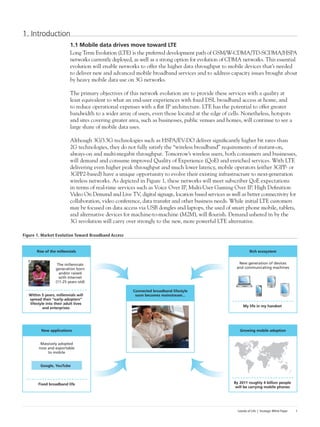
This document discusses the deployment of Long-Term Evolution (LTE) networks and the importance of in-building solutions to handle increasing mobile data traffic indoors. It notes that LTE will see its first deployments this year and will reinforce the "islands of life" concept by providing continuity of voice and data services in locations like workplaces, homes, malls and train stations. Providing quality in-building coverage presents challenges around architecture, design, installation, optimization and operations that require well-considered solutions. The document outlines best practices for selecting the right in-building LTE solution.

![Islands of Life | Strategic White Paper 7
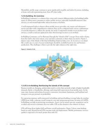
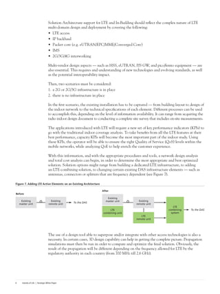
As an example, consider the simulation of LTE at 2.6 GHz on top of an already deployed active network
of UMTS 2.1 GHz (see Figure 8). Note that without changing the antenna positioning, the LTE
signal is strong enough to meet the coverage KPI. (In this case, the remote unit LTE delivered, in
fact, more output power than the UMTS, explaining the signal strength.)
Figure 8. Comparison Between UMTS and UMTS + LTE Propagation
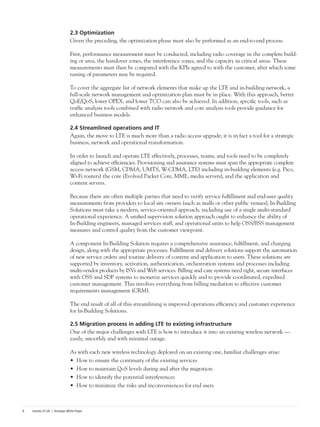
2.2 Installation and integration
What are the specific challenges of an LTE installation? LTE is a completely new end-to-end all-IP
architecture that will simplify the network design. Thus one of the major integration challenges is to
transform today’s architecture to full all-IP architecture. This will impact the end-to-end integration
process considerably in terms of upgrading the remote access and backhaul networks to deploy,
in parallel, the indoor solutions.
That makes expert and certified project management essential. The best project management
provides experienced resources to manage all components of the in-building solution, including
third-party components specified in the defined scope of the project, to ensure that key scheduling,
quality and budget objectives are met. Moreover, specific integration services may be required for
customer premises equipment (CPE), including PCs and laptops, PDAs, phones and other devices
and peripherals.
Technical analysis, implementation, roll-out and training must be adapted accordingly, as well
as help-desk preparation, and service level agreement (SLA) definition. Following are specific
considerations that could impact the integration phase:
• Integration of the DAS in the RAN IP network, such as Micro BTS, Pico BTS, and Femto,
including IP services (VPN data design and implementation)
• Adherence to local IT rules
• Security integration, such as encryption; strong authentication
• Specific fixed-mobile integration issues, such as development and integration of unified
communications, for example:
1. PBX and Virtual PBX functionalities integration
2. Audio, video and data conferencing integration
3. Wi-Fi and cellular integration
4. Dual-mode phone
5. RFID integration
• Specific applications integration, such as location-based services, M2M, and home networking
Before: UMTS After: UMTS + LTE
99.46[%] ≥ -78.00[dBm] 99.88[%] ≥ -78.00[dBm] 99.35[%] ≥ -78.00[dBm] 95.01[%] ≥ -78.00[dBm]](https://image.slidesharecdn.com/47eac2d6-62fb-4846-b0f2-bd8e4a0795d3-150508135310-lva1-app6891/85/LTE_Inbuilding_SWP-9-320.jpg)