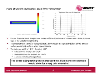
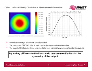
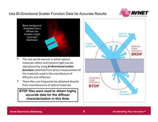
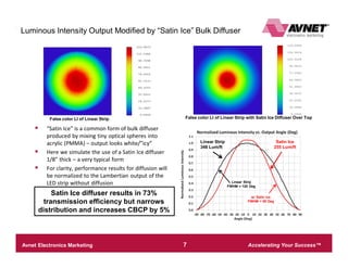
The document discusses simulations of linear LED lighting designs using various optical components like diffusers and reflectors. Key findings include:
1) A dense array of low-power LEDs can produce uniform illumination within 3.8mm. Diffusers were tested at this distance.
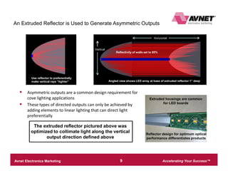
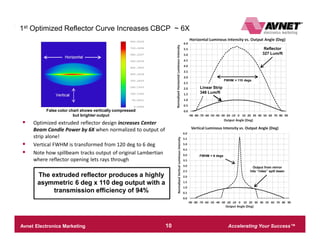
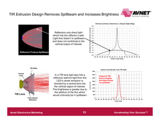
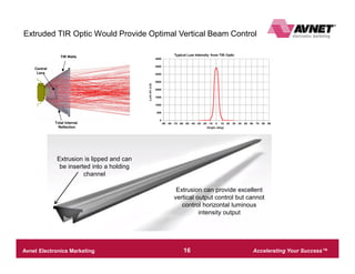
2) An extruded reflector designed to collimate light vertically produced a 6x110 degree beam, increasing brightness 6x over bare LEDs.
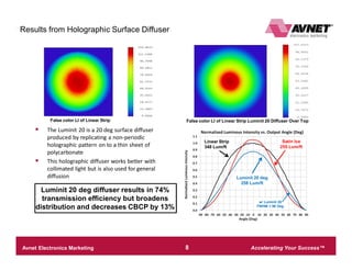
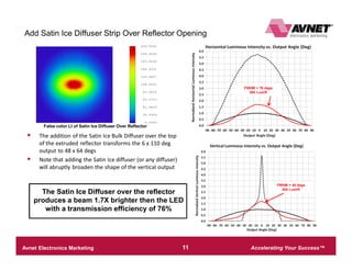
3) Adding a satin ice or holographic diffuser further broadened the beam to 48x64 and 40x84 degrees respectively, while maintaining high light output.
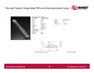
4) Total internal reflection lenses can further improve vertical beam control and brightness over reflectors.
1. Accelerating Your Success™Avnet Electronics Marketing – Company Confidential 1
Optical Simulation Details
Linear Lighting Design Notes
Extruded Reflectors and Diffusers
2. Accelerating Your Success™Avnet Electronics Marketing – Company Confidential 2
Optical Simulation DetailsLED Choice and Spacing Forms Basis for Linear Luminaire Design
§ Design goal is produce direct view linear cove lighting module
§ Choice is to use many low power LEDs
§ C8WT803 at a CCT of 3000K
§ “Dense array” spacing of 3.858 mm produces a plane of uniform
illuminance very close to LEDs
§ Allows for luminaire with very thin profile
§ With typical diffusion lumen density could be as high as 250
Lum/ft
C8WT803 array radiates into testing detector
Rayfile data allows
for accurate characterization
To model “real life” set output luminous flux = 4.5
Lum/LED for T(junction) ~ 85 C
3. Accelerating Your Success™Avnet Electronics Marketing – Company Confidential 3
Optical Simulation DetailsCharacterize Baseline Linear Array for Optical Performance
Illuminance
Luminous Intensity
4. Accelerating Your Success™Avnet Electronics Marketing – Company Confidential 4
Optical Simulation DetailsPlane of Uniform Illuminance at 3.8 mm From Emitter
§ Output from the linear array of LEDs shows uniform illuminance at a distance of 3.8mm from the
tops of the LEDs forming the strip
§ This means that if a diffuser were placed at 3.8 mm height the light distribution on the diffuser
surface would look uniform when viewed directly
§ The detector width is ~ 1.5” - length is 13.8”
§ Set output flux density = 351 Lum/ft
§ Measured output flux density is 348 Lum/ft
§ 3 lumens are lost due to edge effects
The dense LED packing which produced this illuminance distribution
would allow for a very thin luminaire!
5. Accelerating Your Success™Avnet Electronics Marketing – Company Confidential 5
Optical Simulation DetailsOutput Luminous Intensity Distribution of Baseline Array is Lambertian
§ Luminous intensity is a “far field” characterization
§ The component C8WT803 LEDs all have Lambertian luminous intensity profiles
§ The output of the baseline linear array must also have a circularly symmetrical Lambertian outputs
By adding diffusers to the linear strip one can modify the circular
symmetry of the output
6. Accelerating Your Success™Avnet Electronics Marketing – Company Confidential 6
Optical Simulation DetailsUse Bi-Directional Scatter Function Data for Accurate Results
§ The real world manner in which optical
materials reflect and transmit light can be
reproduced by using bi-directional scatter
functions obtained from direct measurement of
the materials used in the manufacture of
diffusers and reflectors
§ These files can frequently be obtained directly
from manufacturers of optical materials
BTDF files were used to obtain highly
accurate data for the diffuser
characterization in this Note
Black background
illustrates how a
diffuser can
broaden a tight
input light
distribution
7. Accelerating Your Success™Avnet Electronics Marketing – Company Confidential 7
Optical Simulation DetailsLuminous Intensity Output Modified by “Satin Ice” Bulk Diffuser
§ “Satin Ice” is a common form of bulk diffuser
produced by mixing tiny optical spheres into
acrylic (PMMA) – output looks white/”icy”
§ Here we simulate the use of a Satin Ice diffuser
1/8” thick – a very typical form
§ For clarity, performance results for diffusion will
be normalized to the Lambertian output of the
LED strip without diffusion
False color LI of Linear Strip False color LI of Linear Strip with Satin Ice Diffuser Over Top
Linear Strip
348 Lum/ft
Satin Ice
255 Lum/ft
Satin Ice diffuser results in 73%
transmission efficiency but narrows
distribution and increases CBCP by 5%
Linear Strip
FWHM = 120 Deg
w/ Satin Ice
FWHM = 90 Deg
8. Accelerating Your Success™Avnet Electronics Marketing – Company Confidential 8
Optical Simulation DetailsResults from Holographic Surface Diffuser
False color LI of Linear Strip False color LI of Linear Strip Luminit 20 Diffuser Over Top
§ The Luminit 20 is a 20 deg surface diffuser
produced by replicating a non-periodic
holographic pattern on to a thin sheet of
polycarbonate
§ This holographic diffuser works better with
collimated light but is also used for general
diffusion
Linear Strip
348 Lum/ft
Satin Ice
255 Lum/ft
Luminit 20 deg
258 Lum/ft
Luminit 20 deg diffuser results in 74%
transmission efficiency but broadens
distribution and decreases CBCP by 13%
w/ Luminit 20
FWHM = 96 Deg
9. Accelerating Your Success™Avnet Electronics Marketing – Company Confidential 9
Optical Simulation Details
An Extruded Reflector is Used to Generate Asymmetric Outputs
Use reflector to preferentially
make vertical rays “tighter”
Horizontal
Vertical
Angled view shows LED array at base of extruded reflector 1” deep
Extruded housings are common
for LED boards
Reflector design for optimum optical
performance differentiates products
§ Asymmetric outputs are a common design requirement for
cove lighting applications
§ These types of directed outputs can only be achieved by
adding elements to linear lighting that can direct light
preferentially
The extruded reflector pictured above was
optimized to collimate light along the vertical
output direction defined above
Reflectivity of walls set to 85%
10. Accelerating Your Success™Avnet Electronics Marketing – Company Confidential 10
Optical Simulation Details1st Optimized Reflector Curve Increases CBCP ~ 6X
False color chart shows vertically compressed
but brighter output
§ Optimized extruded reflector design increases Center
Beam Candle Power by 6X when normalized to output of
strip alone!
§ Vertical FWHM is transformed from 120 deg to 6 deg
§ Note how spillbeam tracks output of original Lambertian
where reflector opening lets rays through
Output from mirror
hits “rides” spill beam
FWHM = 6 degs
FWHM = 110 degs
Linear Strip
348 Lum/ft
Reflector
327 Lum/ft
The extruded reflector produces a highly
asymmetric 6 deg x 110 deg output with a
transmission efficiency of 94%
Horizontal
11. Accelerating Your Success™Avnet Electronics Marketing – Company Confidential 11
Optical Simulation DetailsAdd Satin Ice Diffuser Strip Over Reflector Opening
False color LI of Satin Ice Diffuser Over Reflector
FWHM = 48 degs
264 Lum/ft
FWHM = 76 degs
264 Lum/ft
§ The addition of the Satin Ice Bulk Diffuser over the top
of the extruded reflector transforms the 6 x 110 deg
output to 48 x 64 degs
§ Note that adding the Satin Ice diffuser (or any diffuser)
will abruptly broaden the shape of the vertical output
The Satin Ice Diffuser over the reflector
produces a beam 1.7X brighter then the LED
with a transmission efficiency of 76%
12. Accelerating Your Success™Avnet Electronics Marketing – Company Confidential 12
Optical Simulation DetailsAdd Luminit 20 Surface Diffuser to Comparison
§ The addition of the Luminit 20 Surface Diffuser over
the top of the extruded reflector now transforms the 6
x 110 deg output to 40 x 84 degs
§ Key observation is that now the Luminit 20 is more
efficient than the Satin Ice due to the light from the
extruded reflector being collimated
False color LI of Luminit 20 Diffuser Over Reflector
FWHM = 84 degs
281 Lum/ft
FWHM = 40 degs
281 Lum/ftThe Luminit 20/reflector combination
produces a beam 2X brighter then the LED
array alone with a transmission efficiency of
81%
13. Accelerating Your Success™Avnet Electronics Marketing – Company Confidential 13
Optical Simulation DetailsBeware - Peak Illuminance from Reflectors Could be an Issue!
§ Illuminance at diffuser plane shows lines that could
translate into possible objectionable hot regions for
direct view product (or be a “different design
feature”)
§ Note that for simulation only 85% reflectivity of
common aluminum was assumed – all reflective
bounces are specular – no BSDF data was used
Peak points
Output Illuminance of Reflector Extrusion at Top of Reflector
False Color image shows “hot” lux lines
“hot” lux peaks
created
by reflector walls
All reflective optics show regions of high
illuminance at the opening in front of the
reflector and may provide regions “too
hot” for direct view products
14. Accelerating Your Success™Avnet Electronics Marketing – Company Confidential 14
Optical Simulation Details
Output Illuminance of Reflector
Extrusion at Top of Reflector
with no Scatter
Output Illuminance of Reflector
Extrusion at Top of Reflector
with Known Scatter
Reflector Material with Known Diffusion Solves the Hot Spot Problem
Same reflector curves w/
same set of rays
Bottom curve has
known diffusion
Smoother illuminance shown in red curve results from
choosing a reflector with desired scattering properties
Choosing a reflective material with known diffusion in conjunction with intelligent
diffuser choice allows for linear lighting design which will hit asymmetric luminous
intensity targets while still satisfying direct view requirements
15. Accelerating Your Success™Avnet Electronics Marketing – Company Confidential 15
Optical Simulation Details
Total Internal
Reflection
TIR Walls
Central
Lens
TIR Extrusion Design Removes Spillbeam and Increases Brightness
Reflectors only direct light
which hits the reflector’s wall.
Light that doesn’t is spillbeam
and does not contribute to the
vertical output of interest.
In a TIR lens light also hits a
reflective wall but light from the
LED’s center emission is
directed by a central lens into
the vertical region of interest.
The brightness is greater due to
the addition of the flux which
would ordinarily be in spillbeamTIR Lens
Output of TIR
lens is brighter
and base shows
no spillbeam
Reflectors Produce Spillbeam
16. Accelerating Your Success™Avnet Electronics Marketing – Company Confidential 16
Optical Simulation Details
Total Internal
Reflection
TIR Walls
Central
Lens
Extruded TIR Optic Would Provide Optimal Vertical Beam Control
Extrusion is lipped and can
be inserted into a holding
channel
Extrusion can provide excellent
vertical output control but cannot
control horizontal luminous
intensity output
17. Accelerating Your Success™Avnet Electronics Marketing – Company Confidential 17
Optical Simulation DetailsSummary and Discussion
§ The very dense linear array of low power LEDs was able to produce a light engine capable of “fast” uniform
illuminance:
§ Uniform illuminance was achieved at only 3.8 mm above the plane of the top of the LED packages
§ Output flux density was calculated at a realistic 351 Lum/W
§ For the linear light engine diffusers were placed at 3.8 mm distance and characterized for transmission efficiency
and luminous intensity output distribution
§ A bulk Satin Ice Diffuser produced an output with a FWHM = 90 deg at 73% transmission efficiency which was 5%
brighter than the strip output alone
§ The Luminit 20 surface diffuser yielded a FWHM = 96 deg with 74% transmission efficiency with a CPBP 13 %
dimmer than the strip output
§ The tighter FWHM of the Satin Ice Diffuser accounts for this difference in brightness given similar transmission
efficiencies
§ To create asymmetric distributions an extruded reflector was designed to optimize vertical output asymmetry
and brightness and was then used with the same two diffusers outlined above
§ The extrusion itself produced an output of 6 x 110 degrees with a transmission efficiency of 94%
§ With a satin ice bulk diffuser cover the output changed to 48 x 64 degrees with a brightness peak 1.7X brighter than
the light engine Lambertian output alone (transmission efficiency = 76%)
§ The Luminit 20 surface diffuser produced an output of 40 x 84 degrees which was 2X as bright as the baseline
Lambertian (with a transmission efficiency of 81%)
§ Note that because of the collimated output coming from the vertical part of the distribution the holographic Luminit 20
diffuser bested the Satin Ice bulk diffuser
§ An extruded TIR lens can be used to redirect spillbeam and provide even greater vertical beam control and
brightness
19. Accelerating Your Success™Avnet Electronics Marketing – Company Confidential 19
Optical Simulation DetailsThe Ledil “Sophie” Single-Sided TIR Lens Gives Asymmetric Output
20. Accelerating Your Success™Avnet Electronics Marketing – Company Confidential 20
Optical Simulation DetailsOptical Characterization of Sophie Using IES File
Polar Detector
Centered on IES file
21. Accelerating Your Success™Avnet Electronics Marketing – Company Confidential 21
Optical Simulation Details
Luminous Intensity Slice Shows Output Directed Up at 20 Deg
Optic also spills
light down and
forward
22. Accelerating Your Success™Avnet Electronics Marketing – Company Confidential 22
Optical Simulation Details
Luminit Redirecting Film Based on Beam Shifting Prisms
§ Since redirection is achieved by using beam shifting
prisms the effect is optimum for directed light beams
§ Best use is in front of a spotlight
§ Light with wider beam angles may show peculiar,
“dispersive” type of results since tighter beam angles will
be redirected better than wider beam angles