There are many Power LED lens manufacturers worldwide. Each of them is producing lenses for determined types and manufacturers of Power LED. LED are all different so that one lens can be used on only one LED. From experience gained in the last months, we can say that a significant part of these lenses are not so dedicated and the results are quite different from expectations. When measuring lenses in combination with adequate LED we focused our attention on efficacy, repeatability, consistency with the nominal data and problems with the installation.
• How low-e coatings work• The differences between “passive” and “solar control” low-e coatings• How the energy, environmental and economic benefits of low-e glass have been quantified• The energy impact of various low-e coated glass through simulation modeling
Here is the presentation that Kevin L. Willmorth and I gave on Using AR Glass for Lighting to the IES\' 2011 Annual Convention in Austin, TX on October 31st.
For the full video of this presentation, please visit:
https://www.embedded-vision.com/platinum-members/embedded-vision-alliance/embedded-vision-training/videos/pages/may-2017-embedded-vision-summit-gehlhar
For more information about embedded vision, please visit:
http://www.embedded-vision.com
Jessica Gehlhar, Vision Solutions Engineer at Edmund Optics, presents the "Introduction to Optics for Embedded Vision" tutorial at the May 2017 Embedded Vision Summit.
This talk provides an introduction to optics for embedded vision system and algorithm developers. Gehlhar begins by presenting fundamental imaging lens specifications and quality metrics. She explains key parameters and concepts such as field of view, f number, working f number, NA (numerical aperture), focal length, working distance, depth of field, depth of focus, resolution, MTF (modulation transfer function), distortion, keystoning, and telecentricity and their relationships. Optical design basics and trade-offs introduced include design types, aberrations, aspheres, pointing accuracy, sensor matching, color and protective coatings, filters, temperature and environmental considerations, and their relation to sensor artifacts.
She also explores manufacturing considerations, including testing the optical components and imaging lenses in a product, and the industrial optics used for a wide range of manufacturing tests. Depending on requirements, a wide variety of tests and calibrations may be performed. These tests and calibrations become important with designs that include technologies such as multi-camera, 3D, color and NIR (near-infrared).
electrical luminaries and market surveysahil saifi
A luminaire is defined in Article 100 as “a complete lighting unit consisting of a lamp or lamps together with the parts designed to distribute the light, to position and protect the lamps and ballast (where applicable), and to connect the lamps to the power supply.” Since luminaires (lighting fixtures) were not previously defined before the 2002 NEC, this new definition is meant to cover all aspects of a lighting unit, including the lamps that actually provide the illumination, as well as internal and external parts necessary for the proper operation of the unit.
Physically Based Lighting in Unreal Engine 4Lukas Lang
Talk held at Unreal Meetup Munich on 15th May 2019.
I talked about some of the theoretical background of physically based lighting, demonstrated a workflow + containing value tables needed to be able to easily use the workflow.
Epic Games Japan hold a meeting named "Lightmass Deep Dive" on July 30, 2016.
A Japanese architectural artist, Kenichi Makaya, created Casa Barragan on UE4. the architecture is a house of Mexican Architect, Luis Barragan. And he gave a presentation about making of the scene. .
CASA BARRAGAN Unreal Engine4
https://www.youtube.com/watch?v=Y7r28nO4iDU&feature=youtu.be
EGJ translated the slide for the presentation to English and published it.
Diode Dynamics LED Lighting Engineering WhitepaperMatthew Conte
An overview of the current state of the art in LED Light Bars, focusing on lumens, lux, candella, beam patterns, as well as an in depth analysis of the ideal beam pattern for rally racing.
The working principle of HID lamp and LED are different, the light spectrums of them are different, both of them have advantages and disadvantages, let's check of them deeper and understanding better.
Residential Applications for LED Lighting: How LED lighting is creating opportunities for creating dynamic lighting layering in residential spaces
LEARNING OUTCOMES
To better understand the key benefits of using LED lighting in residential applications.
To better understand how LED technology is positively impacting lighting design objectives when using lighting layers.
To better understand the specific benefits of LED lighting in kitchen and baths.
To better understand the primary specification issues that designers and architects must define when selecting and applying LED decorative and architectural lighting in residential applications.
To analyze specific case studies of successful LED lighting application.
This session is proudly sponsored by Residential Lighting
Presented by: Joseph A. Rey-Barreau, AIA, IES, i
The crucial point to contemplate during restorative dentistry procedures with composite resins is to obtain satisfactory restorations with an adequate photo polymerization technique. This procedure requires sufficient light energy intensity and an adequate wavelength in order to activate the photo initiator within these materials, which will react with the reducer agent to form free radicals and initiate the polymerization process.
1. Furlan, Kobav, Širca:„Choosing lenses for Power LED based luminaire“
Choosing lenses for Power LED based luminaire
V. Furlan M. Kobav, D. Širca
Abstract
When designing a Power LED lighting fitting, choosing a optimal secondary lens is of
crucial importance. The appropriate lens or reflector is determined on the basis of dimensions
of luminare body, availability of adequate beam angle and price. At first glance, the task
seems very simple, however, when solving the problem practically, many problems arise.
There are many Power LED lens manufacturers worldwide. Each of them is producing
lenses for determined types and manufacturers of Power LED. LED are all different so that
one lens can be used on only one LED. From experience gained in the last months, we can
say that a significant part of these lenses are not so dedicated and the results are quite
different from expectations. When measuring lenses in combination with adequate LED we
focused our attention on efficacy, repeatability, consistency with the nominal data and
problems with the installation.
1. Power LED properties
High efficiency and lower energy consumption compared to the classical bulbs, halogen
bulbs and in last months even fluorescence lamps are leading to ever higher popularity of
Power LED as a lighting source. Another, often neglected, advantage of LED is its
directionality. When other types of lighting sources emit light in all directions and so
intrinsically increase losses, LED have a beam angle between 90° and 120°.
Because of this the lighting fitting can be designed to radiate light in the desired direction
with almost no reflective loss.
Even so, in most cases the LED beam angle is usually to wide to be used in an lighting
fixture without some secondary optics reducing the angle to a acceptable value. This is
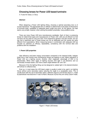
usually done with the use of secondary optics, reflectors (figure 2) and lenses (figure 1), made
by specialized manufacturers in vast numbers. Because of price they are rarely custom made.
Figure 1. Power LED lenses
1
2. Furlan, Kobav, Širca:„Choosing lenses for Power LED based luminaire“
Figure 2. Power LED reflectors
The most common secondary optics are reflectors and Total Internal Reflection (TIR)
optic. Reflectors produce very wide beams, have good efficiency (> 90%) and have a sharp
beam edge.
TIR it is a compound optic that uses a combination of a central lens and TIR mirror to
collimate the light from the source (figure 3 and 4).
TIR is an optical phenomenon that occurs when a ray of light strikes a medium boundary
at an angle larger than the critical angle with respect to the normal of the surface. If the
refractive index is lower on the other side of the boundary no light can pass through, so
effectively all of the light is reflected. When light crosses a boundary between materials with
different refractive indices, the light beam will be partially refracted at the boundary surface,
and partially reflected. However, if the angle of incidence is greater than the critical angle,
than the light will stop crossing the boundary altogether and instead be totally reflected back
internally. This can only occur where light travels from a medium with a higher refractive index
to one with a lower refractive index.
Figure 3. Light ray paths through a TIR optic
Figure 4. light ray paths through a TIR optic regarding incidence angle
2
3. Furlan, Kobav, Širca:„Choosing lenses for Power LED based luminaire“
Secondary optics are characterised by how wide a beam they produce. The angular width
the optics produce is usually specified by measuring the angular separation between the
directions, at which the intensity has fallen to half its peak value. The value is called the Full
Width Half Maximum (FWHM) divergence.
Figure 5. Full Width Half Maximum Angle definition
When mounting secondary optics positioning the optics at the correct height relative to the
LED is essential if you are to obtain best efficiency and the correct beam width. Equally
important is the alignment of the optic axis to the LED chip. If not correctly positioned, the
output beam will become uneven and offset. Although a industrial standard doesn’t exist, a
commune accuracy is ± 0.2 mm.
Lens producers usually supply a range of holders for a single emitter LED, starboard
mounted LED and various versions of multiple lenses. Although solving part of the problem,
holders usually have the same ± 0.2 mm accuracy, so for narrow spot they might not be the
perfect solution.
Figure 6. LED, lens, holder assembly
2. Lens comparision
In the first part we measured lens efficacy regarding the forward current trough the LED.
Then we compared lenses of different manufacturers, and we tested the repetibility of lenses
of the same manufacturer. At the end we tested what happens when bad holder is used and
focus is moved.
3
4. Furlan, Kobav, Širca:„Choosing lenses for Power LED based luminaire“
2.1. Dependence of luminous intensity on the forward current
To control behaviour of the lens under different forward current, measurement was made
using one lens on a LED with different forward current applied. Forward current of 700mA and
1A were used on Seoul P4 and Cree Xr-E LED. In both cases 1A is the maximum current that
could be applied to the LED without damaging it. LED with its lens was installed on a big
disipator and the complete set was then installed on a fotogoniometer.
In the case of Seoul P4 with 9.5 peak at 700mA is at 1998 cd, and 2520 cd at 1A. The
ratio is 1.26. Ratio of the forward current is 1.43. Lower efficiency is due to the higher junction
temperature. Despite a large disipator the junction temperature has risen and the efficiency
droped.
In the case of Cree and 36 lens at 700mA peak is at 346 cd, and 436 cd for 1A. The flux
ratio is also 1.26 and current ratio 1.43. Again there is a small difference which can be led to
the higher junction temperature.
From this measurements can be concluded that lenses behave identically at different
forward currents and when measuring them only one forward current can be applied. From
there other values can be calculated, taking care to include junction temperature in the
calculus. Dependance of luminous flux of LED of junction temperature can be obtained from
the manufacturer.
Figure 7: Dependance of iluminance of the forward current
2.2. Comparison of lenses of different manufacturers
The next task was to measure and compare lenses of different manufacturers and same
beam angles.
We compared lenses of three manufacturers for Cree XR-E with 8 FWHM. The difference
between lenses are immediately visible. The highest luminance (5810 cd) is 35% higher than
lowest (4310 cd). The comparision diagram is shown on figure 8.
4
5. Furlan, Kobav, Širca:„Choosing lenses for Power LED based luminaire“
Figure 8: Relative luminace with lenses (8º) of three different manufacturers (Cree Xr-E)
On the second diagram narrow beam lenses (10) of the same manufacturers for Seoul P4
LED are compared. Measured luminances are from 1415 cd to 2100 cd. So, for this lenses
the differences are big, more than 50% between the best and worst.
Figure 9: Relative luminace with lenses (10º) of three different manufacturers (Seoul P4)
On third diagram wide beam lenses (40) for Seoul P4 are compared. Measured
luminances are 278 cd, 296 cd and 332 cd. The differences are smaller but nonetheless
significant.
Figure 10: Relative luminace with lenses (40º) of three different manufacturers (Seoul P4)
In our measurements we found that differences between the lenses manufacturers are big
and that “good” manufacturer name doesn’t guarantee good lenses. In our measurements,
5
6. Furlan, Kobav, Širca:„Choosing lenses for Power LED based luminaire“
namely, lenses form an unknown Chinese manufacturer were better than lenses form a well
known European manufacturer, which is about twice as expensive.
2.3. Impact of the lens diameter
We measured the lenses of the same manufacturer but of different diameter. We expected
to get better results from the bigger lens. We have to know that the small lens is a
compromise between the requirements of lighting designers, who need small dimensions,
and engineers who know that a optimal lighting efficiency need adequate space. We
measured lenses with 20mm and 26mm diameter (which are something standard
dimensions).
For a broad angle lenses (about 40) difference between luminance is small (296 cd and
360 cd)(figure 11). Here, we must bear in mind that the lens with smaller luminance has
broader angle (2.2) and therefore the lower luminance at 0 is justified. So the light yield is
practically identical.
At narrow angle (10) the difference is huge, 2460 cd and 1415 cd. This is 73% difference
(figure 12).
Figure 12: Relative luminace with lenses (40º) of different dimensions (Seoul P4)
Figure 12: Relative luminace with lenses (10º) of different dimensions (Seoul P4)
The measurements confirm the assumption that bigger lens have greater efficiency.
6
7. Furlan, Kobav, Širca:„Choosing lenses for Power LED based luminaire“
2.4. The problem of lens positioning
In order to have a perfect symmetric light distribution LED has to be positioned as precise
as possible. On the figure 13. a) and b) light emitted form a white object illuminated with
power Led luminare is shown.
Figure 13. Surface illuminated with LED with incorrectly positioned lens (10°)
As it can be seen, maximum light is not in the centre of the illuminated surface. This is due
to the error in positioning. First probable error is the movement of the lens, which has a small
possibility of movement, about 0.2 mm. The second error arise when the starboard is screwed
in the housing. It is not possible to estimate how much the LED has moved, but the
displacement is minimal. The same effect can be seen but using broad angle lens (figure 14).
Figure 14. Surface illuminated with LED with incorrectly positioned lens (40°)
Conclusion
In this article several problems regarding secondary lenses for power LED were analysed.
The biggest problem is certainly the choice of the lens. With measurements we found that
different manufacturers have lenses of different quality for different power LED and different
angles. We found that it is possible that a certain manufacturer has excellent narrow angle
lens and bad broad angle lens. Because of this phenomenon it is difficult to determine which
manufacturer has the best overall lenses. Practically, this means that to choose the lens for
power LED, we have to measure all lenses and all angles and make a compromise.
As far a diameter of the lens goes, for narrow angles bigger diameter should be used. For
wide angles, diameter is purely a design element.
7
8. Furlan, Kobav, Širca:„Choosing lenses for Power LED based luminaire“
At the end a problems arising from less than perfect alignment of lens and LED were
examined. As a small non-alignment can lead to significant errors in the enlighten surface.
Positioning of narrow angle optics proved even more difficult. It is advised to use specially
designed holders should be used whenever possible.
Authors:
Vladimir Furlan
Intra Lighting d.o.o.
Miren 137b, Miren, Slovenia
+386 (0)5 398 44 58
Vladimir.furlan@intra-lighting.com
Matej B. Kobav
University of Ljubljana – Faculty of Electrical Engineering,
Tržaška 25, Ljubljana, Slovenia
+386 (0)1 476 87 59
matej.kobav@fe.uni-lj.si
Davor Širca
Intra Lighting d.o.o.
Miren 137b, Miren, Slovenia
+386 (0)5 398 44 54
Davor.sirca@intra-lighting.com
8