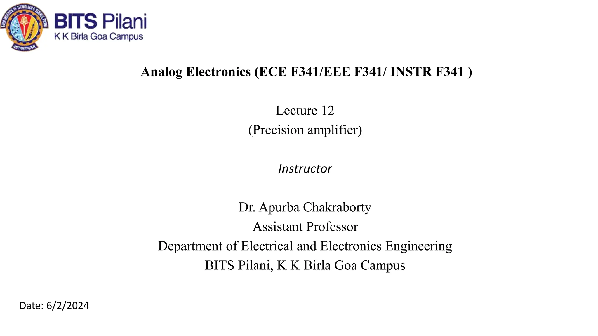
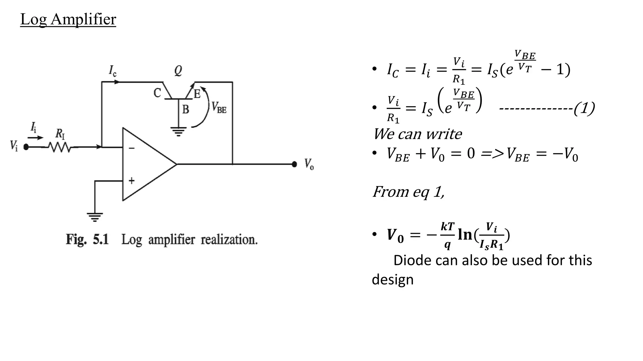
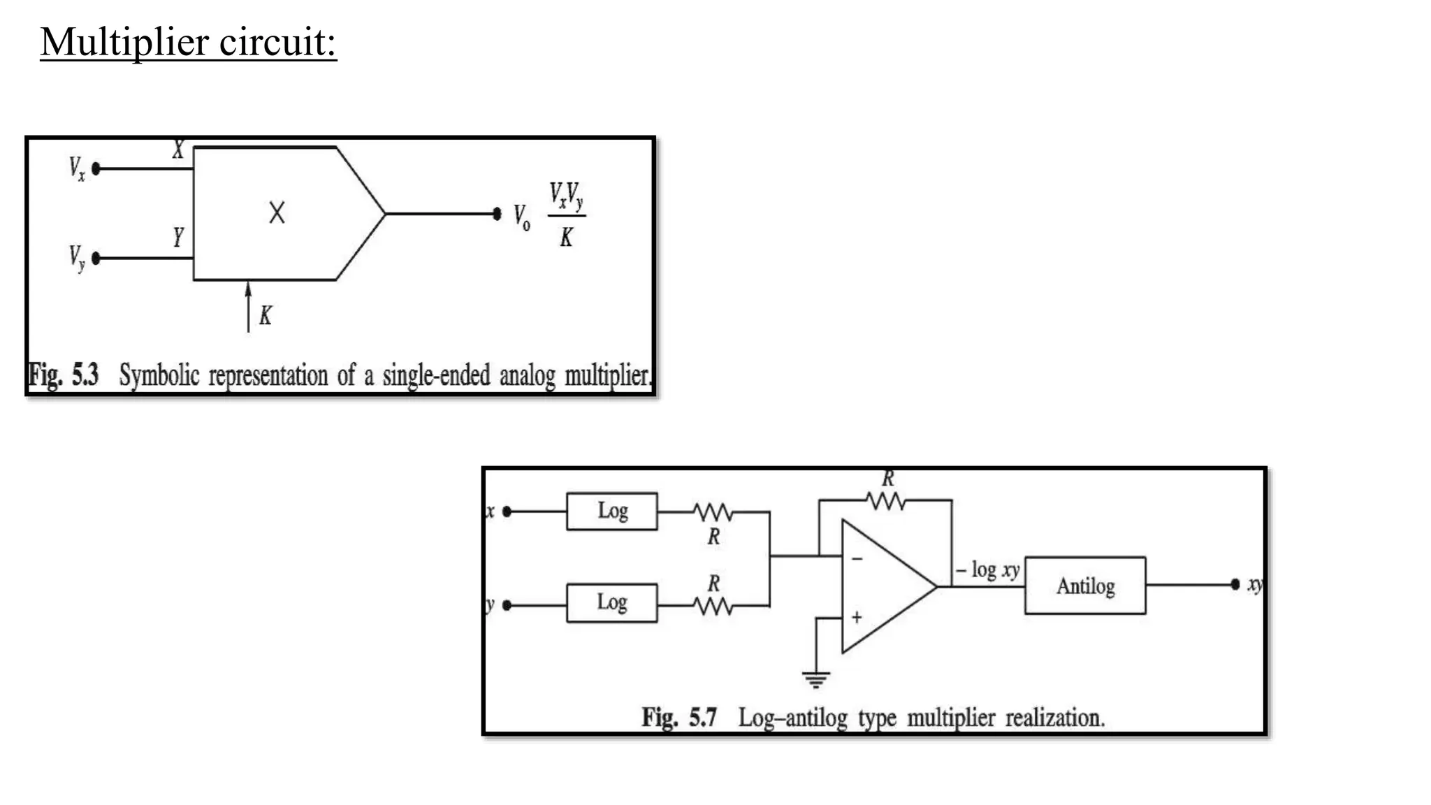
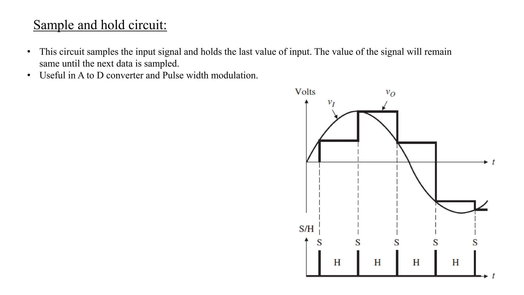
Analog Electronics (ECE F341/EEE F341/ INSTR F341 )
Lecture 12
(Precision amplifier)
Instructor
Dr. Apurba Chakraborty
Assistant Professor
Department of Electrical and Electronics Engineering
BITS Pilani, K K Birla Goa Campus
Date: 6/2/2024
Log Amplifier
• 𝐼𝐶 = 𝐼𝑖 =
𝑉𝑖
𝑅1
= 𝐼𝑆(𝑒
𝑉𝐵𝐸
𝑉𝑇 − 1)
•
𝑉𝑖
𝑅1
= 𝐼𝑆 𝑒
𝑉𝐵𝐸
𝑉𝑇 --------------(1)
We can write
• 𝑉𝐵𝐸 + 𝑉0 = 0 => 𝑉𝐵𝐸 = −𝑉0
From eq 1,
• 𝑽𝟎 = −
𝒌𝑻
𝒒
𝐥𝐧(
𝑽𝒊
𝑰𝒔𝑹𝟏
)
Diode can also be used for this
design
Antilog amplifier
𝑉𝑖𝑛 = −𝑉𝐵𝐸 -------------------(1)
𝐼𝑖 = 𝐼𝑆 𝑒
𝑉𝐵𝐸
𝑉𝑇 − 1 = 𝐼𝑆 𝑒
−𝑉𝑖𝑛
𝑉𝑇 =
𝑉0
𝑅𝐹
=> 𝑽𝟎 = 𝑹𝑭𝑰𝑺𝐞𝐱𝐩
−𝒒𝑽𝒊
𝒌𝑻
= 𝑹𝑭𝑰𝑺 (antilog(
−𝒒𝑽𝒊
𝒌𝑻
)
Multiplier circuit:
Division circuit:
𝑉𝑍 = −𝑉1 --------(1)
𝑉1= K𝑉𝑋𝑉0 = −𝑉𝑍
𝑽𝟎 =
−𝑽𝒁
𝑲𝑽𝑿
Square root circuit:
𝑉𝑍 − 0 = 0 − 𝑉1 --------(1)
𝑉1= K𝑉0𝑉0 = −𝑉𝑍
if the magnitude is negative
𝑉0= 𝑉𝑍 /𝐾
So the input no must be negative.
Amplitude modulation
(
𝑉𝑚𝐸𝑐𝐶𝑜𝑠 ω𝑡
𝐾
− 𝑉𝑋)𝑚𝐾 = 𝑉𝑋- 𝐸𝑐𝐶𝑜𝑠 ω𝑡
=> 𝑚𝑉
𝑚𝐸𝑐𝐶𝑜𝑠 ω𝑡 + 𝐸𝑐𝐶𝑜𝑠 ω𝑡 = 𝑉𝑋+𝑉𝑋mK-----------(1)
we can write
𝑉
𝑜 = 1 + 𝑚𝐾 𝑉𝑋
= 𝑚𝑉
𝑚𝐸𝑐𝐶𝑜𝑠 ω𝑡 + 𝐸𝑐𝐶𝑜𝑠 ω𝑡 from eq 1.
This is AM signal.
Sample and hold circuit:
• This circuit samples the input signal and holds the last value of input. The value of the signal will remain
same until the next data is sampled.
• Useful in A to D converter and Pulse width modulation.
Track and Hold circuit
In Sample and hold circuit, the input voltage is captured
instantaneously . But, in real the instantaneously capturing
of voltage is unfeasible due to inherent dynamic limitation
of physical circuits.
Track and Hold circuit
Switches
Use of Switch in Multiplexing
Four quadrant Multiplier:
This is the general multiplier circuit
characteristics.
It is called four quadrant Multiplier.
Multiplier design by Variable transcoductance amplifier
By proper design ,
K= 1/10 V
𝑉0 = 𝑉𝑍1 − 𝑉𝑍2
𝑉𝑋 = 𝑉𝑋1 − 𝑉𝑋2
𝑉𝑌 = 𝑉𝑌1 − 𝑉𝑌2
Variety of monolithic multiplier
like
AD534 and MPY 100.
Applications:
• Modulation and demodulation
• Analog computation
• Phase detection etc.
At low pass filter, all high frequency components are suppressed
This circuit can be a phase detector or ac power computation circuit.
Four quadrant Divider
Four quadrant square root

Lecture12_log amplifier_s_h circuit_switches_6 Feb.pptx

  • 2.
    Analog Electronics (ECEF341/EEE F341/ INSTR F341 ) Lecture 12 (Precision amplifier) Instructor Dr. Apurba Chakraborty Assistant Professor Department of Electrical and Electronics Engineering BITS Pilani, K K Birla Goa Campus Date: 6/2/2024
  • 3.
    Log Amplifier • 𝐼𝐶= 𝐼𝑖 = 𝑉𝑖 𝑅1 = 𝐼𝑆(𝑒 𝑉𝐵𝐸 𝑉𝑇 − 1) • 𝑉𝑖 𝑅1 = 𝐼𝑆 𝑒 𝑉𝐵𝐸 𝑉𝑇 --------------(1) We can write • 𝑉𝐵𝐸 + 𝑉0 = 0 => 𝑉𝐵𝐸 = −𝑉0 From eq 1, • 𝑽𝟎 = − 𝒌𝑻 𝒒 𝐥𝐧( 𝑽𝒊 𝑰𝒔𝑹𝟏 ) Diode can also be used for this design
  • 4.
    Antilog amplifier 𝑉𝑖𝑛 =−𝑉𝐵𝐸 -------------------(1) 𝐼𝑖 = 𝐼𝑆 𝑒 𝑉𝐵𝐸 𝑉𝑇 − 1 = 𝐼𝑆 𝑒 −𝑉𝑖𝑛 𝑉𝑇 = 𝑉0 𝑅𝐹 => 𝑽𝟎 = 𝑹𝑭𝑰𝑺𝐞𝐱𝐩 −𝒒𝑽𝒊 𝒌𝑻 = 𝑹𝑭𝑰𝑺 (antilog( −𝒒𝑽𝒊 𝒌𝑻 )
  • 5.
  • 6.
    Division circuit: 𝑉𝑍 =−𝑉1 --------(1) 𝑉1= K𝑉𝑋𝑉0 = −𝑉𝑍 𝑽𝟎 = −𝑽𝒁 𝑲𝑽𝑿
  • 7.
    Square root circuit: 𝑉𝑍− 0 = 0 − 𝑉1 --------(1) 𝑉1= K𝑉0𝑉0 = −𝑉𝑍 if the magnitude is negative 𝑉0= 𝑉𝑍 /𝐾 So the input no must be negative.
  • 8.
  • 9.
    ( 𝑉𝑚𝐸𝑐𝐶𝑜𝑠 ω𝑡 𝐾 − 𝑉𝑋)𝑚𝐾= 𝑉𝑋- 𝐸𝑐𝐶𝑜𝑠 ω𝑡 => 𝑚𝑉 𝑚𝐸𝑐𝐶𝑜𝑠 ω𝑡 + 𝐸𝑐𝐶𝑜𝑠 ω𝑡 = 𝑉𝑋+𝑉𝑋mK-----------(1) we can write 𝑉 𝑜 = 1 + 𝑚𝐾 𝑉𝑋 = 𝑚𝑉 𝑚𝐸𝑐𝐶𝑜𝑠 ω𝑡 + 𝐸𝑐𝐶𝑜𝑠 ω𝑡 from eq 1. This is AM signal.
  • 10.
    Sample and holdcircuit: • This circuit samples the input signal and holds the last value of input. The value of the signal will remain same until the next data is sampled. • Useful in A to D converter and Pulse width modulation.
  • 12.
    Track and Holdcircuit In Sample and hold circuit, the input voltage is captured instantaneously . But, in real the instantaneously capturing of voltage is unfeasible due to inherent dynamic limitation of physical circuits.
  • 13.
  • 14.
  • 15.
    Use of Switchin Multiplexing
  • 16.
    Four quadrant Multiplier: Thisis the general multiplier circuit characteristics. It is called four quadrant Multiplier.
  • 17.
    Multiplier design byVariable transcoductance amplifier By proper design , K= 1/10 V 𝑉0 = 𝑉𝑍1 − 𝑉𝑍2 𝑉𝑋 = 𝑉𝑋1 − 𝑉𝑋2 𝑉𝑌 = 𝑉𝑌1 − 𝑉𝑌2 Variety of monolithic multiplier like AD534 and MPY 100.
  • 18.
    Applications: • Modulation anddemodulation • Analog computation • Phase detection etc. At low pass filter, all high frequency components are suppressed This circuit can be a phase detector or ac power computation circuit.
  • 19.
    Four quadrant Divider Fourquadrant square root