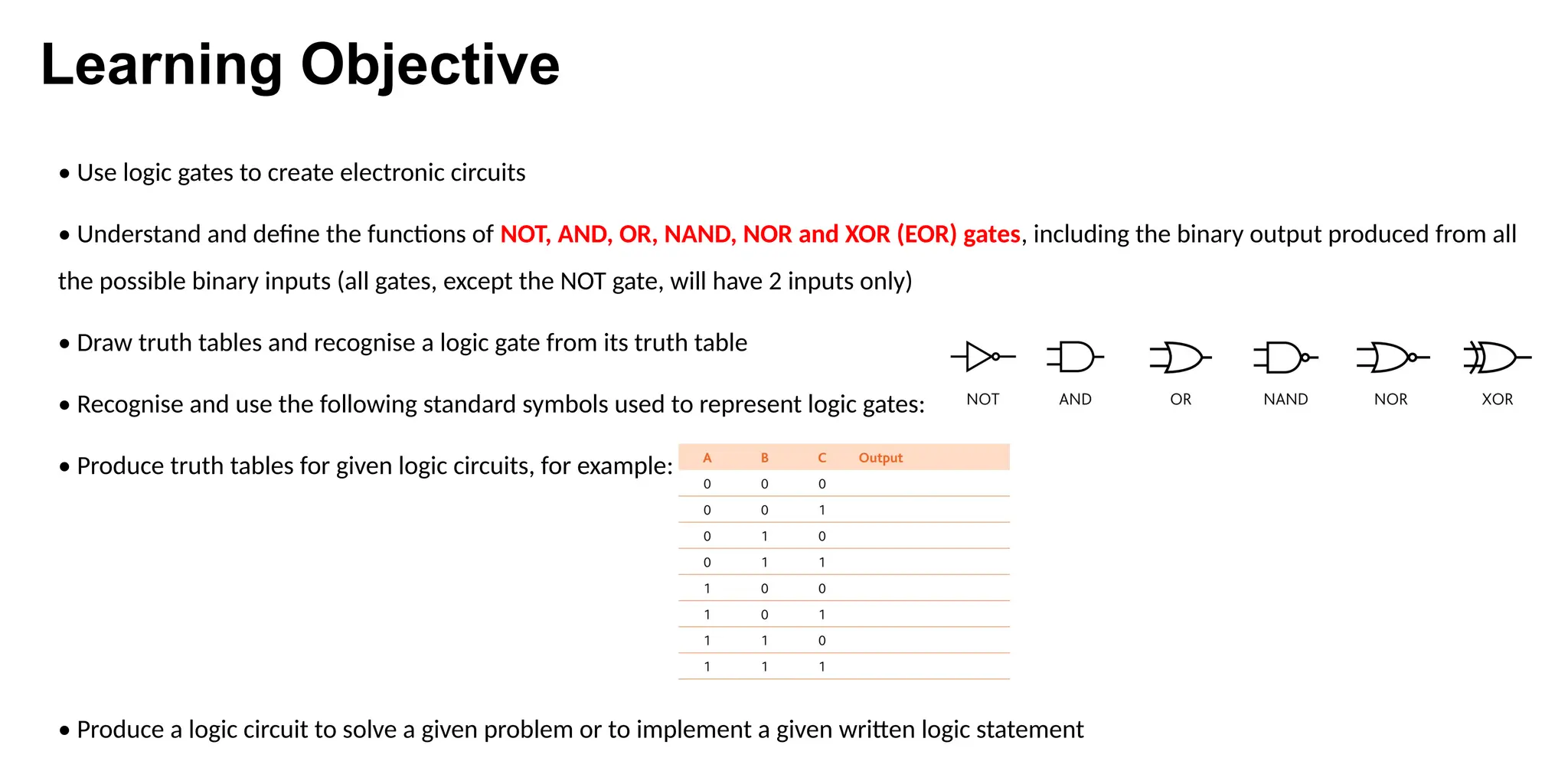
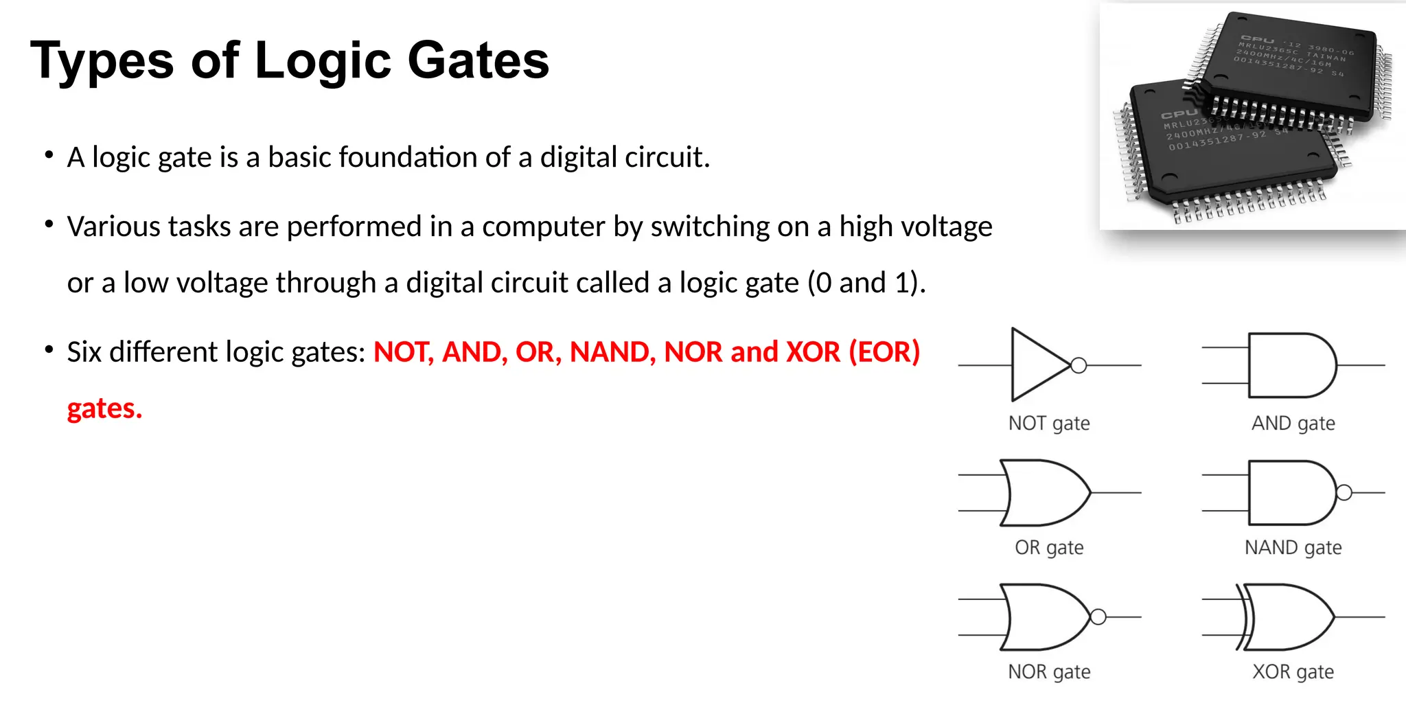
Chapter-4 Logic Gates
SUPERVISED BY
FARHAD AHMED
LECTURER OF ICT and CS
Learning Objective
• Use logic gates to create electronic circuits
• Understand and define the functions of NOT, AND, OR, NAND, NOR and XOR (EOR) gates, including the binary output produced from all
the possible binary inputs (all gates, except the NOT gate, will have 2 inputs only)
• Draw truth tables and recognise a logic gate from its truth table
• Recognise and use the following standard symbols used to represent logic gates:
• Produce truth tables for given logic circuits, for example:
• Produce a logic circuit to solve a given problem or to implement a given written logic statement
Types of Logic Gates
• A logic gate is a basic foundation of a digital circuit.
• Various tasks are performed in a computer by switching on a high voltage
or a low voltage through a digital circuit called a logic gate (0 and 1).
• Six different logic gates: NOT, AND, OR, NAND, NOR and XOR (EOR)
gates.
Truth Table
• Truth tables are used to trace the output from a logic gate or logic circuit. The NOT gate is the
only logic gate with one input; the other five gates have two inputs.
• Each logic gate can only have one or two inputs, the number of inputs to a logic circuit can be
more than 2; for example, three inputs give a possible 23
(=8) binary combinations. And for four
inputs, the number of possible binary combinations is 24
(=16).
Truth Table Continue
The function of the six logic gates
• NOT gate-
The function of the six logic gates
• AND gate-
The function of the six logic gates
• NAND gate (NOT AND)-
The function of the six logic gates
• OR gate-
The function of the six logic gates
• NOR gate (NOT OR)-
The function of the six logic gates
• XOR gate-
Logic circuits
• Creating a truth table for a logic circuit-
Logic circuits
• Creating a truth table for a logic circuit-
Creating a circuit diagram from a logic statement
• Example-1:- X= NOT(A OR B)
Creating a circuit diagram from a logic statement
• Example-2:- X= (NOT C) AND (A OR B)
1.
2.
3.
4.
Example of logic gates with statement
• A safety system uses three inputs to a logic circuit. An alarm, X, sounds if input A represents ON
and input B represents OFF; or if input B represents ON and input C represents OFF. Produce a
logic circuit and truth table to show the conditions that cause the output X to be 1.
Example of logic gates with statement
• A wind turbine has a safety system which uses three inputs to a logic circuit. A certain
combination of conditions results in an output, X, from the logic circuit being equal to 1. When
the value of X = 1 then the wind turbine is shut down. The following table shows which
parameters are being monitored and form the three inputs to the logic circuit.
Example of logic gates with statement (Cont)
• The output, X, will have a value of 1 if any of the following
combination of conditions occur:
• Either turbine speed <= 1000 rpm and bearing temperature > 80°C
• Or turbine speed > 1000 rpm and wind velocity > 120 kph
• Or bearing temperature <= 80°C and wind velocity > 120 kph
• Design the logic circuit and complete the truth table to
produce a value of X = 1 when either of the three
conditions above occur.
Example of logic gates with statement (Cont)
THANK YOU
&
Any Questions?

Lecture-4 Logic Gates about the output device

  • 1.
    Chapter-4 Logic Gates SUPERVISEDBY FARHAD AHMED LECTURER OF ICT and CS
  • 2.
    Learning Objective • Uselogic gates to create electronic circuits • Understand and define the functions of NOT, AND, OR, NAND, NOR and XOR (EOR) gates, including the binary output produced from all the possible binary inputs (all gates, except the NOT gate, will have 2 inputs only) • Draw truth tables and recognise a logic gate from its truth table • Recognise and use the following standard symbols used to represent logic gates: • Produce truth tables for given logic circuits, for example: • Produce a logic circuit to solve a given problem or to implement a given written logic statement
  • 3.
    Types of LogicGates • A logic gate is a basic foundation of a digital circuit. • Various tasks are performed in a computer by switching on a high voltage or a low voltage through a digital circuit called a logic gate (0 and 1). • Six different logic gates: NOT, AND, OR, NAND, NOR and XOR (EOR) gates.
  • 4.
    Truth Table • Truthtables are used to trace the output from a logic gate or logic circuit. The NOT gate is the only logic gate with one input; the other five gates have two inputs. • Each logic gate can only have one or two inputs, the number of inputs to a logic circuit can be more than 2; for example, three inputs give a possible 23 (=8) binary combinations. And for four inputs, the number of possible binary combinations is 24 (=16).
  • 5.
  • 6.
    The function ofthe six logic gates • NOT gate-
  • 7.
    The function ofthe six logic gates • AND gate-
  • 8.
    The function ofthe six logic gates • NAND gate (NOT AND)-
  • 9.
    The function ofthe six logic gates • OR gate-
  • 10.
    The function ofthe six logic gates • NOR gate (NOT OR)-
  • 11.
    The function ofthe six logic gates • XOR gate-
  • 12.
    Logic circuits • Creatinga truth table for a logic circuit-
  • 13.
    Logic circuits • Creatinga truth table for a logic circuit-
  • 14.
    Creating a circuitdiagram from a logic statement • Example-1:- X= NOT(A OR B)
  • 15.
    Creating a circuitdiagram from a logic statement • Example-2:- X= (NOT C) AND (A OR B) 1. 2. 3. 4.
  • 16.
    Example of logicgates with statement • A safety system uses three inputs to a logic circuit. An alarm, X, sounds if input A represents ON and input B represents OFF; or if input B represents ON and input C represents OFF. Produce a logic circuit and truth table to show the conditions that cause the output X to be 1.
  • 17.
    Example of logicgates with statement • A wind turbine has a safety system which uses three inputs to a logic circuit. A certain combination of conditions results in an output, X, from the logic circuit being equal to 1. When the value of X = 1 then the wind turbine is shut down. The following table shows which parameters are being monitored and form the three inputs to the logic circuit.
  • 18.
    Example of logicgates with statement (Cont) • The output, X, will have a value of 1 if any of the following combination of conditions occur: • Either turbine speed <= 1000 rpm and bearing temperature > 80°C • Or turbine speed > 1000 rpm and wind velocity > 120 kph • Or bearing temperature <= 80°C and wind velocity > 120 kph • Design the logic circuit and complete the truth table to produce a value of X = 1 when either of the three conditions above occur.
  • 19.
    Example of logicgates with statement (Cont)
  • 20.