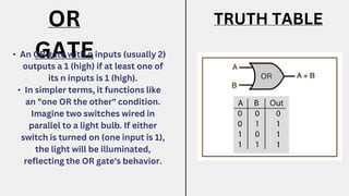
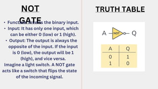
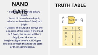
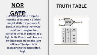
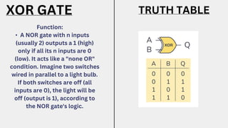
UNDERSTANDING
LOGIC GATES IN
DIGITAL CIRCUITS
Solving with tables
LOGIC
GATES
•
•
Exploring Logic Gates:
Types-
• AND GATE
• OR GATE
• NOT GATE
• NAND GATE
• NOR GATE
• XOR GATE
• XNOR GATE
Definition:
• An AND gate with n inputs
(usually 2) outputs a 1 (high)
only if all its n inputs are 1
(high).
• In simpler terms, it acts like a
"both AND" condition. Imagine
two switches connected in
series for a light to turn on.
The light will only turn on if
both switches are turned on
(both inputs are 1), mimicking
the AND gate's functionality.
AND GATE TRUTH TABLE
OR
GATE
• An OR gate with n inputs (usually 2)
outputs a 1 (high) if at least one of
its n inputs is 1 (high).
• In simpler terms, it functions like
an "one OR the other" condition.
Imagine two switches wired in
parallel to a light bulb. If either
switch is turned on (one input is 1),
the light will be illuminated,
reflecting the OR gate's behavior.
TRUTH TABLE
NOT
GATE
• Function: Inverts the binary input.
• Input: It has only one input, which
can be either 0 (low) or 1 (high).
• Output: The output is always the
opposite of the input. If the input
is 0 (low), the output will be 1
(high), and vice versa.
Imagine a light switch. A NOT gate
acts like a switch that flips the state
of the incoming signal.
TRUTH TABLE
NAND
GATE
• Function: Inverts the binary
input.
• Input: It has only one input,
which can be either 0 (low) or 1
(high).
• Output: The output is always the
opposite of the input. If the input
is 0 (low), the output will be 1
(high), and vice versa.
Imagine a light switch. A NOT gate
acts like a switch that flips the state
of the incoming signal.
TRUTH TABLE
NOR
GATE
Function:
• A NOR gate with n inputs
(usually 2) outputs a 1 (high)
only if all its n inputs are 0
(low). It acts like a "none OR"
condition. Imagine two
switches wired in parallel to a
light bulb. If both switches are
off (all inputs are 0), the light
will be off (output is 1),
according to the NOR gate's
logic.
TRUTH TABLE
XOR GATE
Function:
• A NOR gate with n inputs
(usually 2) outputs a 1 (high)
only if all its n inputs are 0
(low). It acts like a "none OR"
condition. Imagine two switches
wired in parallel to a light bulb.
If both switches are off (all
inputs are 0), the light will be
off (output is 1), according to
the NOR gate's logic.
TRUTH TABLE
XNOR GATE
Function:
• A NOR gate with n inputs
(usually 2) outputs a 1 (high)
only if all its n inputs are 0
(low). It acts like a "none OR"
condition. Imagine two
switches wired in parallel to a
light bulb. If both switches are
off (all inputs are 0), the light
will be off (output is 1),
according to the NOR gate's
logic.
TRUTH TABLE
KEY TAKEAWAYS AND
CONCLUSION
In essence, logic gates are the
fundamental building blocks that
enable digital circuits to process
information and make decisions
based on binary logic. Their
versatility and ability to be
combined in complex ways make
them essential for the vast array of
digital technologies we rely on
today.
Thank you for
diving into logic
gates!

LOGIC GATES, TYPES AND THEIR TRUTH TABLES.

  • 1.
    UNDERSTANDING LOGIC GATES IN DIGITALCIRCUITS Solving with tables
  • 2.
  • 3.
    Exploring Logic Gates: Types- •AND GATE • OR GATE • NOT GATE • NAND GATE • NOR GATE • XOR GATE • XNOR GATE
  • 4.
    Definition: • An ANDgate with n inputs (usually 2) outputs a 1 (high) only if all its n inputs are 1 (high). • In simpler terms, it acts like a "both AND" condition. Imagine two switches connected in series for a light to turn on. The light will only turn on if both switches are turned on (both inputs are 1), mimicking the AND gate's functionality. AND GATE TRUTH TABLE
  • 5.
    OR GATE • An ORgate with n inputs (usually 2) outputs a 1 (high) if at least one of its n inputs is 1 (high). • In simpler terms, it functions like an "one OR the other" condition. Imagine two switches wired in parallel to a light bulb. If either switch is turned on (one input is 1), the light will be illuminated, reflecting the OR gate's behavior. TRUTH TABLE
  • 6.
    NOT GATE • Function: Invertsthe binary input. • Input: It has only one input, which can be either 0 (low) or 1 (high). • Output: The output is always the opposite of the input. If the input is 0 (low), the output will be 1 (high), and vice versa. Imagine a light switch. A NOT gate acts like a switch that flips the state of the incoming signal. TRUTH TABLE
  • 7.
    NAND GATE • Function: Invertsthe binary input. • Input: It has only one input, which can be either 0 (low) or 1 (high). • Output: The output is always the opposite of the input. If the input is 0 (low), the output will be 1 (high), and vice versa. Imagine a light switch. A NOT gate acts like a switch that flips the state of the incoming signal. TRUTH TABLE
  • 8.
    NOR GATE Function: • A NORgate with n inputs (usually 2) outputs a 1 (high) only if all its n inputs are 0 (low). It acts like a "none OR" condition. Imagine two switches wired in parallel to a light bulb. If both switches are off (all inputs are 0), the light will be off (output is 1), according to the NOR gate's logic. TRUTH TABLE
  • 9.
    XOR GATE Function: • ANOR gate with n inputs (usually 2) outputs a 1 (high) only if all its n inputs are 0 (low). It acts like a "none OR" condition. Imagine two switches wired in parallel to a light bulb. If both switches are off (all inputs are 0), the light will be off (output is 1), according to the NOR gate's logic. TRUTH TABLE
  • 10.
    XNOR GATE Function: • ANOR gate with n inputs (usually 2) outputs a 1 (high) only if all its n inputs are 0 (low). It acts like a "none OR" condition. Imagine two switches wired in parallel to a light bulb. If both switches are off (all inputs are 0), the light will be off (output is 1), according to the NOR gate's logic. TRUTH TABLE
  • 11.
    KEY TAKEAWAYS AND CONCLUSION Inessence, logic gates are the fundamental building blocks that enable digital circuits to process information and make decisions based on binary logic. Their versatility and ability to be combined in complex ways make them essential for the vast array of digital technologies we rely on today.
  • 12.
    Thank you for divinginto logic gates!