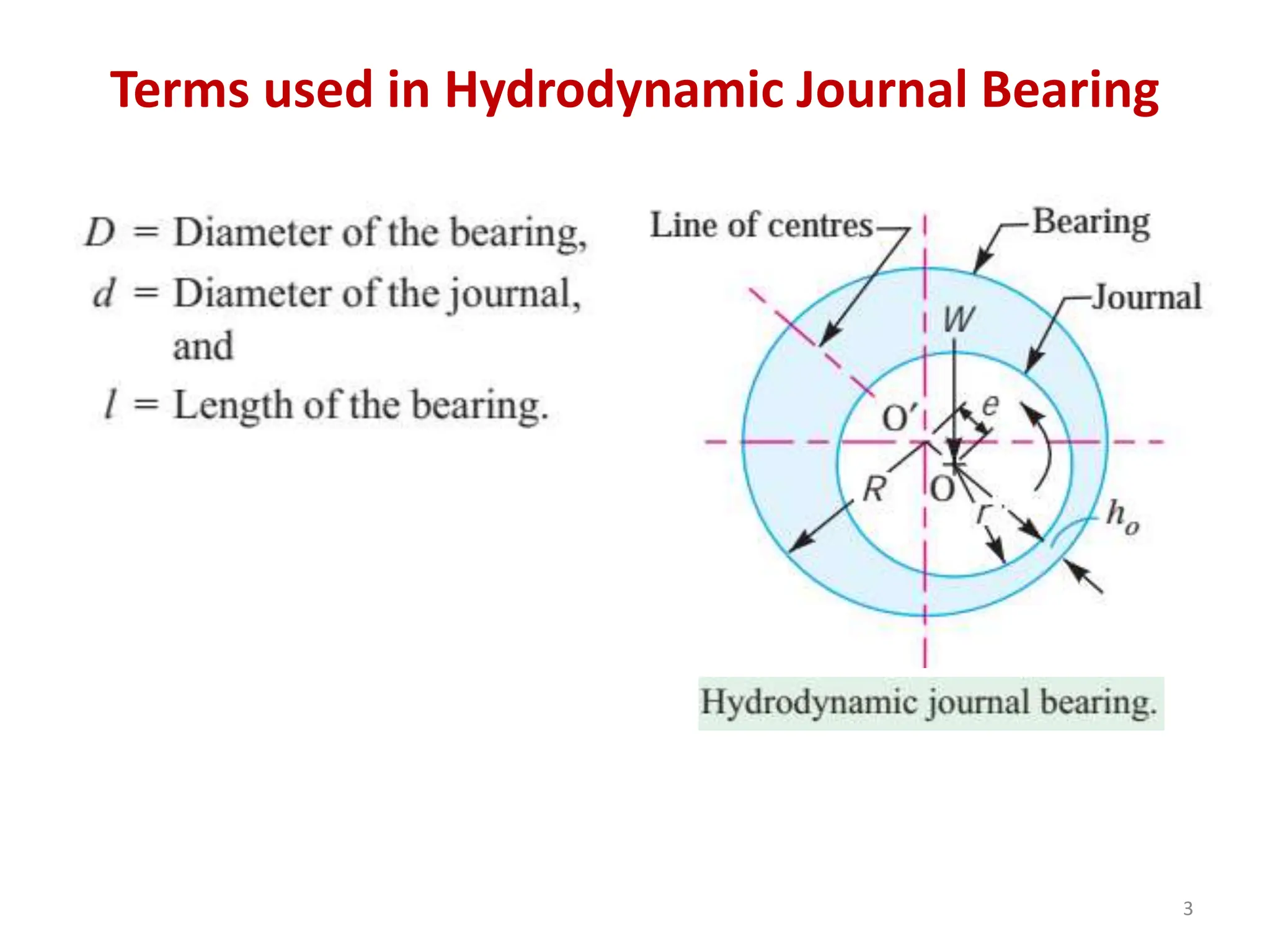
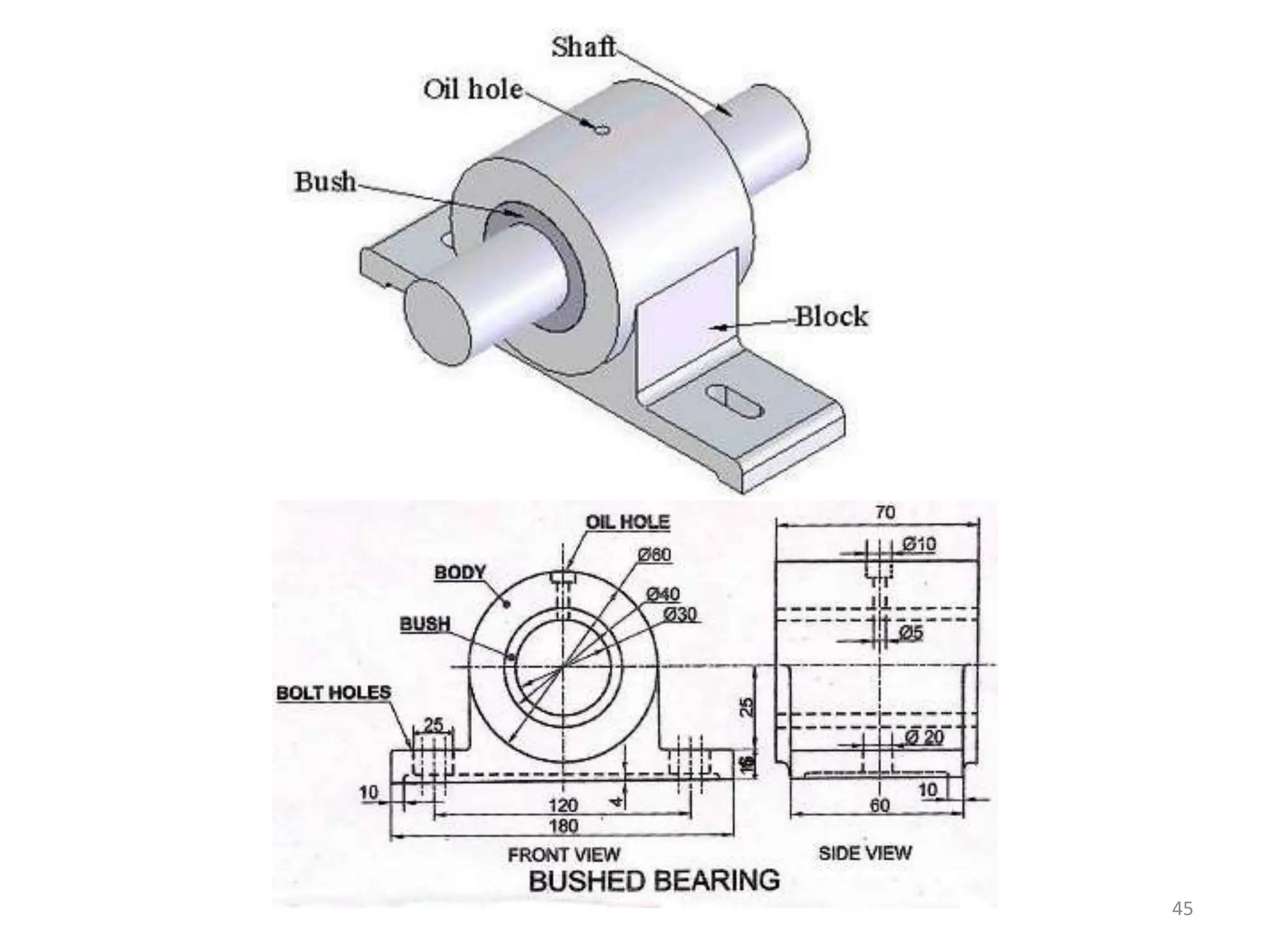
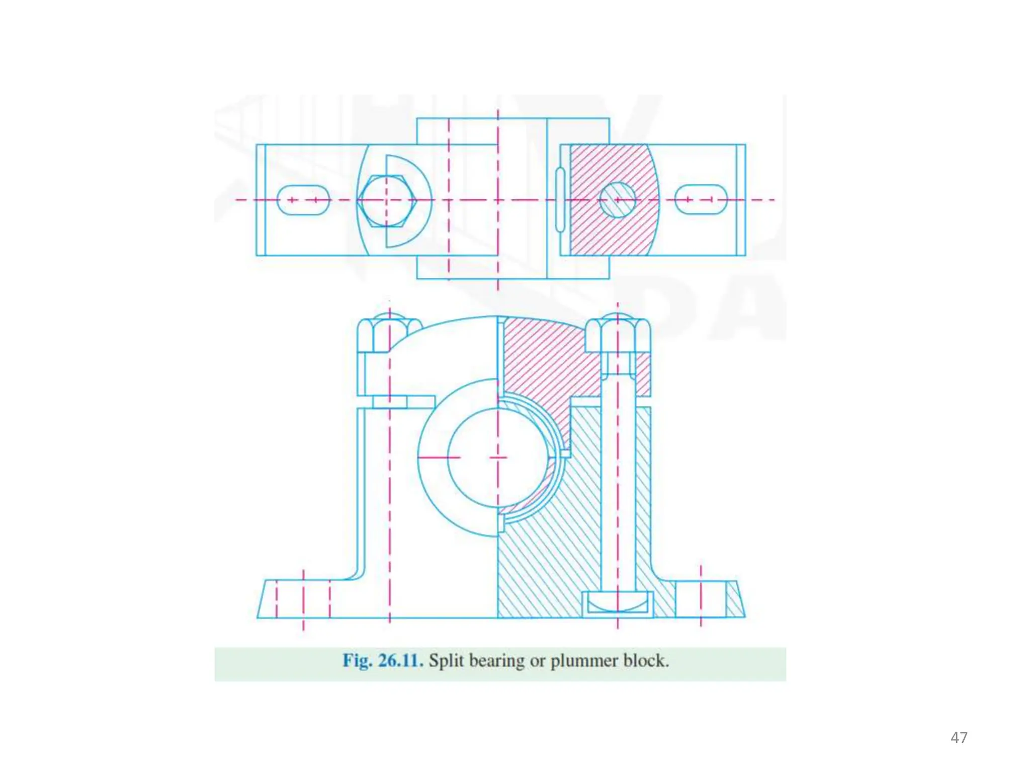
1
Machine Design – II
Code: ME- 311
Credit Hours: 3
Lecture
Sliding Contact Bearings
Dr. Muhammad Imran
Mechanical Engineering Program
University of Engineering & Technology Taxila
Terms used in Hydrodynamic Journal Bearing
3
• Diametral clearance. It the difference between
the diameters of the bearing and the journal.
c = D – d .
• Radial clearance. It is the difference between
the radii of the bearing and the journal.
Mathematically, radial clearance,
• Diametral clearance ratio. It is the ratio of the
diametral clearance to the diameter of the
journal.
4
• Eccentricity. It is the radial distance between the
centre (O) of the bearing and the displaced
centre (O′) of the bearing under load. It is
denoted by e.
• Minimum oil film thickness. It is the minimum
distance between the bearing and the journal,
under complete lubrication condition. It is
denoted by h0. Its value may be assumed as c/4.
• Attitude or eccentricity ratio. It is the ratio of
the eccentricity to the radial clearance.
5
• Short and long bearing.
If the ratio of the length to the diameter of the
journal (i.e. l/d) is less than 1, then the bearing is
said to be short bearing. On the other hand, if
l/d is greater than 1, then the bearing is known
as long bearing.
Note: When the length of the journal (l) is equal
to the diameter of the journal (d), then the
bearing is called square bearing.
6
Bearing Characteristic Number and Bearing
Modulus for Journal Bearings
• The coefficient of friction in design of bearings
is of great importance, because it affords a
means for determining the loss of power due
to bearing friction.
• It has been shown by experiments that the
coefficient of friction for a full lubricated
journal bearing is a function of three variables,
i.e.
•
7
The factor ZN/p is termed as bearing characteristic number
and is a dimensionless number. as obtained by McKee brothers
(S.A. McKee and T.R. McKee)
8
Minimum amount of friction
occurs at A and at this point the
value of ZN/p is known as
bearing modulus which is
denoted by K. The bearing
should not be operated at this
value, because decrease in
speed or increase in pressure
will break the oil film and make
the journal to operate with
metal to metal contact.
9
In order to prevent such conditions, the bearing should be designed for a value of
ZN / p at least three times the minimum value of bearing modulus (K). If the bearing
is subjected to large fluctuations of load and heavy impacts, the value of ZN / p = 15
K may be used.
Coefficient of Friction for Journal Bearings
10
Critical Pressure of the Journal Bearing
• The pressure at which the oil film breaks down
so that metal to metal contact begins, is
known as critical pressure or the minimum
operating pressure of the bearing. It may be
obtained by the following empirical relation,
11
Sommerfeld Number
• The Sommerfeld number is also a dimensionless
parameter used extensively in the design of journal
bearings.
12
Heat Generated in a Journal Bearing
• The heat generated in a bearing is due to the
fluid friction and friction of the parts having
relative motion.
13
14
15
The mass of the oil to remove the heat generated at the bearing may be
obtained by equating the heat generated to the heat taken away by the oil.
Mass of lubricating oil required for artificial cooling
Unit Conversion
DESIGN STEPS FOR HYDRODYNAMIC JOURNAL BEARING
1. Calculate the diameter of journal (d) from power, torque and stress
relationships such as
C / d = 0.001
Problem: 1
Problem: 2
Solid Journal Bearing
• A solid bearing is the simplest form of journal bearing.
• It is simply a block of cast iron with a hole for a shaft
providing running fit.
• The lower portion of the block is extended to form a base
plate with two holes to receive bolts for fastening it to
the frame. An oil hole is drilled at the top for lubrication.
The main disadvantages of this bearing are:
1. There is no provision for adjustment in case of wear,
2. The shaft must be passed into the bearing axially.
• This type of bearing is used when the shaft speed is not
very high and the shaft carries light loads.
42
43
Bushed Bearing
• A bushed bearing is an improved solid bearing in
which a bush of brass or gun metal is provided.
• The outside of the bush is a driving fit in the hole
of the casting whereas the inside is a running fit
for the shaft.
• When the bush gets worn out, it can be easily
replaced.
• In small bearings, the frictional force itself holds
the bush in position, but for shafts transmitting
high power, grub screws are used for the
prevention of rotation and sliding of the bush.
44
45
Split Bearing or Plummer Block
• A split-bearing is used for shafts running at
high speeds and carrying heavy loads.
• A split bearing consists of a cast iron base,
gunmetal or phosphor bronze brasses, bushes
or steps made in two-halves and a cast iron
cap.
• The two halves of the brasses are held
together by a cap or cover by means of steel
bolts and nuts.
46
47
48
49
Design of Bearing Caps and Bolts
When a split bearing is used, the bearing cap is tightened on the top. The load is
usually carried by the bearing and not the cap, but in some cases e.g. split
connecting rod ends in double acting steam engines, a considerable load comes
on the cap of the bearing. Therefore, the cap and the holding down bolts must
be designed for full load.
The cap is generally regarded as a simply supported beam, supported by holding down
bolts and loaded at the centre as shown in Fig.
50
Oil Groves
• The oil grooves are cut into the
plain bearing surfaces to assist in
the distribution of the oil
between the rubbing surfaces.
• It prevents squeezing of the oil
film from heavily loaded low
speed journals and bearings.
• The tendency to squeeze out oil is
greater in low speed than in high
speed bearings, because the oil
has greater wedging action at
high speeds.
51
52
Example 26.7. A wall bracket supports a plummer block for 80 mm diameter shaft. The
length of bearing is 120 mm. The cap of bearing is fastened by means of four bolts, two on
each side of the shaft. The cap is to withstand a load of 16.5 kN. The distance between the
centre lines of the bolts is 150 mm. Determine the thickness of the bearing cap and the
diameter of the bolts. Assume safe stresses in tension for the material of the cap, which is
cast iron, as 15 MPa and for bolts as 35 MPa. Also check the deflection of the bearing cap
taking E = 110 kN / mm2.
53
Thrust Bearings
• A thrust bearing is used to guide or support the shaft
which is subjected to a load along the axis of the shaft.
Such type of bearings are used in turbines and propeller
shafts.
• The thrust bearings are of the following two types :
1. Foot step/pivot bearings
2. Collar bearings
• In a foot step or pivot bearing, the loaded shaft is
vertical and the end of the shaft rests within the bearing.
• In case of collar bearing, the shaft continues through
the bearing (e.g. Center bearing of propeller shaft).
54
Footstep or Pivot Bearings
55
In design, it is assumed that the pressure is uniformly
distributed throughout the bearing surface.
Let
56
57
Collar Bearings
58
59
When the pressure is uniformly distributed over the bearing
surface, then bearing pressure,
60
61
Example 26.8. A footstep bearing supports a shaft of 150 mm diameter
which is counterbored at the end with a hole diameter of 50 mm. If the
bearing pressure is limited to 0.8 N/mm2 and the speed is 100 r.p.m.;
find : 1. The load to be supported; 2. The power lost in friction; and 3. The
heat generated at the bearing. Assume coefficient of friction = 0.015.
62
63
Example 26.10. The thrust of propeller shaft in a marine engine is taken up by a number
of collars integral with the shaft which is 300 mm is diameter. The thrust on the shaft is
200 kN and the speed is 75 r.p.m. Taking μ constant and equal to 0.05 and assuming the
bearing pressure as uniform and equal to 0.3 N/mm2,
find : 1. Number of collars required, 2. Power lost in friction, and 3. Heat generated at
the bearing in kJ/min.
64
65

Lecture 2 Sliding Contact Bearing.pptx

  • 1.
  • 2.
    Machine Design –II Code: ME- 311 Credit Hours: 3 Lecture Sliding Contact Bearings Dr. Muhammad Imran Mechanical Engineering Program University of Engineering & Technology Taxila
  • 3.
    Terms used inHydrodynamic Journal Bearing 3
  • 4.
    • Diametral clearance.It the difference between the diameters of the bearing and the journal. c = D – d . • Radial clearance. It is the difference between the radii of the bearing and the journal. Mathematically, radial clearance, • Diametral clearance ratio. It is the ratio of the diametral clearance to the diameter of the journal. 4
  • 5.
    • Eccentricity. Itis the radial distance between the centre (O) of the bearing and the displaced centre (O′) of the bearing under load. It is denoted by e. • Minimum oil film thickness. It is the minimum distance between the bearing and the journal, under complete lubrication condition. It is denoted by h0. Its value may be assumed as c/4. • Attitude or eccentricity ratio. It is the ratio of the eccentricity to the radial clearance. 5
  • 6.
    • Short andlong bearing. If the ratio of the length to the diameter of the journal (i.e. l/d) is less than 1, then the bearing is said to be short bearing. On the other hand, if l/d is greater than 1, then the bearing is known as long bearing. Note: When the length of the journal (l) is equal to the diameter of the journal (d), then the bearing is called square bearing. 6
  • 7.
    Bearing Characteristic Numberand Bearing Modulus for Journal Bearings • The coefficient of friction in design of bearings is of great importance, because it affords a means for determining the loss of power due to bearing friction. • It has been shown by experiments that the coefficient of friction for a full lubricated journal bearing is a function of three variables, i.e. • 7
  • 8.
    The factor ZN/pis termed as bearing characteristic number and is a dimensionless number. as obtained by McKee brothers (S.A. McKee and T.R. McKee) 8
  • 9.
    Minimum amount offriction occurs at A and at this point the value of ZN/p is known as bearing modulus which is denoted by K. The bearing should not be operated at this value, because decrease in speed or increase in pressure will break the oil film and make the journal to operate with metal to metal contact. 9 In order to prevent such conditions, the bearing should be designed for a value of ZN / p at least three times the minimum value of bearing modulus (K). If the bearing is subjected to large fluctuations of load and heavy impacts, the value of ZN / p = 15 K may be used.
  • 10.
    Coefficient of Frictionfor Journal Bearings 10
  • 11.
    Critical Pressure ofthe Journal Bearing • The pressure at which the oil film breaks down so that metal to metal contact begins, is known as critical pressure or the minimum operating pressure of the bearing. It may be obtained by the following empirical relation, 11
  • 12.
    Sommerfeld Number • TheSommerfeld number is also a dimensionless parameter used extensively in the design of journal bearings. 12
  • 13.
    Heat Generated ina Journal Bearing • The heat generated in a bearing is due to the fluid friction and friction of the parts having relative motion. 13
  • 14.
  • 15.
    15 The mass ofthe oil to remove the heat generated at the bearing may be obtained by equating the heat generated to the heat taken away by the oil. Mass of lubricating oil required for artificial cooling
  • 16.
  • 21.
    DESIGN STEPS FORHYDRODYNAMIC JOURNAL BEARING 1. Calculate the diameter of journal (d) from power, torque and stress relationships such as C / d = 0.001
  • 31.
  • 34.
  • 42.
    Solid Journal Bearing •A solid bearing is the simplest form of journal bearing. • It is simply a block of cast iron with a hole for a shaft providing running fit. • The lower portion of the block is extended to form a base plate with two holes to receive bolts for fastening it to the frame. An oil hole is drilled at the top for lubrication. The main disadvantages of this bearing are: 1. There is no provision for adjustment in case of wear, 2. The shaft must be passed into the bearing axially. • This type of bearing is used when the shaft speed is not very high and the shaft carries light loads. 42
  • 43.
  • 44.
    Bushed Bearing • Abushed bearing is an improved solid bearing in which a bush of brass or gun metal is provided. • The outside of the bush is a driving fit in the hole of the casting whereas the inside is a running fit for the shaft. • When the bush gets worn out, it can be easily replaced. • In small bearings, the frictional force itself holds the bush in position, but for shafts transmitting high power, grub screws are used for the prevention of rotation and sliding of the bush. 44
  • 45.
  • 46.
    Split Bearing orPlummer Block • A split-bearing is used for shafts running at high speeds and carrying heavy loads. • A split bearing consists of a cast iron base, gunmetal or phosphor bronze brasses, bushes or steps made in two-halves and a cast iron cap. • The two halves of the brasses are held together by a cap or cover by means of steel bolts and nuts. 46
  • 47.
  • 48.
  • 49.
    49 Design of BearingCaps and Bolts When a split bearing is used, the bearing cap is tightened on the top. The load is usually carried by the bearing and not the cap, but in some cases e.g. split connecting rod ends in double acting steam engines, a considerable load comes on the cap of the bearing. Therefore, the cap and the holding down bolts must be designed for full load. The cap is generally regarded as a simply supported beam, supported by holding down bolts and loaded at the centre as shown in Fig.
  • 50.
  • 51.
    Oil Groves • Theoil grooves are cut into the plain bearing surfaces to assist in the distribution of the oil between the rubbing surfaces. • It prevents squeezing of the oil film from heavily loaded low speed journals and bearings. • The tendency to squeeze out oil is greater in low speed than in high speed bearings, because the oil has greater wedging action at high speeds. 51
  • 52.
    52 Example 26.7. Awall bracket supports a plummer block for 80 mm diameter shaft. The length of bearing is 120 mm. The cap of bearing is fastened by means of four bolts, two on each side of the shaft. The cap is to withstand a load of 16.5 kN. The distance between the centre lines of the bolts is 150 mm. Determine the thickness of the bearing cap and the diameter of the bolts. Assume safe stresses in tension for the material of the cap, which is cast iron, as 15 MPa and for bolts as 35 MPa. Also check the deflection of the bearing cap taking E = 110 kN / mm2.
  • 53.
  • 54.
    Thrust Bearings • Athrust bearing is used to guide or support the shaft which is subjected to a load along the axis of the shaft. Such type of bearings are used in turbines and propeller shafts. • The thrust bearings are of the following two types : 1. Foot step/pivot bearings 2. Collar bearings • In a foot step or pivot bearing, the loaded shaft is vertical and the end of the shaft rests within the bearing. • In case of collar bearing, the shaft continues through the bearing (e.g. Center bearing of propeller shaft). 54
  • 55.
    Footstep or PivotBearings 55
  • 56.
    In design, itis assumed that the pressure is uniformly distributed throughout the bearing surface. Let 56
  • 57.
  • 58.
  • 59.
    59 When the pressureis uniformly distributed over the bearing surface, then bearing pressure,
  • 60.
  • 61.
    61 Example 26.8. Afootstep bearing supports a shaft of 150 mm diameter which is counterbored at the end with a hole diameter of 50 mm. If the bearing pressure is limited to 0.8 N/mm2 and the speed is 100 r.p.m.; find : 1. The load to be supported; 2. The power lost in friction; and 3. The heat generated at the bearing. Assume coefficient of friction = 0.015.
  • 62.
  • 63.
    63 Example 26.10. Thethrust of propeller shaft in a marine engine is taken up by a number of collars integral with the shaft which is 300 mm is diameter. The thrust on the shaft is 200 kN and the speed is 75 r.p.m. Taking μ constant and equal to 0.05 and assuming the bearing pressure as uniform and equal to 0.3 N/mm2, find : 1. Number of collars required, 2. Power lost in friction, and 3. Heat generated at the bearing in kJ/min.
  • 64.
  • 65.