
Recommended
Recommended
More Related Content
Similar to Bearings basics - Sliding contact 2023.pdf
Similar to Bearings basics - Sliding contact 2023.pdf (20)
Recently uploaded
Recently uploaded (20)
Bearings basics - Sliding contact 2023.pdf
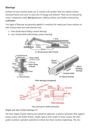
- 1. Bearings: Surfaces of some machine parts are in contact with another that has relative motion inducing friction and wear to cause loss of energy and material. These can be reduced by using a component called Bearing between rubbing surfaces and further enhanced by Lubrication. Two types of bearings are generally applied in machines for rotary and linear motions to take mainly radial and axial (thrust) load; 1. Plain/bush/sleeve/sliding contact bearings 2. Anti-friction/ball/roller/rolling contact bearings Plain bearings (conceptual) Plain bearing for shafts (schematic) Shapes and sizes of plain bearings <?> The basic shapes of plain bearing are cylindrical-spherical, or planar-prismatic that support rotary motion like shafts-frames, wheels-axles & ball-socket or linear motion like slide- guides & pistons-cylinders (cylindrical surfaces but linear motion) respectively. The size-
- 2. shape of actual contact area (patch) would depend upon the load and material (contact phenomena).which would change over time depending upon contact pressure and rubbing velocity<?>. Advantages of Plain Bearings (compared to anti-friction bearings) 1. Low initial cost 2. Simple shaft and housing design 3. Small dimension & lightweight 4. Low noise at high speed 5. Less sensitive to dust ingress 6. Less chance of fretting & fatigue <?> 7. Less subjected to <?> 8. Easy to replace Materials of construction Desirable properties of plain bearing materials along with low coefficient of friction*; <?> 1. High compressive strength and hardness (for load capacity and wear resistance) 2. Ductility & low hardness (for conformability and embeddability) 3. Fatigue strength (for cyclic loading) 4. Low shear strength (for smoothing surface asperities/improving surface roughness) 5. Low modulus of elasticity (for accommodating misalignment & deflection) 6. Good material compatibility (for low adhesive wear and seizure resistance) 7. High corrosion/oxidation resistance (for corrosion wear) 8. High thermal conductivity & less thermal expansion (for heat dissipation and clearance maintenance) 9. High porosity (for holding lubricant) 10. Low cost (availability, manufacturability, etc.) (*Contradicting requirements, how to fulfill!!? to be discussed in detail, next semester) ‘Sleeve/bush’ of cast iron, brass, bronze, Babbitt, white metal, graphite, plastics, ceramic, etc. even composites are used against hardened and ground journal/shaft of steel paired as bearing surfaces. ‘Strategic’ use of bearing materials for sleeve/bush along with lubrication enhances their performance. Sleeves for radial load of different materials and ‘modifications’
- 3. Lubrication** Drastic reduction in friction and wear is observed when bearing surfaces are applied with oil like liquid. The thickness of oil layer formed between bearing surface depends on several parameters but falls in three regimes; boundary, mixed, and hydrodynamic lubrication. Here only ‘boundary lubrication’ condition in which film of lubricant and asperity of bearing surfaces dominate the contact that may be useful in many applications for lighter loads, lower surface speed, infrequent usage etc. is considered for finding bearing dimensions. ‘Solid film lubrication’ is also possible in which graphite or molybdenum disulfide like dry lubricants or self-lubricating polymers, such as Teflon or nylon, are used as bearing material. **More on lubrication, next semester Boundary lubricated plain sleeve bearing Design Bearings of small machines for home-kitchen, office, toys, up to large-heavy construction- agricultural machinery are boundary-lubricated. Such bearings may be lubricated by hand/ gravity oilers, grease, oil-filled porous metal. Solid film lubricated bearings use graphite/ molybdenum disulfide-impregnation material, or self-lubricating polymers. Design of these bearings is largely an empirical process based on documented designer-user experience. Primary design parameters at the sliding interface are specific bearing pressure p (due to load), relative velocity v and operating temperature θ. Temperature of bearing may be calculated by equating heat generated at interface to heat dissipated to the surroundings in unit time (through all heat transfer modes). It would be quite difficult to find exact solution for wide verities of configurations and operating conditions. Simplifying, the heat balance equation takes the general form; Δθ = f (p·v) (geometry, material, friction coefficient) It can be seen that the p·v product dominates temperature rise, hence widely used as a design parameter for boundary-lubricated bearings. Operating values of p, v, and p·v must all be less than the limiting values shown in the table below. Design Limits for Boundary-Lubricated Bearings Operating in Contact with Steel Shafts Bearing Sleeve Material Max. Allowable Pressure, pmax Max. Allowable Sliding Velocity, vmax Max. Allowable Product (pv)max Approx. Max. Allowable Op. Temp.2 θmax ksi MPa ft/min m/min ksi-ft/min MPa-m/min °F °C Porous bronze 2.0 13.8 1200 365.8 50 105.1 450 232.2 Porous lead-bronze 0.8 5.5 1500 457.2 60 126.1 450 232.2 Porous iron 3.0 20.7 400 121.9 30 63.0 450 232.2 Porous bronze-iron 2.5 17.2 800 243.8 35 73.6 450 232.2 Porous lead-iron 1.0 6.9 800 243.8 50 105.1 450 232.2 Aluminum 2.0 13.8 1200 365.8 50 105.1 250 120.8 Phenolics 6.0 41.4 2500 762.0 15 31.5 200 93.2
- 4. Nylon 2.0 13.8 600 182.9 3 6.3 200 93.2 Teflon 0.5 3.5 50 15.2 1 2.1 500 259.9 Filled Teflon 2.5 17.2 1000 304.8 10 21.0 500 259.9 Teflon fabric 60.0 413.7 150 45.7 25 52.5 500 259.9 Polycarbonate 1.0 6.9 1000 304.8 3 6.3 220 104.3 Acetal 2.0 13.8 600 182.9 3 6.3 200 93.2 Carbon-Graphite 0.6 4.1 2500 762.0 15 31.5 750 398.8 Rubber 0.05 0.34 4000 1219.2 — — 150 65.4 Wood 2.0 13.8 2000 609.6 12 25.2 160 71 2If lubricant breakdown temperature is lower; it should be used as limiting temperature. The parameters p, v, and pv may be calculated as follows; p = radial load/projected area = P/dl N/mm2 vcont = continuous sliding velocity of journal = π·d·N/60 mm/s vosc = average oscillatory sliding velocity of journal = π·d·φ·f/(60x2π) = d·φ·f/120 mm/s. and pv = p x v MPa-m/s Where, P = total radial bearing load, N d = journal diameter, mm l = sleeve length, mm N = journal speed (relative to sleeve), rpm φ = total angle swept for each oscillation, rad f = frequency of oscillation, osc/min Possible preliminary design procedure for boundary lubricated plain bearing: 1. If not given, calculate journal (shaft) diameter d with strength equations <?> 2. Find effective radial bearing load P 3. Select general sleeve materials 4. Calculate v. if v > vmax of the table. If v > vmax, redesign 5. Find limiting value (pv)max for the bearing material from above table 6. Calculate p by using results of 4 and 5. If p > pmax from the table, redesign 7. Using result of step 6, and known values of P and d, calculate l 8. It is found that successful bearings have length/diameter ratios within 0.5 ≤ l/d ≤ 2. So, design completes if result of 7 falls within it. If not, may be redesigned. Boundary lubricated plain thrust bearings design Because plane of bearing surfaces are transverse, thrust bearing’s pv makes two operating conditions with ‘dry friction’ i.e. without any lubrication; 1. Uniform pressure, for ‘new condition’, in which p is same (p = C) on every point while v varies along radius (v r) making pv variable causing faster wear at larger radii. 2. Uniform wear, after initial wear, the profile of surface changes in such a way that pv becomes constant (pv = C), hence all the surface wears at same rate. <?> 3 3 2 2 2 2 4 ( ) ( ) Bearing pressure ; Frictional torque for uniform pressure and for uniform wear ( ) 3( ) 4 P P D d P D d p T T D d D d − + = = = − − <?>
- 5. The bearing area may be increased by making shaft end flanged, conical, adding one or more collars, or a shoulder as shown in figure above. Thrust washers are more common and may be used with sleeve or bushing to take radial load also. Several materials are used and some modification like radial or spiral groove is cut. <?> Although the equations mentioned earlier can be used for finding size of the bearing surface, here ‘preliminary design’ will be analogically same as of radial bearing with required changes. The parameters p, v, and pv may be calculated as follows; p = axial load/effective area = 2 2 4 ( ) P p D d = − N/mm2 vcont = continuous sliding velocity of collar at largest radius = π·D·N/60 mm/s vosc = average oscillatory sliding velocity of collar = π·D·ψ·f/60x2π) = D·ψ·f/120 mm/s and pv = p x v MPa-m/s Where, P = total radial bearing load, N D = collar diameter, mm l = sleeve length, mm N = collar speed (relative to washer), rpm ψ = total angle of oscillation, rad f = frequency of oscillation, osc/min Washers for axial load/thrust of different materials Preliminary Design of a Boundary-Lubricated Plain Bearing (Radial) - Numerical For a 20 mm diameter journal of a shaft rotating at 150 rpm is estimated to take pure radial load of 16 kN. Hot rolled carbon steel for shaft and a porous metal sleeve impregnated with oil is chosen for their characteristic low cost and low maintenance. Find desirable bearing length from preliminary analysis and suggest modification required. Take pmax = 13.8 MPa, vmax = 365.8 m/min, and pvmax = 105.1 MPa·m/min
- 6. Solution: (i) Schematic/sketch with input data; d = 20 mm N = 150 rpm P = 16 kN (ii) Sliding velocity vcont = πdN = π (0.020)(150) = 9.4 << 365.8 m/min ok pmax = pvmax/vcont = 105.1/9.4 = 11.1 MPa < 13.8 MPa, hence acceptable (iii) Bearing length l = P/pd = 16000/(11.1x106 x 0.020) = 0.072 m → 72 mm → l/d = 3.6 > 2.2 so make it 2 keeping l = 72 mm → d = 36 mm <?> With this d, values of p = 6.2 MPa, vcont = 15.1 m/min, and pv = 93.6 MPa·m/min (iv) Comments; But arrived bearing diameter for ‘good bearing’ may not be implemented without looking at the overall geometry of shaft and its considerations.. <?> Preliminary Design of a Boundary-Lubricated Plain Thrust Bearing - Numerical Find collar or washer size of same material to take axial load of 6000 N for above shaft. Solution: (can be solved in different way but simpler method is used as in sleeve) (i) Schematic sketch (ii) Selection of material, important values as given in data (iii) First estimate of D = 2d = 40 mm (or from catalog) Sliding velocity, vcont = πDN = π (0.04)(150) = 18.8 << 365.8 m/min, ok pmax = pvmax/vcont = 105.1/18.8 = 5.55 MPa < 13.8 MPa, acceptable (iv) Verifying D 2 2 2 2 4 4 6000 6.4 MPa ( ) (40 20 ) P p D d = = = − − < 13.8 MPa, safe (v) Comments: Larger washer will occupy more space while smaller may not match the sizes offered by manufacturer. So actually after selecting ‘preferred’ or new material, supplier, and catalog; washer may be selected and according collar dimensions < how about thickness of collar?> may be decided. Summary Questions: 1. What are plain bearings, their types, and applications? 2. List the desired properties of plain bearing materials with reasoning. 3. ….