
Recommended
More Related Content
What's hot
What's hot (20)
Similar to Lect18
Similar to Lect18 (20)
More from DrASSayyad
Recently uploaded
Recently uploaded (20)
Lect18
- 1. Dr. A. S. Sayyad Professor & Head Department of Structural Engineering Sanjivani College of Engineering, Kopargaon 423603. (An Autonomous Institute, Affiliated to Savitribai Phule Pune University, Pune) Finite Element Method In Civil Engineering Introduction to 3D elements
- 2. Introduction to 3D elements A three dimensional elements can be considered in the problems where field variables are dependent of x, y, & z. An example of a 3D Solid structure under loading is as shown in figure. 3D Solid under loading 3-D elements can actually be used to model all kinds of structural components including trusses, beams, plates, shells and so on. Typically 3-D solid elements can be tetrahedron or hexahedron in shape with either flat or curves surfaces. Applications 3D Elements: Three-dimensional analysis, analysis of axisymmetric solids.
- 3. 3D elements There are two basic families of three-dimensional elements similar to two- dimensional case. Extension of triangular elements will produce tetrahedrons in three dimensions. Similarly, rectangular parallelepipeds are generated on the extension of rectangular elements. Following are few commonly used 3D solid elements for finite element analysis. Tetrahedron Parallelepiped
- 4. 3D Tetrahedron element The simplest element of the tetrahedral family is 4 nodded tetrahedron. DOF per node: 03 (u, v, w), Total DOF: 12 04 DOF in x-direction (u1 u2 u3); 04 DOF in y- direction (v1 v2 v3); 04 DOF in z-direction (w1 w2 w3). Displacement Function: 1 2 3 4 5 6 7 8 9 10 11 12 u x y z v x y z w x y z
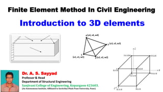
- 5. 3D Brick element (Hexahedron) The simplest element of the tetrahedral family is 4 nodded tetrahedron. Displacement Function: Figure shows, 8 nodded brick/hexahedron element in natural coordinate system. Displacement Function: DOF per node: 03 (u, v, w), Total DOF: 24 08 DOF in x-direction (u1 u2 u3); 08 DOF in y-direction (v1 v2 v3); 08 DOF in z-direction (w1 w2 w3). 1 2 3 4 5 6 7 8 u x y z xy yz xz xyz