Objectives
Be familiarwith fundamental concepts of electricity
Be able to recognise electrical hazards
Understand the Level 3 Field Operations Electrical
Safety Procedure
Understand your limitations
Know how to do your job safely so as to minimise the
risks
BACKGROUND
It isthe policy of BHI to conduct business
activities in a manner that does not harm people.
Every person has a responsibility to perform their
job in a safe manner.
Electrocutions rank 5th in work related fatalities
(5%, based on 1996 data) about half involve low
voltage, below 600 volts.
Centrilift has not had a fatality but we have had 4
to 6 serious electrical accidents/year.
6.
YOUR Responsibilities
Youare responsible for the health & safety of
_______ and those around you.
You must become familiar with the requirements
of the Field Ops. Electrical Safety Procedure.
You must ______ your supervisor if you
encounter a task that is beyond your
competence.
You must inspect, use & take appropriate care of
your assigned electrical & safety equipment.
You are empowered to __________ activities
when uncontrolled hazards are encountered.
yourself
discontinue
notify
7.
RESPONSIBILITIES
Operation/Area Manager
Implementation of the Level 3 Procedure
Ensure F.S. Personnel are trained and competent
Provide all required equipment (tools & test equipment)
Supervisor
Implementation of the Level 3 Procedure
Provide training and assess competency of personnel
Assign the work as outlined in the Electrical Competency Matrix (ECM)
Issue PPE
Field Service Personnel
Adhere to the Level 3 Procedure
Understand your limitations
Utilize approved PPE & Tools
8.
Water Analogy
One wayto describe how electricity works is to compare it with
water, since they both share common traits.
Water under pressure moves at a rate of flow that depends on the
resistance caused by the water pipes.
Basic Principles of Electricity
9.
Electricity acts inmuch the same way.
Pressure = Voltage (volts)
Flow = Current (amps)
Restriction of pipe = resistance (ohms)
Voltage, which is electrical pressure, moves
electrical current, or amperage, at a rate of flow
that depends on the "impedance" or electrical
resistance caused by the wires or other electrical
pathways.
Basic Principles of Electricity
10.
As with water,the exact relationship between pressure, flow and
resistance can be calculated mathematically using a formula
known as "Ohm's Law.“
It looks like this:
V = I x R
V = VOLTAGE (electrical pressure in Volts).
I = CURRENT (Amperes or Amps)
R = RESISTANCE (Ohms)
Basic Principles of Electricity
11.
Conductors and Insulators
Electricityflows easily through some materials and is blocked by
others.
Insulators have a very high resistance to the flow of
electricity and are used to cover wiring and other electrical
components.
Conductors have low resistance to electricity and are used for
wires, switches and electrical connections.
pics of insulator & conductor
Insulators such as glass, mica, rubber, or plastic used to
coat metals and other conductors help stop or reduce the
flow of electrical current.
Basic Principles of Electricity
12.
Electrical Potential
Themagnitude of current flowing from an energy source is the source's
electrical potential. Only when two unequal potentials are connected
by a conductor is a circuit created.
Circuit direction is affected by the universal law which says that
electricity always flows from a higher to a lower voltage potential.
Electricity may take multiple paths and it will flow through all possible
circuits, but the greatest amount of current will flow through the path of
least resistance. This is a key point in electrical safety since the human
body is made up of water, chemicals and materials that make it an
excellent conductor.
Diagram/drawing
Basic Principles of Electricity
13.
Bridging thegap between two different voltage levels with any
part of your body results in an electrical shock.
Electrical shock is the magnitude of current flow that passes
through you when you are situated in an electrical circuit.
Basic Principles of Electricity
14.
Grounding
One of themost important and least understood points in
electrical safety is the use of grounds and other circuit
protection devices.
Grounding is the act of providing a previously determined safe
path for stray electrical currents.
A properly installed ground offers a low resistance channel of
electricity to the ground. The most familiar type of ground is a
lighting rod. It attracts dangerous electrical energy and
conducts it harmlessly to the ground.
Basic Principles of Electricity
picture
15.
Since 95% ofall ground faults are caused by
malfunctions of equipment and electrical systems, tool
casings, machine enclosures and other conductive
materials that surround electrical lines must be safely
grounded. Double casings and properly installed
grounding connections help keep stray current and
electrical leakage from passing through any part of your
body.
Pic/diagram
Basic Principles of Electricity
16.
System grounding protectselectrical components
within the circuit from damage by excess voltage or
line surges.
Bypassing grounds or careless handling of
connections can result in electrical fires and other
accidents that may be fatal.
Basic Principles of Electricity
17.
Influential Variables. Theeffects of electric current
on the human body can vary depending on the
following:
Source characteristics (current, frequency, and
voltage of all electric energy sources).
Body impedance and the current's pathway through
the body.
How environmental conditions affect the body's
contact resistance.
Duration of the contact.
18.
5 Primary Hazardsof Electricity
1. Shock
Direct Hazard
Indirect Hazard
2. Burns
3. Arc-Blast
Thermal Radiation
Pressure Wave
Projectiles
4. Explosions
5. Fires
The effects of electric current on the human body can vary depending on the following:
Source characteristics (current, frequency, and voltage of all electric energy sources).
Body impedance and the current's pathway through the body.
How environmental conditions affect the body's contact resistance.
Duration of the contact.
19.
5 Primary Hazardsof Electricity (Cont.)
Electric Shock
Electric shock occurs when the body becomes part of a
path through which electricity can flow (i. e., the circuit).
The resulting effect on the body can be either direct or
indirect:
Direct. Injury or death can occur whenever electric current
flows through the human body. Currents of less than 30
milliamps (mA) can result in death.
Indirect. Although the electric current through the human
body may be well below the values required to cause
noticeable injury, human reaction can result in falls from
ladders or scaffolds, or movement into operating machinery.
Such reaction can result in serious injury or death.
graphic
20.
5 Primary Hazardsof Electricity
Electricity flowing
through the human
body can shock,
cause involuntary
muscle reaction,
paralyze muscles,
burn tissues and
organs, or kill. The
typical effects of
various electric
currents flowing
through the body on
the average 150-lb
male and 115-lb
female body are
given in the table.
21.
5 Primary Hazardsof Electricity
Electric Shock (Continued)
Delayed Effects. Damage to internal tissues may not be
apparent immediately after contact with the current. Internal
tissue swelling and edema are also possible.
Critical Path. The critical path of electricity through the body
is through the chest cavity. At levels noted in Table B-1, current
flowing from one hand to the other, from a hand to the opposite
foot, or from the head to either foot will pass through the chest
cavity paralyzing the respiratory or heart muscles, initiating
ventricular fibrillation and/or burning vital organs.
Biological Effects of Electrical Hazards
.
22.
5 Primary Hazardsof Electricity
Electric Shock (Continued)
Life-Threatening Effects. Charles F. Dalziel, "The Effects of Electric Shock on Man," , Ralph H.
Lee "Human Electrical Sheet" , and others have established the following criteria for the lethal
effects of electric shock:
Currents in excess of a human's "let-go" current (>16 mA at 60 Hz) passing through the chest can
produce collapse, unconsciousness, asphyxia, and even death.
Currents (>30 mA at 60 Hz) flowing through the nerve centers that control breathing can produce
respiratory inhibition, which could last long after interruption of the current.
Cardiac arrest can be caused by a current greater than or equal to 1 A at 60 Hz flowing in the
region of the heart.
Relatively high currents (0.25-1 A) can produce fatal damage to the central nervous system.
Currents greater than 5 A can produce deep body and organ burns, substantially raise body
temperature, and cause immediate death.
Delayed reactions and even death can be caused by serious burns or other complications.
The most dangerous current flow via the chest cavity is through the heart when the shock occurs
in the time relative to the normal heart rhythm. This current may cause ventricular fibrillation,
which is defined as repeated, rapid, uncoordinated contractions of the heart ventricles.
Ventricular fibrillation that alters the heart's normal rhythmic pumping action can be initiated by a
current flow of 75 mA or greater for 5 seconds (5-s) or more through the chest cavity.
23.
5 Primary Hazardsof Electricity
Burns
Although a current may not pass
through vital organs or nerve centers,
internal electrical burns can still occur.
These burns, which are a result of
heat generated by current flowing in
tissues, can be either at the skin
surface or in deeper layers (muscles,
bones, etc.), or both. Typically, tissues
damaged from this type of electrical
burn heal slowly.
Burns caused by electricity may be of
three types: electrical burns, arc
burns, and thermal contact burns.
24.
5 Primary Hazardsof Electricity
Arc-Blast
Burns caused by electric arcs are
similar to burns from high-
temperature sources. The
temperature of an electric arc, which
is in the range of 4,000-35,000°F,
can melt all known materials,
vaporize metal in close proximity,
and burn flesh and ignite clothing at
distances up to 10 ft from the arc.
Arc-blasts occur when powerful,
high-amperage currents arc through
the air. Arcing is the luminous
electrical discharge that occurs
when high voltages exist across a
gap between conductors and current
travels through the air.
25.
5 Primary Hazardsof Electricity
Arc-Blast
There are three primary hazards associated with an arc-blast.
Thermal Radiation. In most cases, the radiated thermal energy is only part of the total
energy available from the arc. Numerous factors, including skin color, area of skin
exposed, type of clothing have an effect on degree of injury. Proper clothing, work
distances, and overcurrent protection can improve the chances of curable burns.
Pressure Wave. A high- energy arcing fault can produce a considerable pressure wave.
Research has shown that a person 2 feet away from a 25,000 amp arc would experience
a force of approximately 480 pounds on the front of their body. In addition, such a
pressure wave can cause serious ear damage and memory loss due to mild
concussions. In some instances, the pressure wave may propel the victim away from the
arc- blast, reducing the exposure to the thermal energy. However, such rapid movement
could also cause serious physical injury.
Projectiles. The pressure wave can propel relatively large objects over a considerable
distance. In some cases, the pressure wave has sufficient force to snap the heads of 3/
8- inch steel bolts and knock over ordinary construction walls.
The high- energy arc also causes many of the copper and aluminum components in the
electrical equipment to become molten. These "droplets" of molten metal can be
propelled great distances by the pressure wave. Although these droplets cool rapidly,
they can still be above temperatures capable of causing serious burns or igniting
ordinary clothing at distances of 10 feet or more. In many cases, the burning effect is
much worse than the injury from shrapnel effects of the droplets.
26.
5 Primary Hazardsof Electricity
Explosions
Explosions occur when electricity provides a source of ignition
for an explosive mixture in the atmosphere. Explosive
atmospheres can result from the accumulation of flammable
vapors or gases generated by nearby sources and processes.
Ignition can be due to overheated conductors or equipment, or
normal arcing (sparking) at switch contacts
animated pic
27.
5 Primary Hazardsof Electricity
Fires
Electricity is one of the most common causes of fire both in the
home and workplace. Defective or misused electrical equipment
is a major cause, with high resistance connections being one of
the primary sources of ignition. High resistance connections
occur where wires are improperly spliced or connected to other
components such as receptacle outlets and switches.
Shauna - pic
28.
DEFINITIONS
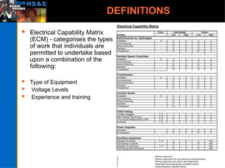
Electrical CapabilityMatrix
(ECM) - categorises the types
of work that individuals are
permitted to undertake based
upon a combination of the
following:
Type of Equipment
Voltage Levels
Experience and training
Electrical Capability Matrix
Entry
Voltages Low High Low High
Switchboards inc. Switchgear
Installation S U S U U
Commissioning - U* S U* A
Decommissioning - U* S U* A
Operation - U S U U
Troubleshoot - U* S U* A
Variable Speed Controllers
Installation S U S U U
Commissioning - U* S U* A
Decommissioning - U* S U* A
Operation - U* S U* U
Troubleshoot - U* S U* A
Transformers
Installation S U S U U
Commissioning - U* S U* A
Decommissioning - U* S U* A
Operation - U* S U* U
Troubleshoot - U* S U* A
Junction boxes
Installation S U S U U
Commissioning - U* S U* A
Decommissioning - U* S U* A
Operation - U* S U* U
Troubleshoot - U* S U* A
Cable testing
Insulation (Megger) T, S U S U U
High Potential Test (Hi-pot) T, S U S U U
Time Domain Reflectometry (TDR) T, S U S U U
Continuity T, S U S U U
Power Supplies
Energised - U* S U* A
De-energised - U* S U* A
Auxilliary equipment
Operation of spooler T, S U S U N/A
Fault finding on spooler - U* S U* N/A
Operation of workshack T, S U S U N/A
Fault finding within workshack - U* S U* N/A
U Without supervison
U* Without supervison but may require an accompaniment
A Without supervison but with an accompaniment
S Supervised by an appropriate competent person
T Unaccompanied if certified trained
Senior
Intermediate
29.
DEFINITIONS
ENTRY LEVEL –
No live work and not permitted to repair, maintain or fault
find on electrical equipment
Personnel assigned to this level would not normally have
previous training or experience with electrical equipment
Given specific training you will be authorized in the use of
high voltage / low power test equipment (i.e., megger/Hi-
pot)
30.
DEFINITIONS
INTERMEDIATE LEVEL –
Personnel who have had experience and training on low
voltage electrical power systems
Personnel assigned to this level are authorized to work on
live low voltage systems (below 600V)
31.
DEFINITIONS
SENIOR LEVEL –
Will have as a minimum the training & experience
required for that of the Intermediate Level, and in
addition:
Relevant training/experience of working on high voltage power
systems
This person may also assess competency for Entry &
Intermediate Levels
• Working on power systems exceeding 6kV may only
occur under exceptional circumstances and requires
written authorization from the relevant manager
32.
DEFINITIONS
Diagram tonegate the need for written definitions
Electrical System – A system which is, or may be,
connected to a source of electrical energy.
Electrical Equipment – Equipment that uses,
generates or contains electrical energy
Electrical Isolation – Secure disconnection and
separation of electrical equipment from every source
of electrical energy.
Energized (Live) – Electrical conductors, buses,
terminals or components which are connected to a
source of electrical energy.
33.
DEFINITIONS
De-Energized (Dead)– Free from any electrical connection
to a source of electrical charge.
Earthed (Grounded) – Connected to the general mass of earth
34.
DEFINITIONS
Lock Outand Tag Out (LOTO) – The placement of a safety lock and
employee danger tag on an energy isolating device in the safe position
indicating the energy isolating device shall not be operated or moved until
the lock and tag have been cleared
Competency - Personnel shall have sufficient technical knowledge and
experience to carry out work in a safe and efficient manner
35.
DEFINITIONS
Accompaniment –A additional person who is present at the work location
to provide any emergency response that may be required when the pre-job
electrical safety checklist indicates a requirement for accompaniment.
Instructed how to isolate power
How to notify/summon emergency response personnel
Administer First Aid/CPR if properly trained
36.
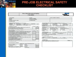
PRE-JOB ELECTRICAL
SAFETY CHECKLIST
ThePre-Job Electrical Safety Check List is
completed prior to the commencement of
the job. It identifies the hazards and the
control measures to be adopted to reduce or
eliminate the hazards.
The check list may be completed by the
supervisor or by the person carrying out the
work. In either case, the person completing
the check list must have current knowledge
of the work site and experience in assessing
the hazards.
Safe Working Practices
Are you qualified and trained to carry out the work?
Plan every Job
Use the correct tools for the job
Ensure tools have been maintained and power leads have been
installed in a safe manner
Report faulty tools /equipment to your supervisor
Be aware of the “switch off” points for tools and equipment under
use
Use appropriate personnel protective equipment
Use tools rated at 110 volts and below. In damp areas use extra
low voltage equipment/tools (50 volts and below)
Understand tools/equipment rating plates. Do not overload
equipment
Is work being carried out in a classified area?
40.
Precautions Against ElectricalHazards
Use only tools and equipment rated for the job
It is recommended to use a Residual Current Device (RCD) /
Ground Fault Circuit Interrupter (GFCI) when supplying portable
electrical tools/extension cords
Do not overload equipment
Understand the rating plates on tools and equipment – need pic of
plate and use as example to describe how to read it
If you suspect that a person has come into contact with electricity,
isolate the power supply before touching the victim. Alternatively
remove victim from source of supply using insulated material
Return suspect or faulty equipment for full inspection and repair
Carry out a visual inspection on cable/plugs /sockets etc. Look for
signs of wear and/or deterioration in cable systems
41.
Deciding to Workon Live Systems
Our normal procedure is to work on isolated &/or
de-energized systems
In general, working on or near live systems is not
normally permitted unless:
The voltage is less than 50 Volts (ELV)
It is unreasonable to work dead, and suitable
precautions are taken to prevent injury
Live working may only proceed if all hazards have
been identified and control measures implemented
to manage the risk
Precautions for WorkingDead
Isolate all sources of electrical energy including sources
of stored energy (capacitors etc)
Confirm the removal of the energy with a voltage
indicator
On High Voltage Systems use the grounding/earth stick
to ensure system is and remains discharged
Implement Lock Out/Tag Out procedure
….only after confirmation of the above may work
commence
44.
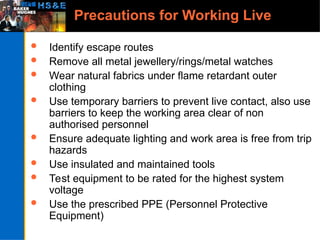
Precautions for WorkingLive
Identify escape routes
Remove all metal jewellery/rings/metal watches
Wear natural fabrics under flame retardant outer
clothing
Use temporary barriers to prevent live contact, also use
barriers to keep the working area clear of non
authorised personnel
Ensure adequate lighting and work area is free from trip
hazards
Use insulated and maintained tools
Test equipment to be rated for the highest system
voltage
Use the prescribed PPE (Personnel Protective
Equipment)
45.
Safe Working Distances
NominalVoltage Minimum Clear Distance (ft)
To Ground Condition 1 Condition 2 Condition 3
601 – 2500 V 3 4 5
2501 – 9000 V 4 5 6
9001 – 25,000 V 5 6 9
Condition 1 – Exposed live parts on one side and no live or grounded parts on the
other side of the working space, or exposed live parts on both sides effectively
guarded by suitable wood or insulating materials. Insulated wire or insulated bus
bars operating at not over 300 volts shall not be considered live parts.
Condition 2 – Exposed live parts on one side and grounded parts on the other
side. Concrete, brick or tile walls will be considered as grounded surfaces.
Condition 3 – Exposed live parts on both sides of the workspace (not guarded as
provided in condition 1) with the operator between.
Nominal Voltage Between Phases Elevation
601v – 7500V 8 ft 6 in.
7501 – 35,000V 9ft
Elevation of Unguarded Live
Parts Above Working Space
46.
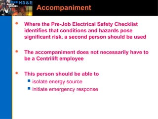
Accompaniment
Where thePre-Job Electrical Safety Checklist
identifies that conditions and hazards pose
significant risk, a second person should be used
The accompaniment does not necessarily have to
be a Centrilift employee
This person should be able to
isolate energy source
initiate emergency response
47.
Working in HazardousAreas
All areas where explosive
atmospheres can occur or
are considered hazardous
areas, are divided into
zones according to the
probability of the presence
of an explosive atmosphere.
The correct selection of
suitable tools and test
equipment must consider
the zone requirements and
the use of approved
equipment within the
particular zone. It is also
important that testing
carried out within
hazardous areas does not
give rise to an ignition
source e.g. cable insulation
testing with spark
generating tools such as a
megger.
Insert pic of guy working
With megger in gas cloud
area
Flammable gas
alwa
ys
prese
nt
>1000 hrs/year
Flammable gas
nor
mall
y
prese
nt
10-
1000
hrs/y
ear
Flammable gas not
normally
present
< 10 hrs/year
CENELEC/
IEC
Zone 0
(Zone 20 dust)
Zone 1
(Zone 21 dust)
Zone 2
(Zone 22 dust)
US - NEC 505 Zone 0 Zone 1 Zone 2
US - NEC 500 Division 1 Division 1 Division 2
48.
Personal Protective Equipment
Minimumstandard:
Flame retardant long sleeve clothing
Non Conductive hard hat
Safety glasses
Protective footwear (steel toe caps must be covered)
Additional PPE as required:
Face Visor
Insulating covers/mats to provide protection against
direct contact
Hot Gloves
Wear natural fabrics under flame retardant outer
clothing (best practice)
49.
Tools & TestEquipment
Multi-meters should not be used for proving circuits
dead on power systems.
Multi-meters must have fused leads
Voltage Indicators with fused leads are used on low and
high voltage power systems to confirm the presence of
electricity
A Proving Unit or known low power voltage source
shall be used to verify the correct operation of the
indicator before and after use.
Grounding/earthing stick to be used on High Voltage
Systems to ensure systems are satisfactorily
discharged
50.
Equipment Type PurposeCalibration Other Related Information
Voltage/Current Meters Meters used to measure voltage and current levels in electrical
circuitry.
Digital / analogue multi-meters should not be used for proving
power circuits dead.
Annual Shall be correctly rated for the
system voltage to be measured.
Voltage meters shall have insulated
probes and fused leads.
Voltage Indicator A device with fuse leads used to detect the absence of voltage on
HV and LV power systems after isolation
Annual A proving unit or known voltage
source will be used to verify
the correct operation of the
indicator before and after use.
Proving Unit A known low power voltage device used for checking correct
operation of the voltage indicator.
As Required The proving unit will be used before
and after the use of the voltage
indicator.
Earthing/Grounding Stick A device used to ensure that isolated electrical systems do not
contain an electrical charge, and that such systems can be
worked upon in a safe manner.
As Required
Phase Sequence Indicator Used for identifying phase sequence of a 3 phase supply. . As Required These must only be applied to dead
circuits and then energized
Insulation Resistance /Hi-Pot
Testers
A device used for the measurement and testing of insulation
resistance.
Annual The following control measures must
be implemented. Extreme
caution should used when
using these devices due to high
voltage potentials. Meters
must have a self-discharging
function.
Barrier area with hazard tape
to prevent unauthorized entry
into area
Post danger notices in vicinity
Warn all parties on site that
testing is about to commence
Apply insulating devices to
exposed conductors
51.
Test Equipment Standards
Metersand test equipment should be manufactured to a
specific safety standard. EN/IEC 61010-1 and
UL61010-B1 are the accepted standards. It is not
intended that equipment that does not meet these
standards is discarded. However, when ordering new
equipment, such standards should be obtained. For
tools, manufacturing to EN 60900 should be quoted
• EN/IEC 61010-1:
• UL61010-B1:
• EN 60900:
52.
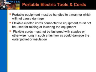
Portable Electric Tools& Cords
Portable equipment must be handled in a manner which
will not cause damage
Flexible electric cords connected to equipment must not
be used for raising or lowering the equipment
Flexible cords must not be fastened with staples or
otherwise hung in such a fashion as could damage the
outer jacket or insulation
53.
Portable Electric Tools& Cords
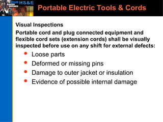
Visual Inspections
Portable cord and plug connected equipment and
flexible cord sets (extension cords) shall be visually
inspected before use on any shift for external defects:
Loose parts
Deformed or missing pins
Damage to outer jacket or insulation
Evidence of possible internal damage
54.
Portable Electric Tools& Cords
If there is a defect or evidence of damage to any electrical
tools or equipment…
Remove the item from service
Tag it for repair
Tell your co-workers
55.
Other Control Measures
Whencarrying out testing with equipment that produces
high voltage/low power outputs the following must be
observed:
Barrier to be erected around test area
Danger Notices to be posted
Inform site personnel of the test
Ensure when test is complete, equipment and circuitry
is discharged using the instruments in-built discharge
circuitry
Confirm the area zone classification and take
appropriate measures
56.
Modifications
Authorised &unauthorised modifications must be
identified and recorded
Modifications should be considered to determine
whether or not it is safe to proceed with the task
The Supervisor should be consulted where necessary
Details of modifications & remedial action should be
recorded on the checklist
Instructions are to be provided to serviceman making
modifications in the field
Supervisor is to be responsible for the actions of the
serviceman’s modifications in the field
Reference may be made to the BHI “Management of
Change” procedure
57.
Portable Electric Tools& Cords
Portable equipment must be handled in a manner which
will not cause damage.
Flexible electric cords connected to equipment may not
be used for raising or lowering the equipment.
Flexible cords may not be fastened with staples or
otherwise hung in such a fashion as could damage the
outer jacket or insulation.
58.
Work Area Safety
Youmust be able to see what you are doing
when working on energized equipment
Do not work on energized electrical parts
without adequate illumination
if there is an obstruction that prevents
seeing your work area
if you must reach blindly into areas which
may contain energized parts
59.
Signs & Barricades
Use safety signs, safety symbols, or accident prevention
tags to warn others about electrical hazards
Use barricades to prevent or limit access to work areas
with un-insulated energized conductors or circuit parts
Insert pics of safety signs etc
60.
Hazardous Work Locations
Electric equipment & flexible cords used in
highly conductive work locations where
employees are likely to contact water or
conductive liquids, must be rated for the wet
environment (RCD/GFCI)
Electric equipment used in areas where
flammable or explosive atmospheres are
present must be rated for these locations (i.e.
intrinsically safe, etc.)
61.
How To Respondto an Accident
Response to Electrical Shock
Don’t touch the person and don’t use a conductive tool to free
the person – he or she might be energized
Shut off the power, fuse or circuit-breaker or pull the plug. This
might be difficult because there might be secondary sources. If
you are not sure, get help
Remove the person from the contact point using a non-
conductive object such as a dry piece of wood or Safety
Evacuation Hook thingy
62.
How To Respondto an Accident
Response to Electrical Shock
Secure the area and keep others from
being harmed
Do not move the injured person unless it
is absolutely necessary to do so (e.g. case
of fire)
Give necessary first aid and CPR, if
trained to do so
Report accidents to your supervisor (even
minor shocks and close calls must be
reported).
Where possible, preserve the evidence to
assist in the incident investigation