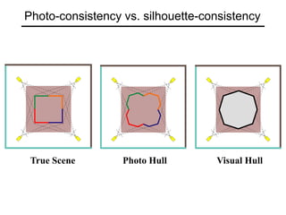
Last time: Binocular stereo
image 1 image 2
Dense depth map
Review: Binocular stereo
• The basic stereo matching algorithm
• Similarity constraint
• No coherence enforced between matches
• Non-local constraints
• Uniqueness, ordering, smoothness
• Scanline stereo
• Coherent optimization of all matches along an entire
scanline, independent optimization of different scanlines
• Dynamic programming
• Coherent 2D stereo
• Energy minimization
• Approximate solutions found via graph cuts
• Model-based stereo
• Active stereo
Multi-view stereo
Many slides adapted from S. Seitz
What is stereo vision?
• Generic problem formulation: given several images of
the same object or scene, compute a representation of
its 3D shape
What is stereo vision?
• Generic problem formulation: given several images of
the same object or scene, compute a representation of
its 3D shape
• “Images of the same object or scene”
• Arbitrary number of images (from two to thousands)
• Arbitrary camera positions (isolated cameras or video sequence)
• Cameras can be calibrated or uncalibrated
• “Representation of 3D shape”
• Depth maps
• Meshes
• Point clouds
• Patch clouds
• Volumetric models
• Layered models
The third view can be used for verification
Beyond two-view stereo
• Pick a reference image, and slide the corresponding
window along the corresponding epipolar lines of all
other images, using inverse depth relative to the first
image as the search parameter
M. Okutomi and T. Kanade, “A Multiple-Baseline Stereo System,” IEEE Trans. on
Pattern Analysis and Machine Intelligence, 15(4):353-363 (1993).
Multiple-baseline stereo
• For larger baselines, must search larger
area in second image
1/z
width of
a pixel
width of
a pixel
1/z
pixel matching score
Multiple-baseline stereo
Use the sum of
SSD scores to rank
matches
I1 I2 I10
Multiple-baseline stereo results
M. Okutomi and T. Kanade, “A Multiple-Baseline Stereo System,” IEEE Trans. on
Pattern Analysis and Machine Intelligence, 15(4):353-363 (1993).
Summary: Multiple-baseline stereo
• Pros
• Using multiple images reduces the ambiguity of matching
• Cons
• Must choose a reference view
• Occlusions become an issue for large baseline
• Possible solution: use a virtual view
Plane Sweep Stereo
• Choose a virtual view
• Sweep family of planes at different depths with
respect to the virtual camera
each plane defines an image ⇒ composite homography
virtual camera
composite
input image
R. Collins. A space-sweep approach to true multi-image matching. CVPR 1996.
input image
Plane Sweep Stereo
• For each depth plane
• For each pixel in the composite image, compute the variance
• For each pixel, select the depth that gives the lowest variance
Plane Sweep Stereo
• For each depth plane
• For each pixel in the composite image, compute the variance
• For each pixel, select the depth that gives the lowest variance
Can be accelerated using graphics hardware
R. Yang and M. Pollefeys. Multi-Resolution Real-Time Stereo on Commodity Graphics
Hardware, CVPR 2003
Volumetric stereo
• In plane sweep stereo, the sampling of the scene
still depends on the reference view
• We can use a voxel volume to get a view-
independent representation
Volumetric stereo
Scene Volume
V
Input Images
(Calibrated)
Goal: Determine occupancy, “color” of points in V
Discrete formulation: Voxel Coloring
Discretized
Scene Volume
Input Images
(Calibrated)
Goal: Assign RGB values to voxels in V
photo-consistent with images
Photo-consistency
All Scenes
Photo-Consistent
Scenes
True
Scene
• A photo-consistent scene is a scene that exactly
reproduces your input images from the same camera
viewpoints
• You can’t use your input cameras and images to tell
the difference between a photo-consistent scene and
the true scene
Space Carving
Space Carving Algorithm
Image 1 Image N
…...
• Initialize to a volume V containing the true scene
• Repeat until convergence
• Choose a voxel on the current surface
• Carve if not photo-consistent
• Project to visible input images
K. N. Kutulakos and S. M. Seitz, A Theory of Shape by Space Carving, ICCV 1999
Which shape do you get?
The Photo Hull is the UNION of all photo-consistent scenes in V
• It is a photo-consistent scene reconstruction
• Tightest possible bound on the true scene
True Scene
V
Photo Hull
V
Source: S. Seitz
Space Carving Results: African Violet
Input Image (1 of 45) Reconstruction
Reconstruction
Reconstruction Source: S. Seitz
Space Carving Results: Hand
Input Image
(1 of 100)
Views of Reconstruction
Reconstruction from Silhouettes
Binary Images
• The case of binary images: a voxel is photo-
consistent if it lies inside the object’s silhouette in all
views
Reconstruction from Silhouettes
Binary Images
Finding the silhouette-consistent shape (visual hull):
• Backproject each silhouette
• Intersect backprojected volumes
• The case of binary images: a voxel is photo-
consistent if it lies inside the object’s silhouette in all
views
Volume intersection
Reconstruction Contains the True Scene
• But is generally not the same
Voxel algorithm for volume intersection
Color voxel black if on silhouette in every image
Properties of Volume Intersection
• Pros
• Easy to implement, fast
• Cons
• No concavities
Properties of Volume Intersection
• Pros
• Easy to implement, fast
• Cons
• No concavities
• Reconstruction is not photo-consistent if texture information
is available
• Requires silhouette extraction
Photo-consistency vs. silhouette-consistency
True Scene Photo Hull Visual Hull
Polyhedral volume intersection
B. Baumgart, Geometric Modeling for Computer Vision, Stanford Artificial Intelligence
Laboratory, Memo no. AIM-249, Stanford University, October 1974.
Polyhedral volume intersection: Pros and cons
• Pros
• No voxelization artifacts
• Cons
• Depends on discretization of outlines
• Numerical problems when polygons to be intersected are
almost coplanar
• Does not take advantage of epipolar geometry
Image-based visual hulls
Wojciech Matusik, Christopher Buehler, Ramesh Raskar, Steven Gortler, and Leonard
McMillan. Image-based Visual Hulls. In SIGGRAPH 2000
Virtual view
• Pick a pixel in the virtual view
• Project corresponding visual
ray into every other view to get
a set of epipolar lines
• Find intervals where epipolar
lines overlap with silhouettes
• Lift intervals back onto the 3D
ray and find their intersection
Image-based visual hulls
Wojciech Matusik, Christopher Buehler, Ramesh Raskar, Steven Gortler, and Leonard
McMillan. Image-based Visual Hulls. In SIGGRAPH 2000
Image-based visual hulls: Pros and cons
• Pros
• Can work in real time
• Takes advantage of epipolar geometry
• Cons
• Need to recompute the visual hull every time the virtual view
is changed
Carved visual hulls
• The visual hull is a good starting point for optimizing
photo-consistency
• Easy to compute
• Tight outer boundary of the object
• Parts of the visual hull (rims) already lie on the surface and are
already photo-consistent
Yasutaka Furukawa and Jean Ponce, Carved Visual Hulls for Image-Based
Modeling, ECCV 2006.
Carved visual hulls
1. Compute visual hull
2. Use dynamic programming to find rims and
constrain them to be fixed
3. Carve the visual hull to optimize photo-consistency
Yasutaka Furukawa and Jean Ponce, Carved Visual Hulls for Image-Based
Modeling, ECCV 2006.
Carved visual hulls
Yasutaka Furukawa and Jean Ponce, Carved Visual Hulls for Image-Based
Modeling, ECCV 2006.
Carved visual hulls: Pros and cons
• Pros
• Visual hull gives a reasonable initial mesh that can be
iteratively deformed
• Cons
• Need silhouette extraction
• Have to compute a lot of points that don’t lie on the object
• Finding rims is difficult
• The carving step can get caught in local minima
• Possible solution: use sparse feature
correspondences as initialization
Feature-based stereo matching
T. Tuytelaars and L. Van Gool, "Matching Widely Separated Views based on Affine
Invariant Regions" Int. Journal on Computer Vision, 59(1), pp. 61-85, 2004.
Feature-based stereo matching
• Pros
• Robust to clutter and occlusion
• Only find matches at reliable points
• Can use invariant local features to deal with foreshortening,
scale change, wide baselines
• Cons
• You only get a sparse cloud of points (or oriented patches),
not a dense depth map or a complete surface
From feature matching to dense stereo
1. Extract features
2. Get a sparse set of initial matches
3. Iteratively expand matches to nearby locations
4. Use visibility constraints to filter out false matches
5. Perform surface reconstruction
Yasutaka Furukawa and Jean Ponce, Accurate, Dense, and Robust Multi-View
Stereopsis, CVPR 2007.
From feature matching to dense stereo
Yasutaka Furukawa and Jean Ponce, Accurate, Dense, and Robust Multi-View
Stereopsis, CVPR 2007.
http://www.cs.washington.edu/homes/furukawa/gallery/
Stereo from community photo collections
M. Goesele, N. Snavely, B. Curless, H. Hoppe, S. Seitz, Multi-View Stereo for
Community Photo Collections, ICCV 2007
http://grail.cs.washington.edu/projects/mvscpc/
Stereo from community photo collections
M. Goesele, N. Snavely, B. Curless, H. Hoppe, S. Seitz, Multi-View Stereo for
Community Photo Collections, ICCV 2007
stereo laser scan
Comparison: 90% of points
within 0.128 m of laser scan
(building height 51m)
Stereo from community photo collections
• Up to now, we’ve always assumed that camera
calibration is known
• For photos taken from the Internet, we need structure
from motion techniques to reconstruct both camera
positions and 3D points
Multi-view stereo: Summary
• Multiple-baseline stereo
• Pick one input view as reference
• Inverse depth instead of disparity
• Plane sweep stereo
• Virtual view
• Volumetric stereo
• Photo-consistency
• Space carving
• Shape from silhouettes
• Visual hull: intersection of visual cones
• Volumetric, polyhedral, image-based
• Carved visual hulls
• Feature-based stereo
• From sparse to dense correspondences

Lec14 multiview stereo

  • 1.
    Last time: Binocularstereo image 1 image 2 Dense depth map
  • 2.
    Review: Binocular stereo •The basic stereo matching algorithm • Similarity constraint • No coherence enforced between matches • Non-local constraints • Uniqueness, ordering, smoothness • Scanline stereo • Coherent optimization of all matches along an entire scanline, independent optimization of different scanlines • Dynamic programming • Coherent 2D stereo • Energy minimization • Approximate solutions found via graph cuts • Model-based stereo • Active stereo
  • 3.
    Multi-view stereo Many slidesadapted from S. Seitz
  • 4.
    What is stereovision? • Generic problem formulation: given several images of the same object or scene, compute a representation of its 3D shape
  • 5.
    What is stereovision? • Generic problem formulation: given several images of the same object or scene, compute a representation of its 3D shape • “Images of the same object or scene” • Arbitrary number of images (from two to thousands) • Arbitrary camera positions (isolated cameras or video sequence) • Cameras can be calibrated or uncalibrated • “Representation of 3D shape” • Depth maps • Meshes • Point clouds • Patch clouds • Volumetric models • Layered models
  • 6.
    The third viewcan be used for verification Beyond two-view stereo
  • 7.
    • Pick areference image, and slide the corresponding window along the corresponding epipolar lines of all other images, using inverse depth relative to the first image as the search parameter M. Okutomi and T. Kanade, “A Multiple-Baseline Stereo System,” IEEE Trans. on Pattern Analysis and Machine Intelligence, 15(4):353-363 (1993). Multiple-baseline stereo
  • 8.
    Multiple-baseline stereo • Forlarger baselines, must search larger area in second image 1/z width of a pixel width of a pixel 1/z pixel matching score
  • 9.
    Multiple-baseline stereo Use thesum of SSD scores to rank matches
  • 10.
    I1 I2 I10 Multiple-baselinestereo results M. Okutomi and T. Kanade, “A Multiple-Baseline Stereo System,” IEEE Trans. on Pattern Analysis and Machine Intelligence, 15(4):353-363 (1993).
  • 11.
    Summary: Multiple-baseline stereo •Pros • Using multiple images reduces the ambiguity of matching • Cons • Must choose a reference view • Occlusions become an issue for large baseline • Possible solution: use a virtual view
  • 12.
    Plane Sweep Stereo •Choose a virtual view • Sweep family of planes at different depths with respect to the virtual camera each plane defines an image ⇒ composite homography virtual camera composite input image R. Collins. A space-sweep approach to true multi-image matching. CVPR 1996. input image
  • 13.
    Plane Sweep Stereo •For each depth plane • For each pixel in the composite image, compute the variance • For each pixel, select the depth that gives the lowest variance
  • 14.
    Plane Sweep Stereo •For each depth plane • For each pixel in the composite image, compute the variance • For each pixel, select the depth that gives the lowest variance Can be accelerated using graphics hardware R. Yang and M. Pollefeys. Multi-Resolution Real-Time Stereo on Commodity Graphics Hardware, CVPR 2003
  • 15.
    Volumetric stereo • Inplane sweep stereo, the sampling of the scene still depends on the reference view • We can use a voxel volume to get a view- independent representation
  • 16.
    Volumetric stereo Scene Volume V InputImages (Calibrated) Goal: Determine occupancy, “color” of points in V
  • 17.
    Discrete formulation: VoxelColoring Discretized Scene Volume Input Images (Calibrated) Goal: Assign RGB values to voxels in V photo-consistent with images
  • 18.
    Photo-consistency All Scenes Photo-Consistent Scenes True Scene • Aphoto-consistent scene is a scene that exactly reproduces your input images from the same camera viewpoints • You can’t use your input cameras and images to tell the difference between a photo-consistent scene and the true scene
  • 19.
    Space Carving Space CarvingAlgorithm Image 1 Image N …... • Initialize to a volume V containing the true scene • Repeat until convergence • Choose a voxel on the current surface • Carve if not photo-consistent • Project to visible input images K. N. Kutulakos and S. M. Seitz, A Theory of Shape by Space Carving, ICCV 1999
  • 20.
    Which shape doyou get? The Photo Hull is the UNION of all photo-consistent scenes in V • It is a photo-consistent scene reconstruction • Tightest possible bound on the true scene True Scene V Photo Hull V Source: S. Seitz
  • 21.
    Space Carving Results:African Violet Input Image (1 of 45) Reconstruction Reconstruction Reconstruction Source: S. Seitz
  • 22.
    Space Carving Results:Hand Input Image (1 of 100) Views of Reconstruction
  • 23.
    Reconstruction from Silhouettes BinaryImages • The case of binary images: a voxel is photo- consistent if it lies inside the object’s silhouette in all views
  • 24.
    Reconstruction from Silhouettes BinaryImages Finding the silhouette-consistent shape (visual hull): • Backproject each silhouette • Intersect backprojected volumes • The case of binary images: a voxel is photo- consistent if it lies inside the object’s silhouette in all views
  • 25.
    Volume intersection Reconstruction Containsthe True Scene • But is generally not the same
  • 26.
    Voxel algorithm forvolume intersection Color voxel black if on silhouette in every image
  • 27.
    Properties of VolumeIntersection • Pros • Easy to implement, fast • Cons • No concavities
  • 28.
    Properties of VolumeIntersection • Pros • Easy to implement, fast • Cons • No concavities • Reconstruction is not photo-consistent if texture information is available • Requires silhouette extraction
  • 29.
  • 30.
    Polyhedral volume intersection B.Baumgart, Geometric Modeling for Computer Vision, Stanford Artificial Intelligence Laboratory, Memo no. AIM-249, Stanford University, October 1974.
  • 31.
    Polyhedral volume intersection:Pros and cons • Pros • No voxelization artifacts • Cons • Depends on discretization of outlines • Numerical problems when polygons to be intersected are almost coplanar • Does not take advantage of epipolar geometry
  • 32.
    Image-based visual hulls WojciechMatusik, Christopher Buehler, Ramesh Raskar, Steven Gortler, and Leonard McMillan. Image-based Visual Hulls. In SIGGRAPH 2000 Virtual view • Pick a pixel in the virtual view • Project corresponding visual ray into every other view to get a set of epipolar lines • Find intervals where epipolar lines overlap with silhouettes • Lift intervals back onto the 3D ray and find their intersection
  • 33.
    Image-based visual hulls WojciechMatusik, Christopher Buehler, Ramesh Raskar, Steven Gortler, and Leonard McMillan. Image-based Visual Hulls. In SIGGRAPH 2000
  • 34.
    Image-based visual hulls:Pros and cons • Pros • Can work in real time • Takes advantage of epipolar geometry • Cons • Need to recompute the visual hull every time the virtual view is changed
  • 35.
    Carved visual hulls •The visual hull is a good starting point for optimizing photo-consistency • Easy to compute • Tight outer boundary of the object • Parts of the visual hull (rims) already lie on the surface and are already photo-consistent Yasutaka Furukawa and Jean Ponce, Carved Visual Hulls for Image-Based Modeling, ECCV 2006.
  • 36.
    Carved visual hulls 1.Compute visual hull 2. Use dynamic programming to find rims and constrain them to be fixed 3. Carve the visual hull to optimize photo-consistency Yasutaka Furukawa and Jean Ponce, Carved Visual Hulls for Image-Based Modeling, ECCV 2006.
  • 37.
    Carved visual hulls YasutakaFurukawa and Jean Ponce, Carved Visual Hulls for Image-Based Modeling, ECCV 2006.
  • 38.
    Carved visual hulls:Pros and cons • Pros • Visual hull gives a reasonable initial mesh that can be iteratively deformed • Cons • Need silhouette extraction • Have to compute a lot of points that don’t lie on the object • Finding rims is difficult • The carving step can get caught in local minima • Possible solution: use sparse feature correspondences as initialization
  • 39.
    Feature-based stereo matching T.Tuytelaars and L. Van Gool, "Matching Widely Separated Views based on Affine Invariant Regions" Int. Journal on Computer Vision, 59(1), pp. 61-85, 2004.
  • 40.
    Feature-based stereo matching •Pros • Robust to clutter and occlusion • Only find matches at reliable points • Can use invariant local features to deal with foreshortening, scale change, wide baselines • Cons • You only get a sparse cloud of points (or oriented patches), not a dense depth map or a complete surface
  • 41.
    From feature matchingto dense stereo 1. Extract features 2. Get a sparse set of initial matches 3. Iteratively expand matches to nearby locations 4. Use visibility constraints to filter out false matches 5. Perform surface reconstruction Yasutaka Furukawa and Jean Ponce, Accurate, Dense, and Robust Multi-View Stereopsis, CVPR 2007.
  • 42.
    From feature matchingto dense stereo Yasutaka Furukawa and Jean Ponce, Accurate, Dense, and Robust Multi-View Stereopsis, CVPR 2007. http://www.cs.washington.edu/homes/furukawa/gallery/
  • 43.
    Stereo from communityphoto collections M. Goesele, N. Snavely, B. Curless, H. Hoppe, S. Seitz, Multi-View Stereo for Community Photo Collections, ICCV 2007 http://grail.cs.washington.edu/projects/mvscpc/
  • 44.
    Stereo from communityphoto collections M. Goesele, N. Snavely, B. Curless, H. Hoppe, S. Seitz, Multi-View Stereo for Community Photo Collections, ICCV 2007 stereo laser scan Comparison: 90% of points within 0.128 m of laser scan (building height 51m)
  • 45.
    Stereo from communityphoto collections • Up to now, we’ve always assumed that camera calibration is known • For photos taken from the Internet, we need structure from motion techniques to reconstruct both camera positions and 3D points
  • 46.
    Multi-view stereo: Summary •Multiple-baseline stereo • Pick one input view as reference • Inverse depth instead of disparity • Plane sweep stereo • Virtual view • Volumetric stereo • Photo-consistency • Space carving • Shape from silhouettes • Visual hull: intersection of visual cones • Volumetric, polyhedral, image-based • Carved visual hulls • Feature-based stereo • From sparse to dense correspondences