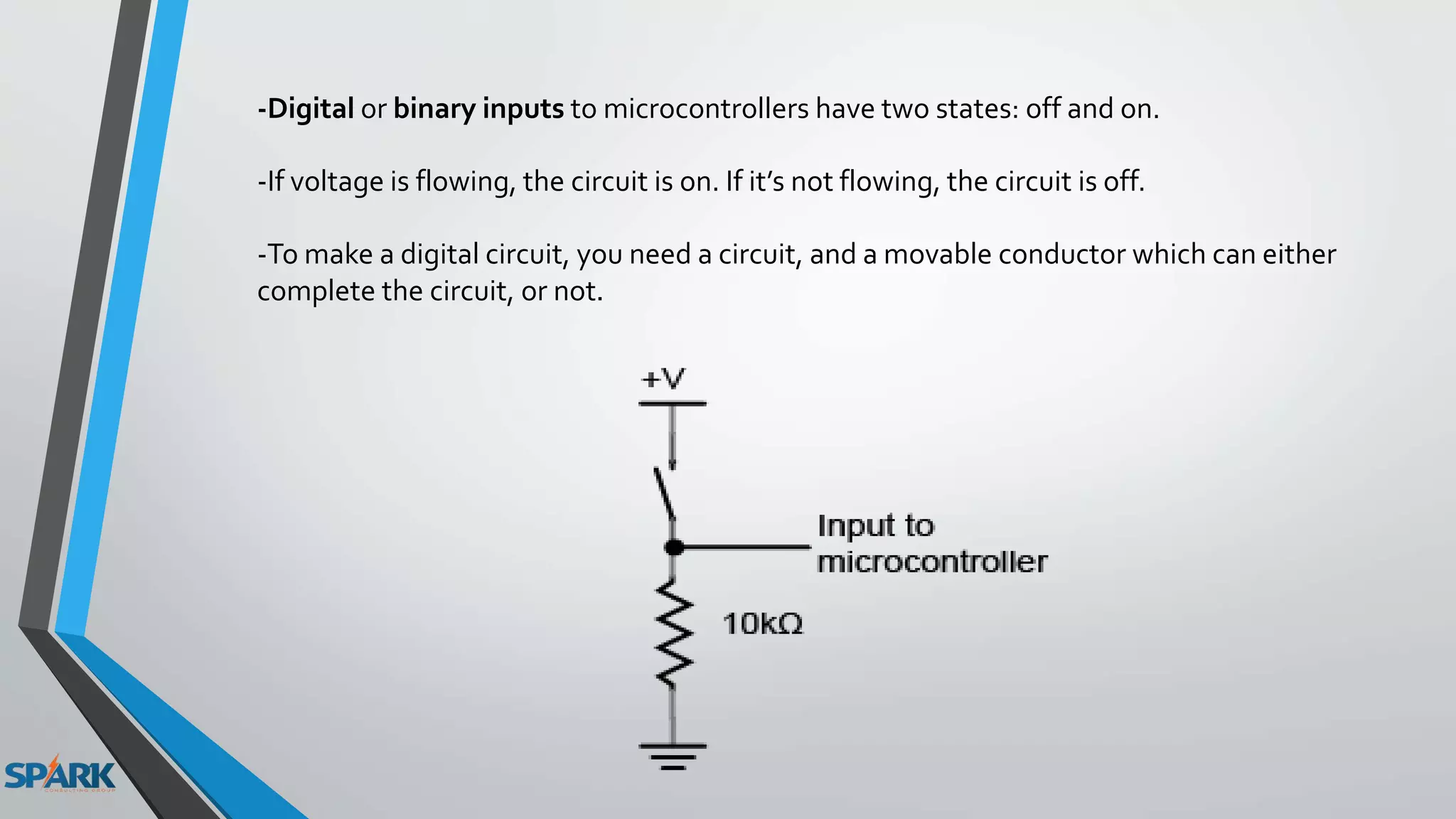
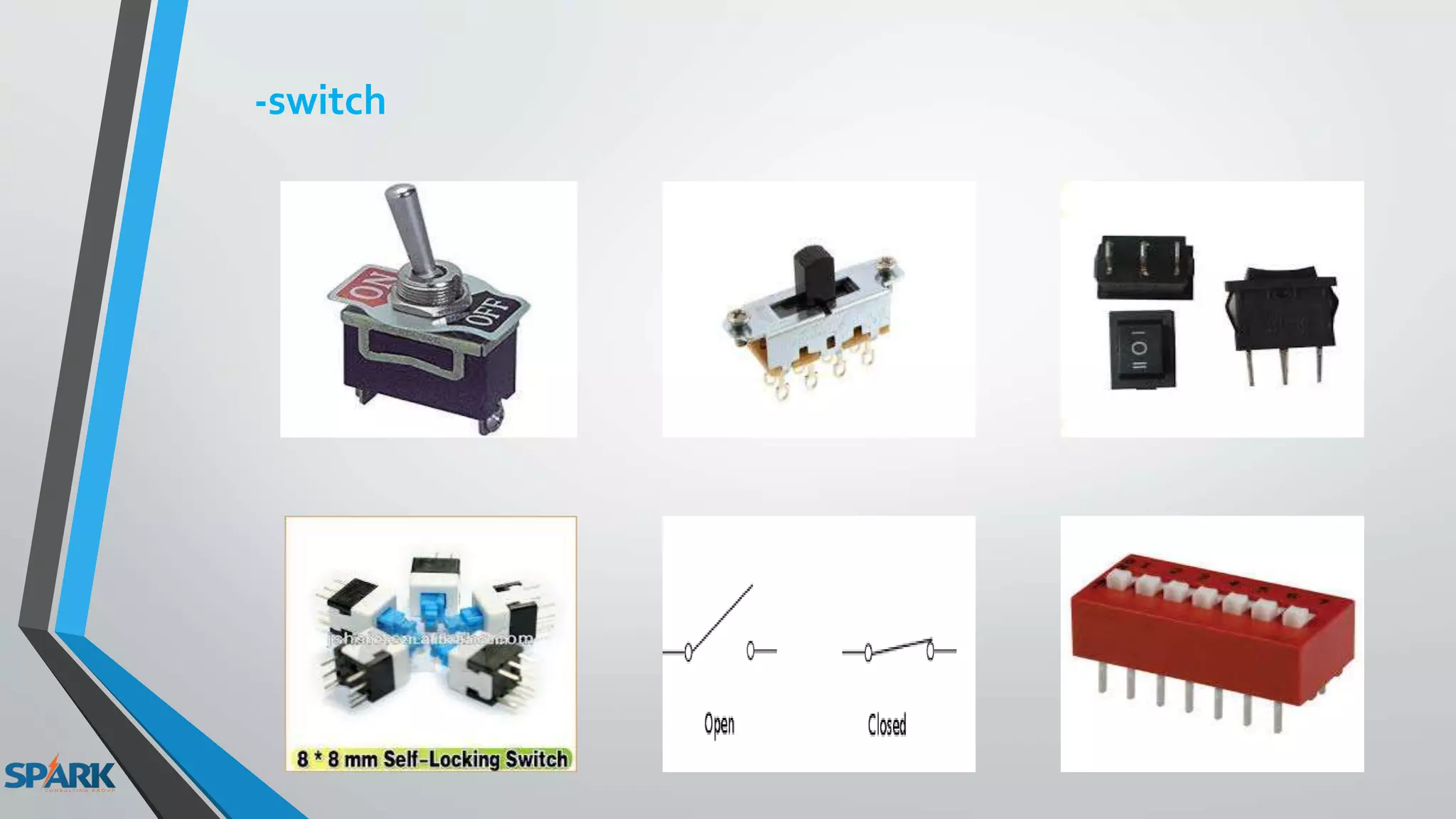
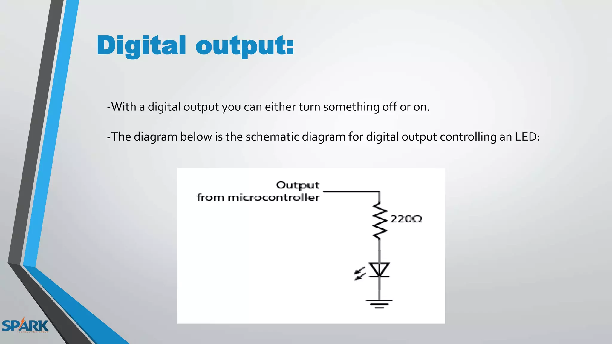
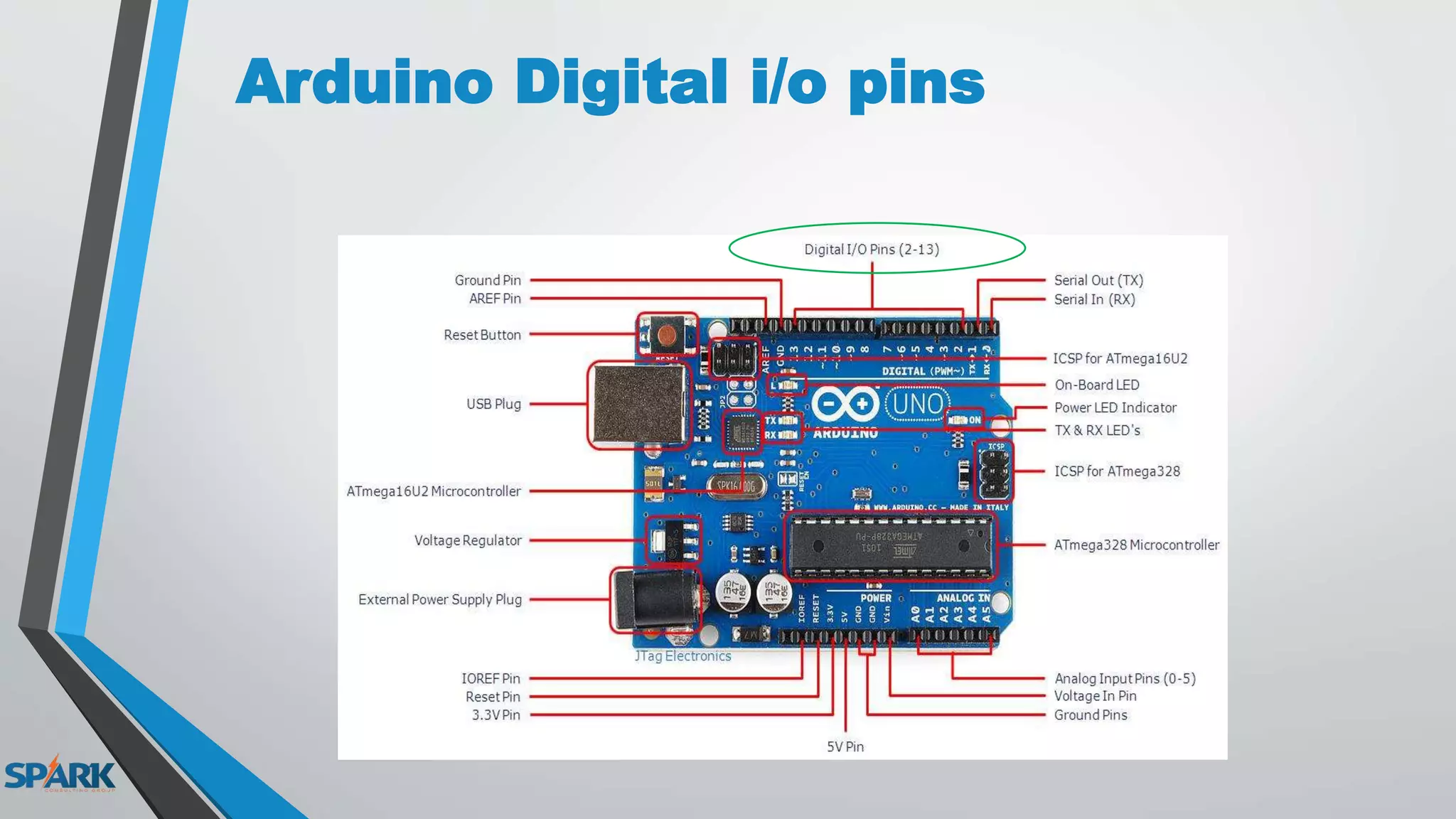
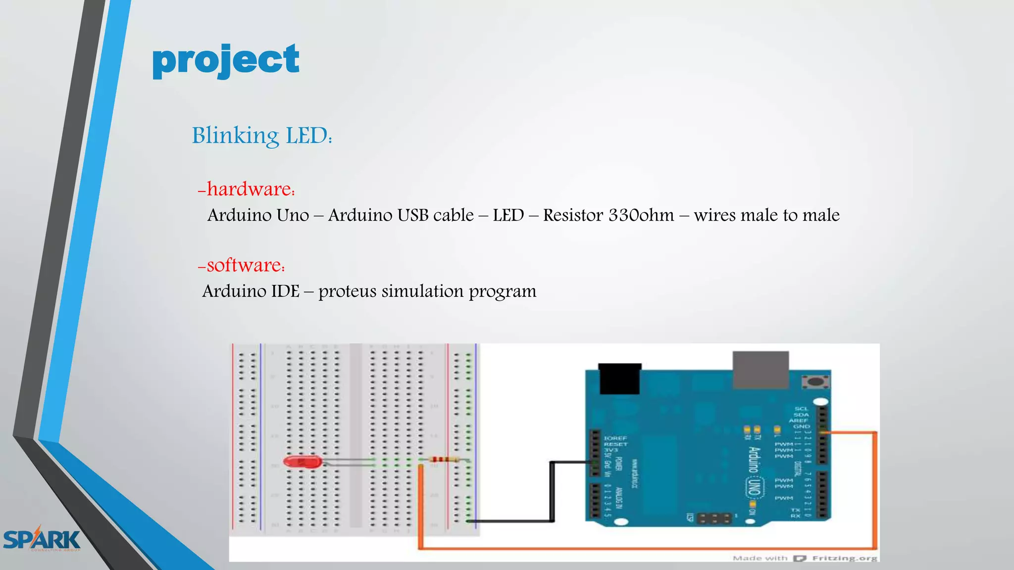
ARDUINO COURSE
Collected By : MohamedZain Allam
Lecture 3
Digital I/O
Digital signal:
Digital signals must have a finite set of possible values.
The number of values in the set can be anywhere between two and a-very-large-number-
that’s-not-infinity.
Most commonly digital signals will be one of two values – like either 0V or 5V.
Timing graphs of these signals look like square waves.
Digital Inputs:
-When you’re trying to sense activity in the physical world using a microcontroller
-the simplest activities you can sense are those in which you only need to know one thing
about the physical world: Whether something is true or false.
-Is the viewer in the room or out? Are they touching the table or not? Is the door open or
closed?
-you can determine what you need to know using a digital input, or switch.
-Digital or binary inputs to microcontrollers have two states: off and on.
-If voltage is flowing, the circuit is on. If it’s not flowing, the circuit is off.
-To make a digital circuit, you need a circuit, and a movable conductor which can either
complete the circuit, or not.
Sources of digital input:
-Push Button
-switch
-Digital Sensors
Digital output:
-With a digital output you can either turn something off or on.
-The diagram below is the schematic diagram for digital output controlling an LED:
Examples of digital output
-LED
How to calculate the resistor value ?
-LED current equal from 10 to 20 mA (14mA)
-LED voltage equal 2v
-Arduino output current = 40 mA
-Arduino output Voltage = 5V
- Ohm’s law ( V = I * R ).
-R=V/I R=(5-2)/(14*10^-3) = 214 ohm
- From the values of the resistors in the stores we can use (220,330 ohm)
-the power of the resistor P=I^2 * R P=(14 *10^-3)^2 * 330 = 0.064 W
-LED Matrix:
-Buzzer
Arduino Digital i/o pins
Arduino C
-pinMode(A , INPUT or OUTPUT );
-digitalWrite(A , HIGH or LOW );
-digitalRead(B);
-delay(C);
A : the num. of digital output pin.
B : the num. of digital input pin.
C : the time in millisecond , when second = 1000 m.sec
project
Blinking LED:
-hardware:
Arduino Uno – Arduino USB cable – LED – Resistor 330ohm – wires male to male
-software:
Arduino IDE – proteus simulation program
Hardware Review:
-Test Board :
-Wires:
Female to FemaleMale to Male Male to Female
Resistors:
project
-Traffic Light:
change the color each 0.5 sec
project
-Blinking LED with switch:
Task
Lec 3

Lec 3

  • 1.
    ARDUINO COURSE Collected By: MohamedZain Allam
  • 2.
  • 3.
    Digital signal: Digital signalsmust have a finite set of possible values. The number of values in the set can be anywhere between two and a-very-large-number- that’s-not-infinity. Most commonly digital signals will be one of two values – like either 0V or 5V. Timing graphs of these signals look like square waves.
  • 4.
    Digital Inputs: -When you’retrying to sense activity in the physical world using a microcontroller -the simplest activities you can sense are those in which you only need to know one thing about the physical world: Whether something is true or false. -Is the viewer in the room or out? Are they touching the table or not? Is the door open or closed? -you can determine what you need to know using a digital input, or switch.
  • 5.
    -Digital or binaryinputs to microcontrollers have two states: off and on. -If voltage is flowing, the circuit is on. If it’s not flowing, the circuit is off. -To make a digital circuit, you need a circuit, and a movable conductor which can either complete the circuit, or not.
  • 6.
    Sources of digitalinput: -Push Button
  • 8.
  • 9.
  • 10.
    Digital output: -With adigital output you can either turn something off or on. -The diagram below is the schematic diagram for digital output controlling an LED:
  • 11.
  • 14.
    How to calculatethe resistor value ? -LED current equal from 10 to 20 mA (14mA) -LED voltage equal 2v -Arduino output current = 40 mA -Arduino output Voltage = 5V - Ohm’s law ( V = I * R ). -R=V/I R=(5-2)/(14*10^-3) = 214 ohm - From the values of the resistors in the stores we can use (220,330 ohm) -the power of the resistor P=I^2 * R P=(14 *10^-3)^2 * 330 = 0.064 W
  • 15.
  • 16.
  • 17.
  • 18.
    Arduino C -pinMode(A ,INPUT or OUTPUT ); -digitalWrite(A , HIGH or LOW ); -digitalRead(B); -delay(C); A : the num. of digital output pin. B : the num. of digital input pin. C : the time in millisecond , when second = 1000 m.sec
  • 19.
    project Blinking LED: -hardware: Arduino Uno– Arduino USB cable – LED – Resistor 330ohm – wires male to male -software: Arduino IDE – proteus simulation program
  • 20.
  • 21.
    -Wires: Female to FemaleMaleto Male Male to Female
  • 22.
  • 23.
  • 24.
  • 25.