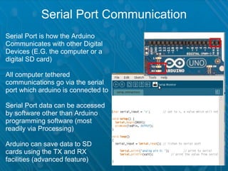
ARDUINO
Open Source

          Open Hardware

A simple computer which can gather input
from reality and interface outputs with the
  environment however you instruct it to

      http://arduinothedocumentary.org/
Fundamentals Of Arduino

• Write sketches or modify existing ones to
  suit your needs
• Wire an electrics circuit
• Upload the sketches to the Arduino (via
  USB connection) and connect the
  electrics circuit to the arduino, by joining
  wires to the sockets on the Arduino board
What is Arduino?

• 5V & GND : sources of power
• Inputs and Outputs
• Data transmission


Nomenclature

• On board sockets = Pins
• Any numbered pin = input
  or output
• TX = transmitting
  RX = receiving
• Arduino AKA microcontroller

                                fig (i)
Sources of Power


                                                    fig (ii)

●
  The arduino has three GND pins and one 5V out
●
  The pins can be used to create a 5v DC circuit,
_sufficient to illuminate an LED (fig ii, above)
●
  A resistor is necessary to ensure the current does not
_burn out the LED
Breadboard: An Arduinos Companion


 ●
   The breadboard holds components external to Arduino
 ●
   Each socket on a breadboard connects to a conductive
 _horizontal or vertical strip
Electrical Circuits


                                                        fig (iii)


  The yellow trail indicates the positive pole of this circuit

  The green trail indicates the common or negative pole

  When both trails are linked by the LED, the circuit is
_completed
The Logic of Switches


                                                   fig (iv)

  The LED does not complete the circuit this time –
_instead a button links the positive and negative poles
_of the circuit

  A button can be pressed (ON) or not pressed (OFF)

  Depending on the buttons state (ON/OFF) the circuit is
_complete or open
Input & Output: Digital

●
    Digital Pin :: input & output
●
    Digital means two possible
    states
        ➢
          HIGH/LOW = ON/OFF
             ➢
               5v – 0v = ON/OFF
●
    Programmed code tells the
    arduino whether each pin is
    HIGH/LOW (aka on/off)

    (The arduino assumes a
    pin to be off until told
    otherwise)
                                      fig (v)
Digital Switches


                                                  fig (vi)

●
  This circuit is the same as fig (ii)
●
  This time the HIGH signal from digital pin 13
_supplies the 5v positive pole to the circuit
Digital Sensors

                    Digital pins detect whether a
                    circuit is in an ON or OFF
                    state
                    When arduino measures
                    voltage in a circuit it will
                    register
                    0 – 2.5v equal to LOW
                    2.5v – 5v equal to HIGH

                    LOW == OFF
                    HIGH == ON

        fig (vii)
Input & Output: Analog
* Analog Pin(s) :: input only
* Analog is different to digital
     *Analog equals continuous
     *Digital equals discreet


* Not just HIGH/LOW
* Instead 0 – 5v is a wider
spectrum of values to measure

0 – 5v = 0 – 1023 in Arduino       fig (viii)
Multimeter: Good Electronics Practice

• Multimeter reads resistance,
  voltage and ampage

• Multimeter is a big help to
  making sure you’re
  electronic circuit works the
  way it should:
• a circuit should always work
  the way you expect it before
  writing/amending arduino
  code
Other Variable Resistors

• LDR
  = Light Dependant Resistor
• Thermistor
  = heat dependant resistor
• GSR
  = Galvanic Skin Response     Galvanic Skin Response
• FSR
  = Force sensitive resistor


                               Thermistor
Serial Port Communication
Serial Port is how the Arduino
Communicates with other Digital       
Devices (E.G. the computer or a
digital SD card)

All computer tethered
communications go via the serial
port which arduino is connected to

Serial Port data can be accessed
by software other than Arduino
programming software (most
readily via Processing)

Arduino can save data to SD
cards using the TX and RX
facilities (advanced feature)

Rebooting Computing chalkwell

  • 1.
  • 2.
    Open Source Open Hardware A simple computer which can gather input from reality and interface outputs with the environment however you instruct it to http://arduinothedocumentary.org/
  • 3.
    Fundamentals Of Arduino •Write sketches or modify existing ones to suit your needs • Wire an electrics circuit • Upload the sketches to the Arduino (via USB connection) and connect the electrics circuit to the arduino, by joining wires to the sockets on the Arduino board
  • 4.
    What is Arduino? •5V & GND : sources of power • Inputs and Outputs • Data transmission Nomenclature • On board sockets = Pins • Any numbered pin = input or output • TX = transmitting RX = receiving • Arduino AKA microcontroller fig (i)
  • 5.
    Sources of Power fig (ii) ● The arduino has three GND pins and one 5V out ● The pins can be used to create a 5v DC circuit, _sufficient to illuminate an LED (fig ii, above) ● A resistor is necessary to ensure the current does not _burn out the LED
  • 6.
    Breadboard: An ArduinosCompanion ● The breadboard holds components external to Arduino ● Each socket on a breadboard connects to a conductive _horizontal or vertical strip
  • 7.
    Electrical Circuits fig (iii)  The yellow trail indicates the positive pole of this circuit  The green trail indicates the common or negative pole  When both trails are linked by the LED, the circuit is _completed
  • 8.
    The Logic ofSwitches fig (iv)  The LED does not complete the circuit this time – _instead a button links the positive and negative poles _of the circuit  A button can be pressed (ON) or not pressed (OFF)  Depending on the buttons state (ON/OFF) the circuit is _complete or open
  • 9.
    Input & Output:Digital ● Digital Pin :: input & output ● Digital means two possible states ➢ HIGH/LOW = ON/OFF ➢ 5v – 0v = ON/OFF ● Programmed code tells the arduino whether each pin is HIGH/LOW (aka on/off) (The arduino assumes a pin to be off until told otherwise) fig (v)
  • 10.
    Digital Switches fig (vi) ● This circuit is the same as fig (ii) ● This time the HIGH signal from digital pin 13 _supplies the 5v positive pole to the circuit
  • 11.
    Digital Sensors Digital pins detect whether a circuit is in an ON or OFF state When arduino measures voltage in a circuit it will register 0 – 2.5v equal to LOW 2.5v – 5v equal to HIGH LOW == OFF HIGH == ON fig (vii)
  • 12.
    Input & Output:Analog * Analog Pin(s) :: input only * Analog is different to digital *Analog equals continuous *Digital equals discreet * Not just HIGH/LOW * Instead 0 – 5v is a wider spectrum of values to measure 0 – 5v = 0 – 1023 in Arduino fig (viii)
  • 13.
    Multimeter: Good ElectronicsPractice • Multimeter reads resistance, voltage and ampage • Multimeter is a big help to making sure you’re electronic circuit works the way it should: • a circuit should always work the way you expect it before writing/amending arduino code
  • 14.
    Other Variable Resistors •LDR = Light Dependant Resistor • Thermistor = heat dependant resistor • GSR = Galvanic Skin Response Galvanic Skin Response • FSR = Force sensitive resistor Thermistor
  • 15.
    Serial Port Communication SerialPort is how the Arduino Communicates with other Digital   Devices (E.G. the computer or a digital SD card) All computer tethered communications go via the serial port which arduino is connected to Serial Port data can be accessed by software other than Arduino programming software (most readily via Processing) Arduino can save data to SD cards using the TX and RX facilities (advanced feature)