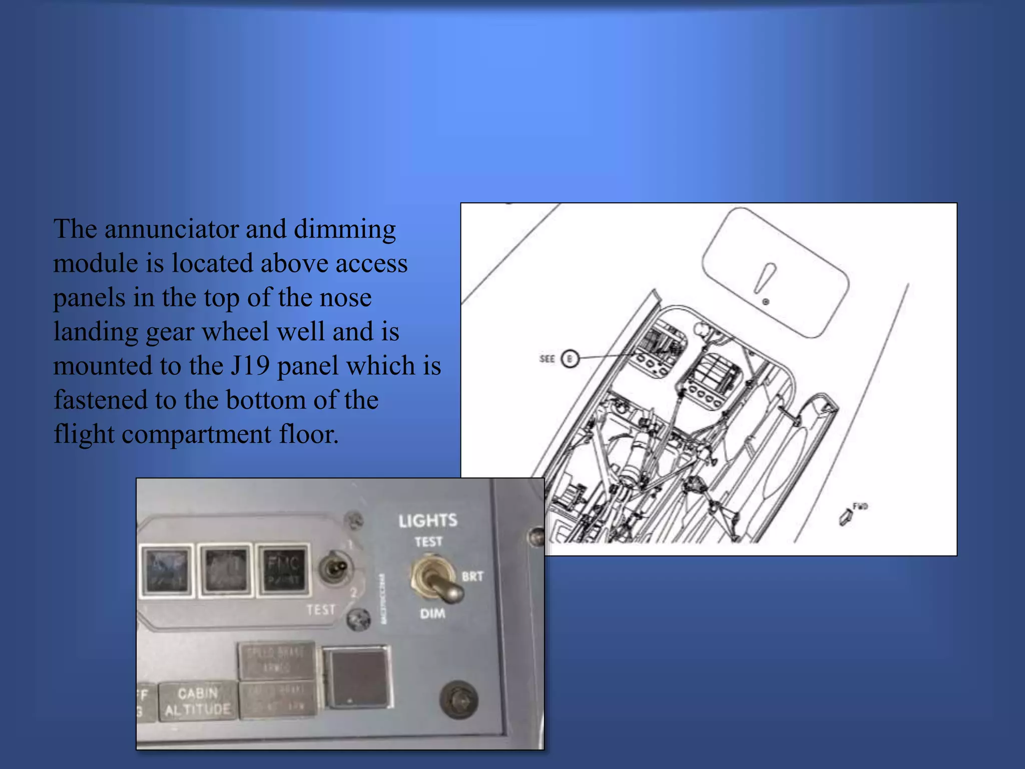
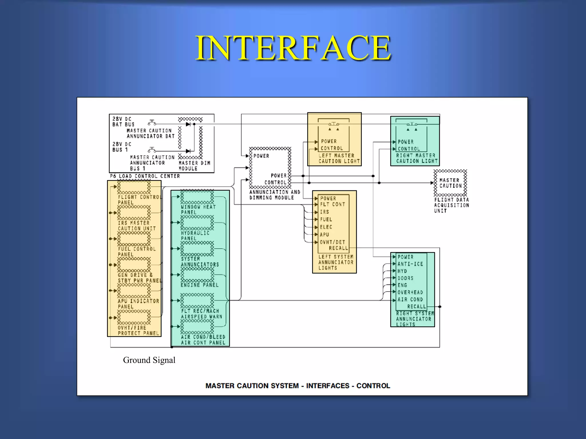
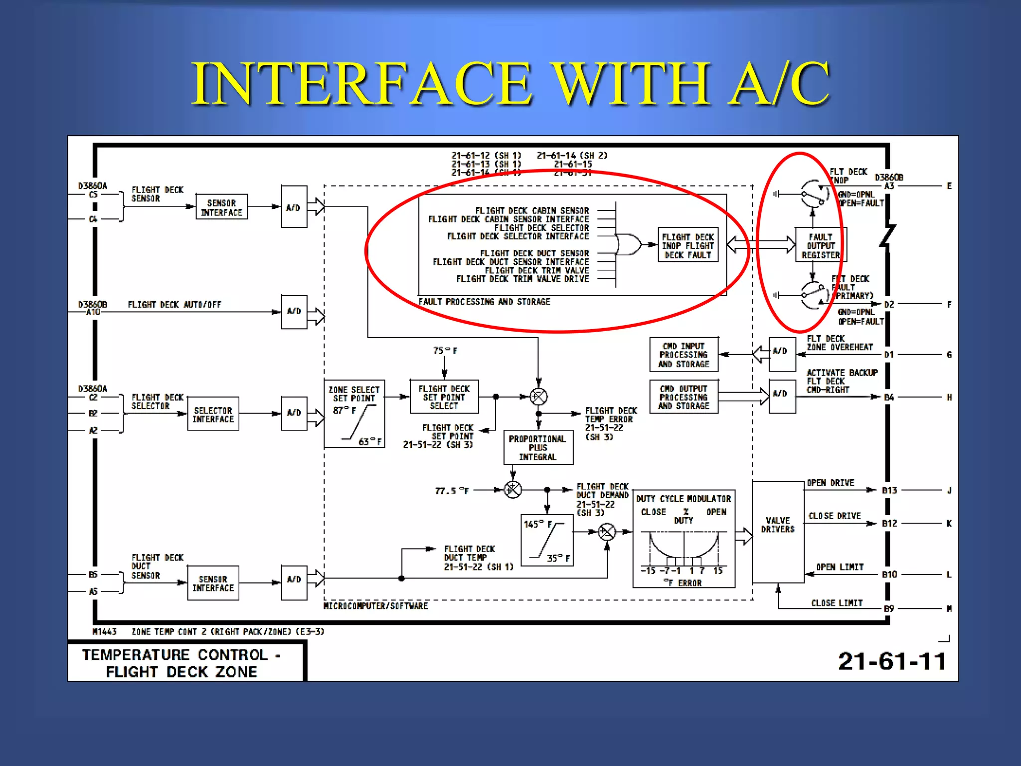
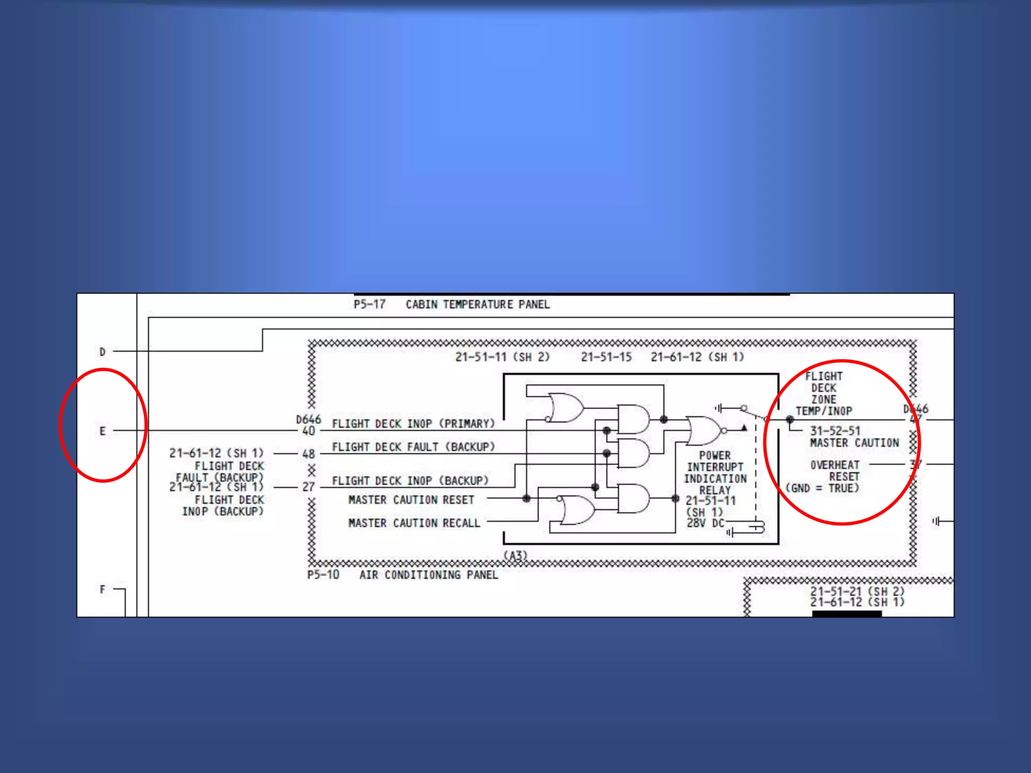
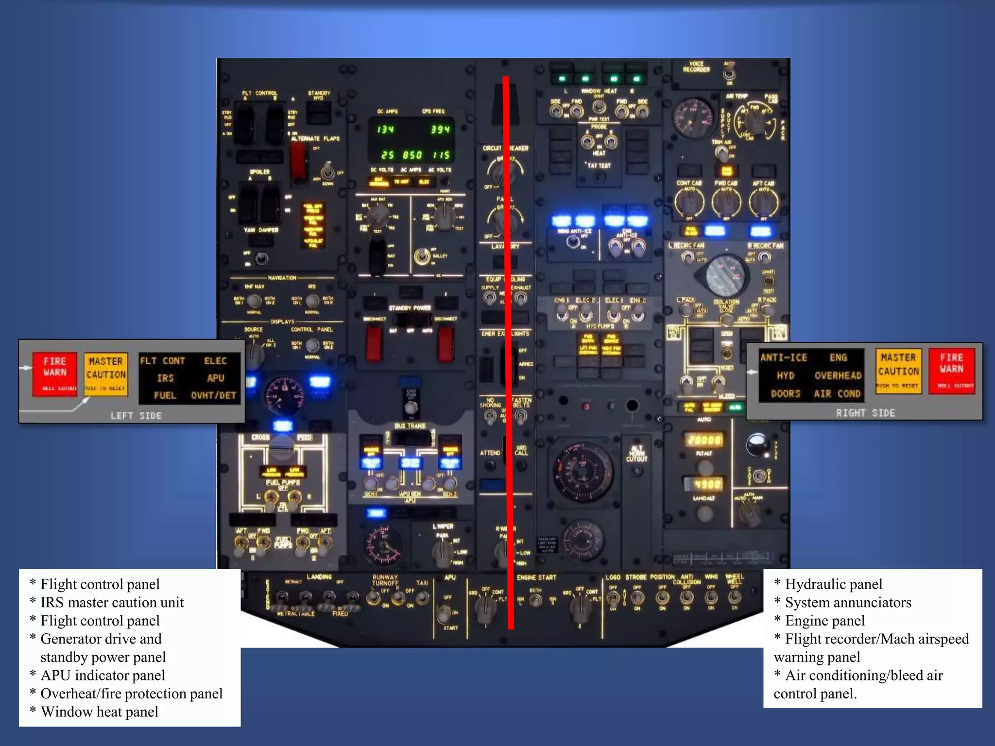
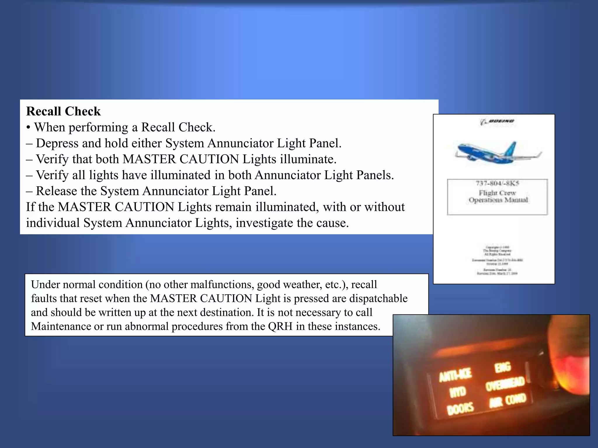
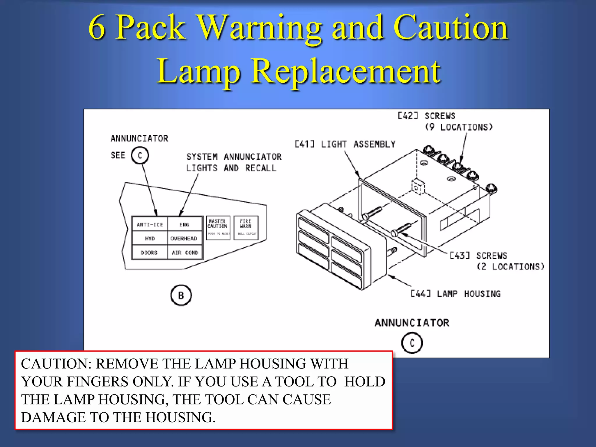
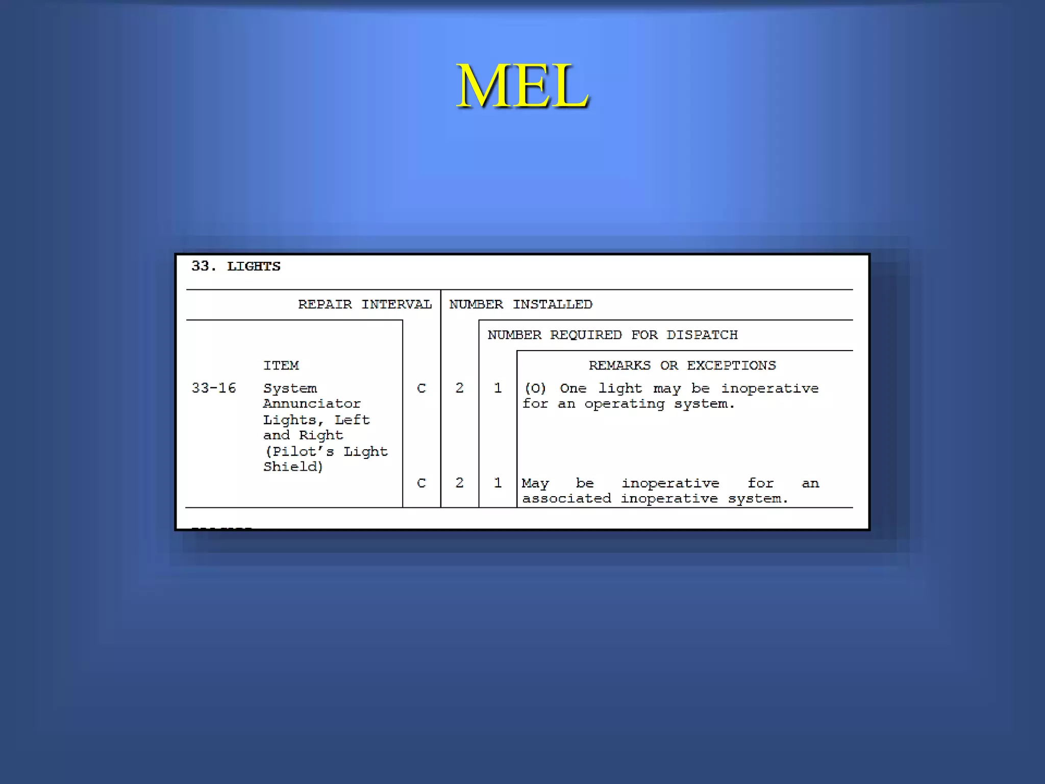
Maintenance & Engineering Training
Q
MASTER WARNING AND
CAUTION
ATA 31
Instructor Information
Instructor
Telephone: (
email:
Class Guidelines
Introductions
Got a train to catch?
Class Guidelines
Class times: 0800-1530
Lunch - 1130-1230
Class Guidelines
Rest Rooms
Class Guidelines
Breaks - Every 45 to 60 minutes
Class Guidelines
Building Safety & Security Considerations
Class Guidelines
Class Sign-In Sheet
Class Participation
Class Guidelines
The material cover on this course is for training and familiarization
purpose only and is not intended to supersede the Manufacturer
Maintenance Manual or any other regulatory approved data. Always
refer to your company procedures and never deviate from approved
Technical Data.
You are always responsible for the work you sign for.
Your SAFETY and those around you must be your #1 priority.
Introductions
• Name
• Company or Organization
• Responsibility
Introductions
Questions ???
General Familiarization and
Line Maintenance Class
for Master Warning and Caution
lights on Boeing 737-800
Student Objectives
QLocate Major Components and Describe
Their Functions
QDescribe Panel Operation and Interface
QDescribe Electrical Power, Control and
Distribution
QDescribe Routine Servicing
QReview MEL and Troubleshooting
Master Warning and Caution
The master caution system provides a visual alert to
the flight crew of unsafe airplane systems operation.
Master Warning and Caution
The annunciator and dimming
module is located above access
panels in the top of the nose
landing gear wheel well and is
mounted to the J19 panel which is
fastened to the bottom of the
flight compartment floor.
INTERFACE
Ground Signal
INTERFACE WITH A/C
* Flight control panel
* IRS master caution unit
* Flight control panel
* Generator drive and
standby power panel
* APU indicator panel
* Overheat/fire protection panel
* Window heat panel
* Hydraulic panel
* System annunciators
* Engine panel
* Flight recorder/Mach airspeed
warning panel
* Air conditioning/bleed air
control panel.
Recall Check
• When performing a Recall Check.
– Depress and hold either System Annunciator Light Panel.
– Verify that both MASTER CAUTION Lights illuminate.
– Verify all lights have illuminated in both Annunciator Light Panels.
– Release the System Annunciator Light Panel.
If the MASTER CAUTION Lights remain illuminated, with or without
individual System Annunciator Lights, investigate the cause.
Under normal condition (no other malfunctions, good weather, etc.), recall
faults that reset when the MASTER CAUTION Light is pressed are dispatchable
and should be written up at the next destination. It is not necessary to call
Maintenance or run abnormal procedures from the QRH in these instances.
ANNUNCIATION LIGHT
RESET and RECALL
46S
6 Pack Warning and Caution
Lamp Replacement
CAUTION: REMOVE THE LAMP HOUSING WITH
YOUR FINGERS ONLY. IF YOU USE A TOOL TO HOLD
THE LAMP HOUSING, THE TOOL CAN CAUSE
DAMAGE TO THE HOUSING.
MEL
REVIEW
• The six pack lights are control by applying voltage or ground?
• What side is the hydraulic warning for the six-pack indicator located?
• What controls the brightness of the warning indication system?
Q&A
15 Minutes 737 warning-lights-presentation

15 Minutes 737 warning-lights-presentation

  • 2.
    Maintenance & EngineeringTraining Q MASTER WARNING AND CAUTION ATA 31
  • 3.
  • 4.
  • 5.
    Got a trainto catch? Class Guidelines Class times: 0800-1530
  • 6.
  • 7.
  • 8.
    Breaks - Every45 to 60 minutes Class Guidelines
  • 9.
    Building Safety &Security Considerations Class Guidelines Class Sign-In Sheet
  • 10.
  • 11.
    The material coveron this course is for training and familiarization purpose only and is not intended to supersede the Manufacturer Maintenance Manual or any other regulatory approved data. Always refer to your company procedures and never deviate from approved Technical Data. You are always responsible for the work you sign for. Your SAFETY and those around you must be your #1 priority.
  • 12.
  • 13.
    • Name • Companyor Organization • Responsibility Introductions
  • 14.
  • 15.
    General Familiarization and LineMaintenance Class for Master Warning and Caution lights on Boeing 737-800
  • 16.
    Student Objectives QLocate MajorComponents and Describe Their Functions QDescribe Panel Operation and Interface QDescribe Electrical Power, Control and Distribution QDescribe Routine Servicing QReview MEL and Troubleshooting
  • 17.
    Master Warning andCaution The master caution system provides a visual alert to the flight crew of unsafe airplane systems operation.
  • 18.
  • 19.
    The annunciator anddimming module is located above access panels in the top of the nose landing gear wheel well and is mounted to the J19 panel which is fastened to the bottom of the flight compartment floor.
  • 20.
  • 21.
  • 23.
    * Flight controlpanel * IRS master caution unit * Flight control panel * Generator drive and standby power panel * APU indicator panel * Overheat/fire protection panel * Window heat panel * Hydraulic panel * System annunciators * Engine panel * Flight recorder/Mach airspeed warning panel * Air conditioning/bleed air control panel.
  • 24.
    Recall Check • Whenperforming a Recall Check. – Depress and hold either System Annunciator Light Panel. – Verify that both MASTER CAUTION Lights illuminate. – Verify all lights have illuminated in both Annunciator Light Panels. – Release the System Annunciator Light Panel. If the MASTER CAUTION Lights remain illuminated, with or without individual System Annunciator Lights, investigate the cause. Under normal condition (no other malfunctions, good weather, etc.), recall faults that reset when the MASTER CAUTION Light is pressed are dispatchable and should be written up at the next destination. It is not necessary to call Maintenance or run abnormal procedures from the QRH in these instances.
  • 25.
  • 26.
    6 Pack Warningand Caution Lamp Replacement CAUTION: REMOVE THE LAMP HOUSING WITH YOUR FINGERS ONLY. IF YOU USE A TOOL TO HOLD THE LAMP HOUSING, THE TOOL CAN CAUSE DAMAGE TO THE HOUSING.
  • 27.
  • 28.
    REVIEW • The sixpack lights are control by applying voltage or ground? • What side is the hydraulic warning for the six-pack indicator located? • What controls the brightness of the warning indication system?
  • 29.