Downloaded 355 times

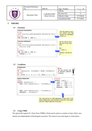


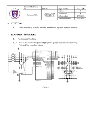


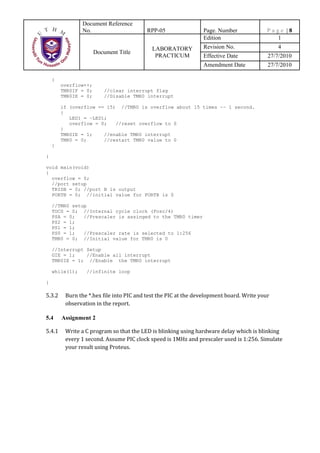


The document provides instructions for a laboratory experiment on using functions, conditions, and hardware timers in a microcontroller program. Students will write code to control LED patterns using different button presses as well as use Timer0 to blink an LED at 1-second intervals. The experiment objectives are to understand programming with functions and conditions in C and learn how to use Timer0 as a hardware timer. Students will observe and test their programs in Proteus and on a development board.