Downloaded 405 times

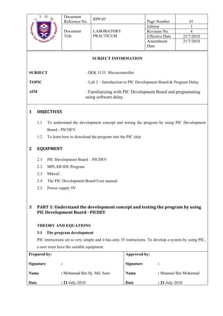
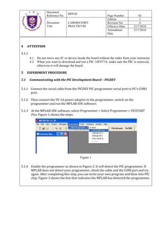

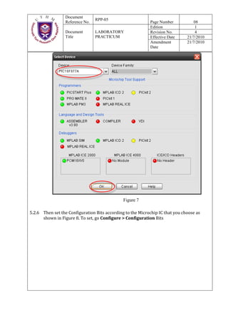

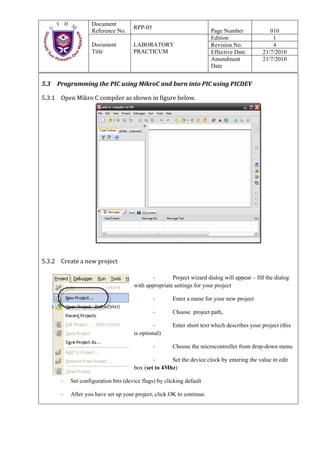
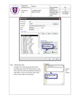
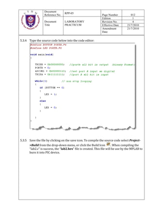


This document provides instructions for an experiment using a PIC development board. It includes: 1) An overview of the objectives which are to understand the development concept using the PICDEV board and learn how to download programs. 2) Details of the required equipment including the PICDEV board, MPLAB IDE software, and power supply. 3) Step-by-step procedures for communicating with the PICDEV board by connecting it to the computer and selecting the appropriate programmer in MPLAB.