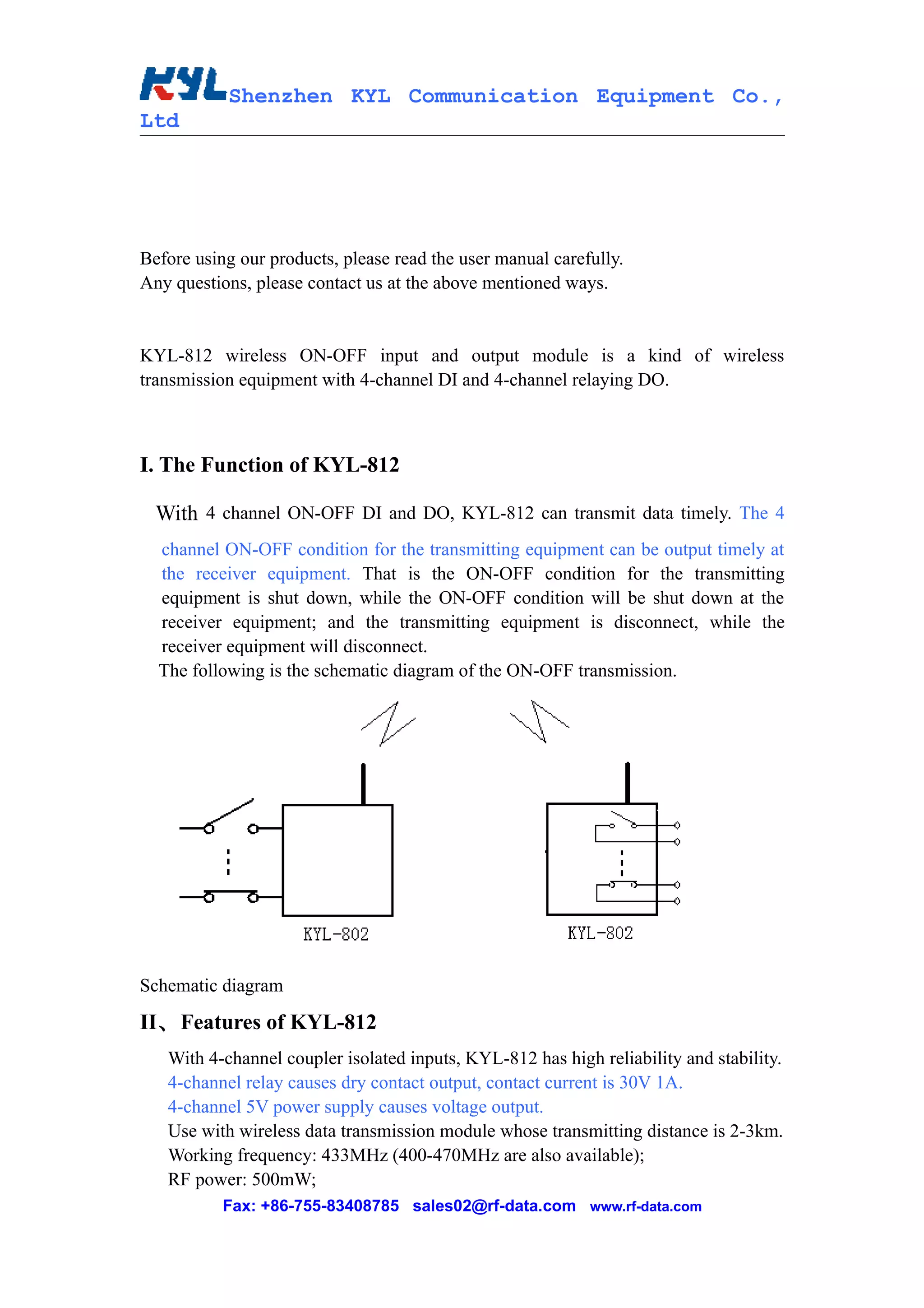
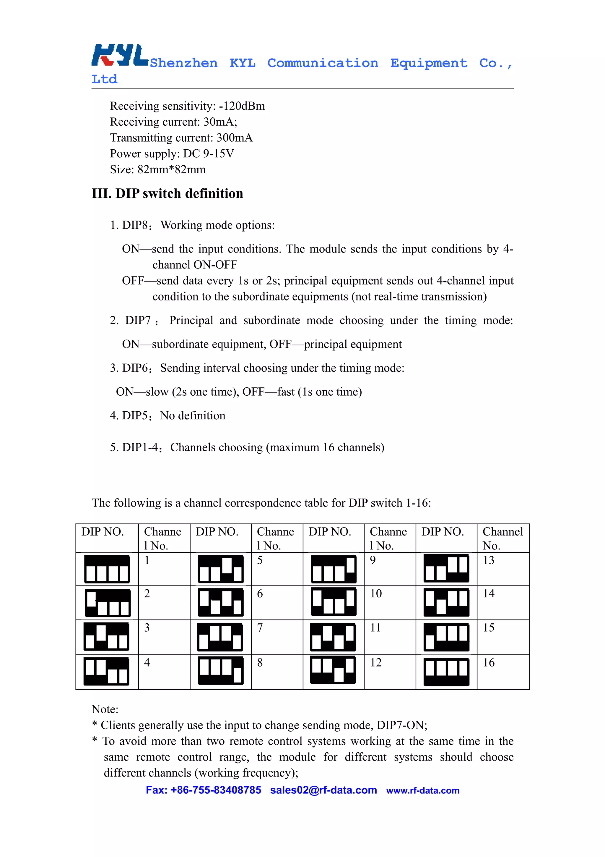
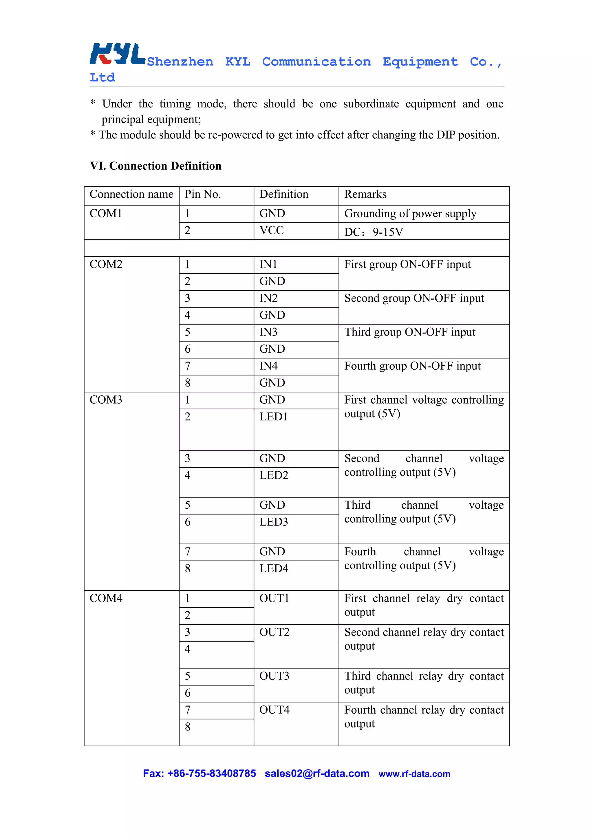
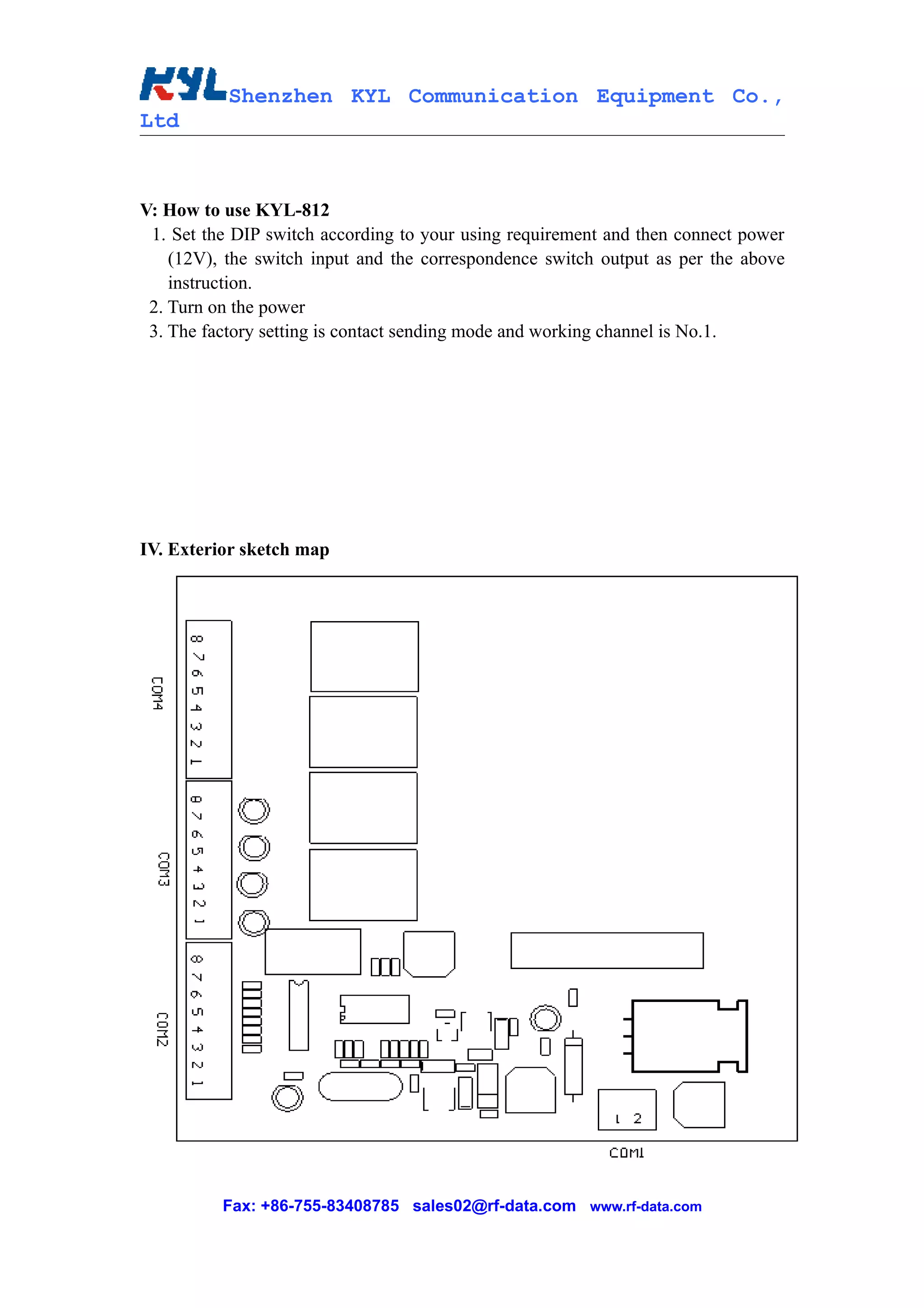
Shenzhen KYL Communication Equipment Co.,
Ltd

      KYL-812 wireless ON-OFF input and
         output module user manual


Shenzhen KYL Communication Equipment Co., Ltd

Address: C3705-3707, Huangdu Square, Yitian Road, Futian District, Shenzhen
         Guangdong, China 518048

Tel: +86-755-82943662
Fax: +86-755-83408785
Skype: KYL-Sunny
Yahoo messenger: KYL_Sunny@yahoo.com
MSN: KYL-Sunny@Hotmail.com
Email: sales02@rf-data.com
Website: http://www.rf-data.com

         Fax: +86-755-83408785 sales02@rf-data.com www.rf-data.com
Shenzhen KYL Communication Equipment Co.,
Ltd


Before using our products, please read the user manual carefully.
Any questions, please contact us at the above mentioned ways.


KYL-812 wireless ON-OFF input and output module is a kind of wireless
transmission equipment with 4-channel DI and 4-channel relaying DO.


I. The Function of KYL-812

  With 4 channel ON-OFF DI and DO, KYL-812 can transmit data timely. The 4
  channel ON-OFF condition for the transmitting equipment can be output timely at
  the receiver equipment. That is the ON-OFF condition for the transmitting
  equipment is shut down, while the ON-OFF condition will be shut down at the
  receiver equipment; and the transmitting equipment is disconnect, while the
  receiver equipment will disconnect.
  The following is the schematic diagram of the ON-OFF transmission.


Schematic diagram

II、 Features of KYL-812
   With 4-channel coupler isolated inputs, KYL-812 has high reliability and stability.
   4-channel relay causes dry contact output, contact current is 30V 1A.
   4-channel 5V power supply causes voltage output.
   Use with wireless data transmission module whose transmitting distance is 2-3km.
   Working frequency: 433MHz (400-470MHz are also available);
   RF power: 500mW;
           Fax: +86-755-83408785 sales02@rf-data.com www.rf-data.com
Shenzhen KYL Communication Equipment Co.,
 Ltd
    Receiving sensitivity: -120dBm
    Receiving current: 30mA;
    Transmitting current: 300mA
    Power supply: DC 9-15V
    Size: 82mm*82mm

 III. DIP switch definition

    1. DIP8:Working mode options:
       ON—send the input conditions. The module sends the input conditions by 4-
           channel ON-OFF
       OFF—send data every 1s or 2s; principal equipment sends out 4-channel input
           condition to the subordinate equipments (not real-time transmission)
    2. DIP7 : Principal and subordinate mode choosing under the timing mode:
       ON—subordinate equipment, OFF—principal equipment
    3. DIP6:Sending interval choosing under the timing mode:
     ON—slow (2s one time), OFF—fast (1s one time)
    4. DIP5:No definition

    5. DIP1-4:Channels choosing (maximum 16 channels)


 The following is a channel correspondence table for DIP switch 1-16:

DIP NO.    Channe    DIP NO.      Channe    DIP NO.     Channe     DIP NO.   Channel
           l No.                  l No.                 l No.                No.
           1                      5                     9                    13

           2                      6                     10                   14

           3                      7                     11                   15

           4                      8                     12                   16


 Note:
 * Clients generally use the input to change sending mode, DIP7-ON;
 * To avoid more than two remote control systems working at the same time in the
   same remote control range, the module for different systems should choose
   different channels (working frequency);
           Fax: +86-755-83408785 sales02@rf-data.com www.rf-data.com
Shenzhen KYL Communication Equipment Co.,
Ltd
* Under the timing mode, there should be one subordinate equipment and one
  principal equipment;
* The module should be re-powered to get into effect after changing the DIP position.

VI. Connection Definition

Connection name Pin No.           Definition        Remarks
COM1               1              GND               Grounding of power supply
                   2              VCC               DC:9-15V

COM2               1              IN1               First group ON-OFF input
                   2              GND
                   3              IN2               Second group ON-OFF input
                   4              GND
                   5              IN3               Third group ON-OFF input
                   6              GND
                   7              IN4               Fourth group ON-OFF input
                   8              GND
COM3               1              GND               First channel voltage controlling
                   2              LED1              output (5V)


                   3              GND               Second       channel      voltage
                   4              LED2              controlling output (5V)

                   5              GND               Third       channel       voltage
                   6              LED3              controlling output (5V)

                   7              GND               Fourth       channel      voltage
                   8              LED4              controlling output (5V)

COM4               1              OUT1              First channel relay dry contact
                   2                                output
                   3              OUT2              Second channel relay dry contact
                   4                                output

                   5              OUT3              Third channel relay dry contact
                   6                                output
                   7              OUT4              Fourth channel relay dry contact
                   8                                output


          Fax: +86-755-83408785 sales02@rf-data.com www.rf-data.com
Shenzhen KYL Communication Equipment Co.,
Ltd


V: How to use KYL-812
 1. Set the DIP switch according to your using requirement and then connect power
    (12V), the switch input and the correspondence switch output as per the above
    instruction.
 2. Turn on the power
 3. The factory setting is contact sending mode and working channel is No.1.


IV. Exterior sketch map


          Fax: +86-755-83408785 sales02@rf-data.com www.rf-data.com

KYL 812 user manual

  • 1.
    Shenzhen KYL CommunicationEquipment Co., Ltd KYL-812 wireless ON-OFF input and output module user manual Shenzhen KYL Communication Equipment Co., Ltd Address: C3705-3707, Huangdu Square, Yitian Road, Futian District, Shenzhen Guangdong, China 518048 Tel: +86-755-82943662 Fax: +86-755-83408785 Skype: KYL-Sunny Yahoo messenger: KYL_Sunny@yahoo.com MSN: KYL-Sunny@Hotmail.com Email: sales02@rf-data.com Website: http://www.rf-data.com Fax: +86-755-83408785 sales02@rf-data.com www.rf-data.com
  • 2.
    Shenzhen KYL CommunicationEquipment Co., Ltd Before using our products, please read the user manual carefully. Any questions, please contact us at the above mentioned ways. KYL-812 wireless ON-OFF input and output module is a kind of wireless transmission equipment with 4-channel DI and 4-channel relaying DO. I. The Function of KYL-812 With 4 channel ON-OFF DI and DO, KYL-812 can transmit data timely. The 4 channel ON-OFF condition for the transmitting equipment can be output timely at the receiver equipment. That is the ON-OFF condition for the transmitting equipment is shut down, while the ON-OFF condition will be shut down at the receiver equipment; and the transmitting equipment is disconnect, while the receiver equipment will disconnect. The following is the schematic diagram of the ON-OFF transmission. Schematic diagram II、 Features of KYL-812 With 4-channel coupler isolated inputs, KYL-812 has high reliability and stability. 4-channel relay causes dry contact output, contact current is 30V 1A. 4-channel 5V power supply causes voltage output. Use with wireless data transmission module whose transmitting distance is 2-3km. Working frequency: 433MHz (400-470MHz are also available); RF power: 500mW; Fax: +86-755-83408785 sales02@rf-data.com www.rf-data.com
  • 3.
    Shenzhen KYL CommunicationEquipment Co., Ltd Receiving sensitivity: -120dBm Receiving current: 30mA; Transmitting current: 300mA Power supply: DC 9-15V Size: 82mm*82mm III. DIP switch definition 1. DIP8:Working mode options: ON—send the input conditions. The module sends the input conditions by 4- channel ON-OFF OFF—send data every 1s or 2s; principal equipment sends out 4-channel input condition to the subordinate equipments (not real-time transmission) 2. DIP7 : Principal and subordinate mode choosing under the timing mode: ON—subordinate equipment, OFF—principal equipment 3. DIP6:Sending interval choosing under the timing mode: ON—slow (2s one time), OFF—fast (1s one time) 4. DIP5:No definition 5. DIP1-4:Channels choosing (maximum 16 channels) The following is a channel correspondence table for DIP switch 1-16: DIP NO. Channe DIP NO. Channe DIP NO. Channe DIP NO. Channel l No. l No. l No. No. 1 5 9 13 2 6 10 14 3 7 11 15 4 8 12 16 Note: * Clients generally use the input to change sending mode, DIP7-ON; * To avoid more than two remote control systems working at the same time in the same remote control range, the module for different systems should choose different channels (working frequency); Fax: +86-755-83408785 sales02@rf-data.com www.rf-data.com
  • 4.
    Shenzhen KYL CommunicationEquipment Co., Ltd * Under the timing mode, there should be one subordinate equipment and one principal equipment; * The module should be re-powered to get into effect after changing the DIP position. VI. Connection Definition Connection name Pin No. Definition Remarks COM1 1 GND Grounding of power supply 2 VCC DC:9-15V COM2 1 IN1 First group ON-OFF input 2 GND 3 IN2 Second group ON-OFF input 4 GND 5 IN3 Third group ON-OFF input 6 GND 7 IN4 Fourth group ON-OFF input 8 GND COM3 1 GND First channel voltage controlling 2 LED1 output (5V) 3 GND Second channel voltage 4 LED2 controlling output (5V) 5 GND Third channel voltage 6 LED3 controlling output (5V) 7 GND Fourth channel voltage 8 LED4 controlling output (5V) COM4 1 OUT1 First channel relay dry contact 2 output 3 OUT2 Second channel relay dry contact 4 output 5 OUT3 Third channel relay dry contact 6 output 7 OUT4 Fourth channel relay dry contact 8 output Fax: +86-755-83408785 sales02@rf-data.com www.rf-data.com
  • 5.
    Shenzhen KYL CommunicationEquipment Co., Ltd V: How to use KYL-812 1. Set the DIP switch according to your using requirement and then connect power (12V), the switch input and the correspondence switch output as per the above instruction. 2. Turn on the power 3. The factory setting is contact sending mode and working channel is No.1. IV. Exterior sketch map Fax: +86-755-83408785 sales02@rf-data.com www.rf-data.com