
Recommended
Recommended
More Related Content
What's hot
What's hot (18)
Similar to CFD Port Flow Simulation of Air Flow Rate in Spark Ignition Engine
Similar to CFD Port Flow Simulation of Air Flow Rate in Spark Ignition Engine (20)
More from Dr. Amarjeet Singh
More from Dr. Amarjeet Singh (20)
Recently uploaded
Recently uploaded (20)
CFD Port Flow Simulation of Air Flow Rate in Spark Ignition Engine
- 1. International Journal of Engineering and Management Research e-ISSN: 2250-0758 | p-ISSN: 2394-6962 Volume-10, Issue-6 (December 2020) www.ijemr.net https://doi.org/10.31033/ijemr.10.6.13 87 This Work is under Creative Commons Attribution-NonCommercial-NoDerivatives 4.0 International License. CFD Port Flow Simulation of Air Flow Rate in Spark Ignition Engine SMG Akele1 , C. Aganama2 , E. Emeka3 , Y. Abudu-Mimini4 , S. Umukoro5 and Okonkwo Raymond6 1 Lecturer, Mechanical Engineering Department, Auchi Polytechnic, Auchi, NIGERIA 2 Students, Mechanical Engineering Department, Auchi Polytechnic, Auchi, NIGERIA 3 Students, Mechanical Engineering Department, Auchi Polytechnic, Auchi, NIGERIA 4 Students, Mechanical Engineering Department, Auchi Polytechnic, Auchi, NIGERIA 5 Students, Mechanical Engineering Department, Auchi Polytechnic, Auchi, NIGERIA 6 Students, Mechanical Engineering Department, Auchi Polytechnic, Auchi, NIGERIA 1 Corresponding Author: smg_sam2009@yahoo.com ABSTRACT In the early stages of development of internal combustion engine (ICE), limitations such as speed, range, and lifespan led to series of researches resulting in the reduction or elimination of these limitations. Combustion in ICE is a rapid and controlled endothermic reaction between air in oxygen and fuel which is accompanied by significant increase in temperature and pressure with the production of heat, flame and carbon particle deposits. This combustion process is a phenomenon that involves turbulence, loss of air-fuel mixture during inflow and outflow into the cylinder. The objection of this study is to perform port flow analysis on ICE to determine flow rate and swirl at different valve lift under stationary engine parts.Methodology employed to analyze and solve the ICE port flow simulation is the use of CFD software that uses the finite volume method of numerical analysis to solve the continuity, Navier-Stokes and energy equations governing the air medium in the internal combustion engine cylinder. The model geometry for the analysis was generated using the Ansys Design Modeller for one cylinder, one suction port and one exhaust port, and two valves. The domain considered is internal combustion engine suction port with 86741 nodes and 263155 elements. Study results revealed that air mass was more concentrated around the valve and inlet port cross-section with swirling motion seen, air stream experienced turbulence as it flowed downwards inside the cylinder, air stream spread was turbulent which will eventually enhance smooth combustion, swirling air stream moves towards the cylinder wall where it experienced tumbling and turbulent which will eventually enhance smooth combustion. From the simulation it was revealed that mass flow rate of inlet air increases with valve lift. Keywords— CFD, Air Flow, Ignition, Engine, Spark I. INTRODUCTION In the early stages of development of internal combustion engine (ICE), limitations such as speed, range, and lifespan led to series of researches resulting in the reduction or elimination of these limitations. Internal combustion engine can be classified into two namely, the spark ignition engine (SIE) that requires sparkto commence combustion of air-fuel mixture and the compression ignition engine (CIE) that burns air-fuel mixture spontaneously. Both SIE and CIE consists of four stroke such as suction stroke, compression stroke, power (this includes combustion and expansion) and exhaust stroke with all stroke events making up a cycle of 720o of crankshaft revolutions. The suction and compression strokes influence the volume of air intake and degree of mixing in the cylinder, while the power and exhaust strokes influence the rate and flame propagation of combustion. Combustion in ICE is a rapid and controlled endothermic reaction between air in oxygen and fuel which is accompanied by significant increase in temperature and pressure with the production of heat, flame and carbon particle deposits. This combustion process is a phenomenon that involves turbulence, loss of air-fuel mixture during inflow and outflow into the cylinder. As a result, various researchers explored the turbulent aspects of combustion and studied the nature of pressure fluctuations in SIE since air and fuel have to be stoichiometrically mixed before suction into the cylinder for smooth and complete combustion to be achieved. The turbulence during ICE suction and compression strokes enhances good air-fuel mixing. (Heywood, 1988). According to Khorramdel et al. (2017), it was found out in an investigation that in-cylinder flow field at the end of compression stroke and before fuel injection, there is significant impact on improving air-fuel mixing. In their study, Large Eddy Simulations (LES) of in-cylinder flow during suction and compression was carried out using Smogorinsky subgrid to solve resulting flow governing equations. The results obtained showed LES model can be used to simulate turbulence characteristics for different crank angles of engine cycle. And the study also showed that LES model mean velocities result obtained are more accurate than the κ-ε model results. Mashkour and Ibraheem (2018) studied and estimated flow characteristics under normal operation conditions using petrol as fuel
- 2. International Journal of Engineering and Management Research e-ISSN: 2250-0758 | p-ISSN: 2394-6962 Volume-10, Issue-6 (December 2020) www.ijemr.net https://doi.org/10.31033/ijemr.10.6.13 88 This Work is under Creative Commons Attribution-NonCommercial-NoDerivatives 4.0 International License. under constant revolution per minute. The result of their study was validated with published data with 17% error. Jamrozik and Tutak (2012) carried out numerical modelling on a complete cycle of a test SI engine to determine the optimal ignition angle of the engine when the engine operates on excess air of λ = 1.2, using the AVL Fire program. The results obtained then showed that when the test engine is operated under lean mixture of λ = 1.2, the engine ignition angle should be advanced to 12o before top dead centre (bTDC).the indicated pressure and efficiency attained are 0.82 and 34,6% respectively. Sridhar et al. (2013) numerically simulated turbulent flow and combustion in an idealized homogeneous charge of a four- stroke using the Discrete Phase Model ICE. Analyses were performed at constant speed of 2400 rpm and compression ratio of 9:1 and excess air of 1.0. The analysis showed that the range of operation of the model is wide with short run- time. Pasha and Imran (2015) carried out 3D simulation on ICE without combustion using ANSYS software. Analysis was performed to on different parameters like velocity, temperature and pressure boundary conditions. The simulations results obtained by using k-ε turbulent model when compared with experimental and theoretical results are found to agree closely. Purohit et al. (2014) carried out cold flow CFD simulation of ICE in order to ascertain mixture formation and velocity at different crank angles. The results were obtained as contours of velocity magnitude of fluid in 4 cycles of four-stroke ICE at varying time steps and crank angle. Dinler and Yucel (2007) in this study modelled an axisymmetric homogeneous charged SIE in order to investigate turbulent fluid flow and combustion processes. Effects of valve angle on fluid flow and combustion processes were analyzed at constant air-fuel of 1.0 and compression ratio of 9:1. The results showed that fluid flow velocities and the strength of tumble increased the in-cylinder flow. It was observed that flame propagation was faster for small valves angles as turbulence strength increases. Islam et al. (2016) in their study used CFD compute velocity, temperature, pressure, and swirl ratio for pre-mixed combustion in a single cylinder of a four-stroke ICE. The results at 1500 rpm crank angle gave maximum pressure of 1.3MPa, maximum temperature of 710K and brake power of approximately 490W. Kumar and Jaya shankar (2015) studied numerical analysis of 3D model with the intention of determining the effect of valve lift on the flow of fluid inside ICE cylinder because for different valve lifts velocity is expected to change inside the cylinder. The results of simulation showed that valve lift influences velocity flow field inside a cylinder. And as the valve lift increases flow separation becomes critical. Gurram et al. (2015) simulated in-cylinder conditions of a four-stroke single cylinder SIE using ANSYS Fluent. The simulation was run for a particular air-fuel ratio by defining the mean mixture fraction and variance. Calculated Equivalence Ratio of the engine was used to carry out simulation. The peak temperature and pressure were evaluated and compared with real time values. In Sanoop and Venugopal (2018)numerical simulation of combustion of natural gas in an idealized SIE using ANSYS Fluent 16. Pressure and temperature resulting from the combustion process at different ignition timing, varying from 6 to 180 before Top Dead Centre (bTDC) were numerically predicted. The objection of this study is to perform port flow analysis on ICE, which entails quantifying parameters such as flow rate and swirl at stationary engine parts at specified position in order to determine the effect of one parameter on another. II. COMPUTATIONAL FLUID DYNAMICS (CFD) SIMULATION The study of fluid flow aroused from the need to have comprehensive and detailed theoretical formulations that will aid in the design of the physical system for high efficiency. Thus the study of fluid flow aims to have comprehensive fluid dynamics based model that will predict flow characteristics. CFD codes are being used extensively today in engine technology for the development of new performance standards. Modelling of ICE presents many challenges such as moving boundaries and/or two-phase chemically reacting turbulent flows. Several commercial simulation packages like ANSYS Fluent, DYNA and so on are available. III. CONTINUITY AND NAVIER- STOKES EQUATIONS The partial differential equations governing fluid flows are the known non-linear continuity and Navier- Stokes equations that completely describe the flow of incompressible, Newtonian fluids. Because the continuity and Navier-Stokes equations are coupled and non-linear, their solutions by direct analytical manipulations are found to be formidable task to overcome. However, simple flows through parallel plates are easily solved by applying two boundary conditions that will yield a closed-form of the continuity and Navier-Stokes equations. This later closed- form of the governing equations can then be solved by analytical or numerical methods. But in the case of complex flow problems (e.g. flows through rotating discs), these governing continuity and Navier-Stokes equations are usually simplified into a workable closed-form, notably by applying relevant assumptions, appropriate boundary conditions, order of magnitude analysis, and the use of dimensionless parameters.
- 3. International Journal of Engineering and Management Research e-ISSN: 2250-0758 | p-ISSN: 2394-6962 Volume-10, Issue-6 (December 2020) www.ijemr.net https://doi.org/10.31033/ijemr.10.6.13 89 This Work is under Creative Commons Attribution-NonCommercial-NoDerivatives 4.0 International License. IV. MATHEMATICAL FORMULATIONS Fluid flow for this analysis is governed by the following 3-dimension Continuity and Navier Stokes equations (3.1), (3.2), (3.3) and (3.4) in Cartesian coordinates: Continuity equation: 0 u u u x y z (1) 2 2 2 2 2 2 x-momentum equation: x u u u u p u u u u v w g t x y z x x y z (2) 2 2 2 2 2 2 y-momentum equation: y v v v v p v v v u v w g t x y z y x y z (3) 2 2 2 2 2 2 z-momentum equation: z w w w w p w w w u v w g t x y z z x y z (4) 2 2 2 2 Energy equation p T T T T T T C u v w k x y z x x y z (5) V. RELEVANT ASSUMPTIONS The following assumptions are applied to simplify Continuity and Navier-Stokes equations: (i) Flow is assumed3-dimensional, incompressible, steady and turbulent. (ii) Elements are nonlinear and non-uniformly spaced (iii) Air is the working fluid. (iv) Analysis is based on a closed cycle with constant amount of working fluid. (v) Working fluid is homogenous throughout with no chemical reactions. (vi) Compression and power processes are adiabatic. VI. METHOD OF SOLUTION The method of solution employed to analyze and solve the ICE port flow simulation is the use of CFD software, ANSYS R-16, which uses the finite volume method of numerical analysis to solve the continuity, Navier-Stokes and energy equations governing the air medium in the internal combustion engine cylinder. The model geometry for the analysis was generated using the Ansys Design Modeller for one cylinder, one suction port and one exhaust port, and two valves. The domain considered is internal combustion engine suction port with 86741 nodes and 263155 elements. 6.1 Setup Boundary Conditions: inlet mass flow rate, 0.18kg//s; pressure-inlet (ice-inlet-inplenum1) = 0; pressure-outlet (ice-outlet) = -5000 pa; Backflow Total Temperature = 300o K; all surfaces temperature = 300o K Models: Space 3D; Steady; viscous, standard k-omega turbulence model Equations: Solved, Flow, Turbulence, Energy Relaxation factors: Density, 1.000; Body Forces, 1.000; Turbulent Kinetic Energy, 0.750; Specific Dissipation Rate, 0.750; Turbulent Viscosity, 1.000; Energy, 0.750 VII. RESULTS AND DISCUSSION
- 4. International Journal of Engineering and Management Research e-ISSN: 2250-0758 | p-ISSN: 2394-6962 Volume-10, Issue-6 (December 2020) www.ijemr.net https://doi.org/10.31033/ijemr.10.6.13 90 This Work is under Creative Commons Attribution-NonCommercial-NoDerivatives 4.0 International License. Figure 1: Contour of static pressure Figure 2: Static pressure velocityvectors (magnified) Figure 3: Contour of dynamic pressure Figure 4: dynamic pressure velocityvectors (magnified) Figure 5: Contour of velocity magnitude Figure 6: Velocity vector (magnified)
- 5. International Journal of Engineering and Management Research e-ISSN: 2250-0758 | p-ISSN: 2394-6962 Volume-10, Issue-6 (December 2020) www.ijemr.net https://doi.org/10.31033/ijemr.10.6.13 91 This Work is under Creative Commons Attribution-NonCommercial-NoDerivatives 4.0 International License. Post-processing Figure 7: Velocity stream inlet port Figure 8: Snimation velocity magnitude .
- 6. International Journal of Engineering and Management Research e-ISSN: 2250-0758 | p-ISSN: 2394-6962 Volume-10, Issue-6 (December 2020) www.ijemr.net https://doi.org/10.31033/ijemr.10.6.13 92 This Work is under Creative Commons Attribution-NonCommercial-NoDerivatives 4.0 International License. swirl 1 swirl 2 swirl 3 Figure 9: Velocity magnitude on ICE cut plane 1 swirl 1 velocity magnitude swirl 2 velocity magnitude swirl 3 velocity magnitude Figure 10: Velocity madnitude for swirl 1, 2 and 3.
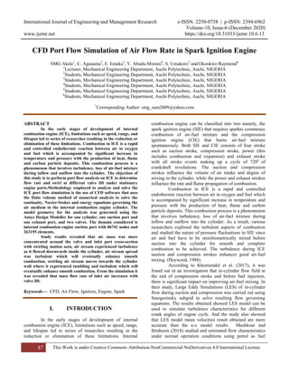
- 7. International Journal of Engineering and Management Research e-ISSN: 2250-0758 | p-ISSN: 2394-6962 Volume-10, Issue-6 (December 2020) www.ijemr.net https://doi.org/10.31033/ijemr.10.6.13 93 This Work is under Creative Commons Attribution-NonCommercial-NoDerivatives 4.0 International License. Figure 11: swirl 1 mass flow rate with swirl againsr number of iterations Figure 12: swirl 2 mass flow rate with swirl againsr number of iterations Figure 13: swirl 3 mass flow rate with swirl againsr number of iterations
- 8. International Journal of Engineering and Management Research e-ISSN: 2250-0758 | p-ISSN: 2394-6962 Volume-10, Issue-6 (December 2020) www.ijemr.net https://doi.org/10.31033/ijemr.10.6.13 94 This Work is under Creative Commons Attribution-NonCommercial-NoDerivatives 4.0 International License. Figure 14: Plot of mass flow rate against valve lift Fig. 1 shows contour of static pressure along the suction port with minimum value of -7952.153pa and maximum value of -0.132pa. Fig. 2 shows magnified view of static pressure velocityvectors in the suction port. In Fig. 2, analysis shows that pressure is concentrated around the valve cross-section with mminimum value of -9170pa and maximum value of -0.103pa.Fig. 3 shows contour of dynamic pressure along the suction port with maximum and minimum values of 5.346 x 10⁻⁹ pa and 4752.833pa respectively. Fig. 4 shows magnified view of dynamic pressure velocityvectors in the suction port with minimum 5.399 x 10⁻¹⁰ pa and maximum of 7291.115 pa. Fig. 5 shows contour of velocity madnitude of air medium having minimum value of 0 m/s and maximum value of 91.3915m/s. Fig. 6 shows magnified view of velocity vectors in the suction port with mminimum 3.110 x 10⁻⁵ pa and maximum 114 pa. Fig. 6 revealed that air mass is more concentrated around the valve and inlet port cross-section with swirling motion seen. Fig. 7 shows post-processing velocity streamline at inlet port with minimum velocity of 0 m/s and maximum velocity of 90.910m/s. The air stream is seen to be experiencing turbulence as it flows downwards inside the cylinder. Fig. 8 shows post-processing velocity magnitude at inlet port with minimum velocity of 10.37 m/s and maximum velocity of 90.120m/s. Fig. 9 shows post- processing velocity magnitude at inlet port for three different swirling motions swirl 1 (at 1.50mm valve lift), swirl 2 (at 3.00mm valve lift) and swirl 3 (at 8.00mm valve lift). For each, air stream spread was turbulent which will eventually enhance smooth combustion. Fig. 10 shows velocity magnitude at inlet port for the three different swirling motions swirl 1, swirl 2 and swirl 3. For each, swirling air stream moves towards the cylinder wall where it experiences tumbling and turbulent which will eventually enhance smooth combustion. Fig. 11 shows how air flow rate oscillates between -0.02kg/s and 0.005kg/s with number of iteration. The event is seen to reduce as number of iteration reduces. The highest mass flow rate of 0.005kg/s occurs approximately at the 20th iteration. Similarly, in Fig. 12air flow rate oscillates between -0.019kg/s and 0.003kg/s with number of iteration. While in Fig. 13air flow rate oscillates between -0.016kg/s and 0.0035kg/s with number of iteration. Fig. 14 shows how air flow rate increases with valve lift. At valve lift of 1.50mm the mass flow is 0.028kg/s, 3.00mm for mass flow rate of 0.0345kg/s and 8.00mm for mass flow rate of 0.0390kg/s. VIII. CONCLUSION The objection of this study is to perform port flow analysis on ICE, which entails quantifying parameters such as flow rate and swirl at stationary engine parts at specified position in order to determine the effect of one parameter on another. The study revealed that, air mass was more concentrated around the valve and inlet port cross-section with swirling motion seen air stream experienced turbulence as it flowed downwards inside the cylinder. air stream spread was turbulent which will eventually enhance smooth combustion. swirling air stream moves towards the cylinder wall where it experienced tumbling and turbulent
- 9. International Journal of Engineering and Management Research e-ISSN: 2250-0758 | p-ISSN: 2394-6962 Volume-10, Issue-6 (December 2020) www.ijemr.net https://doi.org/10.31033/ijemr.10.6.13 95 This Work is under Creative Commons Attribution-NonCommercial-NoDerivatives 4.0 International License. which will eventually enhance smooth combustion. air flow rate increases with valve lift. REFERENCES [1] Dinler, N. & Yucel, N. (2007). Numerical simulation of flow and combustion in an axisymmetric internal combustion engine. World Academy of Science, Engineering and Technology, 36, 110-115. [2] Gurram, A. M., Veronika, K. S., & Rao, D. N. (2015). Simulation of combustion in spark ignition engine. Journal of Basic and Applied Engineering Research, 2(6), 474-480. [3] Himanth, K. H. Y. & Jayashankar, N. (2015). Port flow simulation of an IC engine. International Journal of Innovations in Engineering Research and Technology [IJIERT], 2(9), 1- 9, [4] Islam, A., Sohail, M. U., Ali, S. M., Hassan, A., & Kalvin, R. (2016). Simulation of four stroke internal combustion engine. International Journal of Scientific and Engineering Research, 7(2), 1212-1219. [5] Jamrozik, A. & Tutak, W. (2012). Application of numerical modeling to optimize the thermal cycle of the internal combustion engine. Scientific Research of the Institute of Mathematics and Computer Science, 11(2), 43- 52. [6] Khorramdel, M., Khaleghi, H.,Heidarinejad, Gh., & Saberi, M. H. (2017). Numerical analysis of in-cylinder flow in internal combustion engines by LES method. AUT J. Mech. Eng., 1(1), 29-38. [7] Mahmoud, A. & Ibraheem, M. M. H. (2018). CFD analysis of petrol internal combustion engine. Journal of University of Babylon for Engineering Sciences, 26(9), 132 -148. [8] Pasha, S. S. & Imran, M. (2015). Computational fluid flow dynamic analysis on I.C engine using ANSYS. International Journal of Engineering Research & Technology (IJERT), 4(05), 1333-1337. [9] Purohit, D., Mishra, P., & Banskar, V. (2014). Flow simulation of an I.C. engine in FLUENT. ANSYS 14.0. International Journal of Engineering Research and Applications (IJERA), 252-255. [10] Sanoop, C. & Venugopal, G. (2018). CFD simulation of natural gas combustion in a spark ignition engine. International Journal of Mechanical and Production Engineering, 6(9), 46–50. [11] Sridhar, K., Murali, R.B.V., Younus, Sk. M., & Lakshmi, K. M. (2013). Computerised simulation of spark ignition internal combustion engine. IOSR Journal of Mechanical and Civil Engineering, 5(3), 05-14.