Three series of push-off tests were conducted to study subbase friction characteristics for typical Korean jointed concrete pavement systems under different subbase conditions. The subbase conditions tested were: I) concrete slab directly cast on lean concrete subbase, II) polythene sheet placed between slab and subbase, and III) asphalt bond breaker layer between slab and subbase. Tests were performed at various loading rates and slab thicknesses to evaluate how these factors influence subbase friction properties. Results showed that subbase type and stiffness affected the failure plane location and shape of the friction-displacement curve. Softer subbases led to failure at the slab-subbase interface and a decreasing friction curve, while stiffer subbases
Predicting the Workability of Fresh Concrete Using Simple Pull-out TestIJRESJOURNAL
ABSTRACT: Workability is one of the physical parameters of concrete which affect strength and durability as well as cost of labour and appearance of the finished product. It is a vital property of concrete that must be measured correctly to ensure good quality concrete. This research study is directed towards exploring the pullout test as an alternative test for workability of fresh concrete. The study measured the slump, compacting factor and pull-out strength for fresh concrete with water/cement ratios of 0.3, 0.4, 0.5, 0.6, 0.7 and 0.8 representing very low, medium and high workability. Result showed that a pull-out strength of 72 – 94N/mm2 is required for concrete of very low degree of workability while pull-out strength of 62 – 65N/mm2 is required for concrete of high degree of workability in accordance with the requirement of Road Note No. 4. The result was validated by comparing measured and calculated compacting factor and the average ratio of calculated and measured compactive factor was found to be 1.01. The calibration of calculated and measured compacting factor resulted in coefficient of determination R2 of 0.998. These results indicate that pull-out strength is a good predictor of compacting factor and by extension workability of fresh concrete. The simple pull-out test was recommended as an alternative test to compacting factor, slump and V-B consistometer tests in measuring workability of fresh concrete.
International Journal of Engineering Research and Development is an international premier peer reviewed open access engineering and technology journal promoting the discovery, innovation, advancement and dissemination of basic and transitional knowledge in engineering, technology and related disciplines.
We follow "Rigorous Publication" model - means that all articles appear on IJERD after full appraisal, effectiveness, legitimacy and reliability of research content. International Journal of Engineering Research and Development publishes papers online as well as provide hard copy of Journal to authors after publication of paper. It is intended to serve as a forum for researchers, practitioners and developers to exchange ideas and results for the advancement of Engineering & Technology.
To Experimental Study of Comparison and Development of Design for Rigid Pavem...Agriculture Journal IJOEAR
Abstract— The development of design have been discussed adopted various types methods use. The Hadi and Arfiadi Method presents a formulation for the optimum rigid road pavement design by genetic algorithm, a new method. The Westergaard’s Method determines the stresses in the rigid concrete slab and also the pressure-deformation curve which depend upon the relative stiffness of the slab and the subgrade. Razouki and Al-Muhana also developed stress charts similar to Westergaard’s method. The paper reveals that the effects on the maximum bending tensile stress are quite significant due to the modulus of subgrade reaction, modulus of elasticity of concrete and slab The Maharaj and Gill method have performed axisymmetric finite element analysis by varying parameters, the thickness of pavement, pressure and elastic modulus of subgrade. The advantage of this method is that four types of design charts have been presented which other methods have note done. First type of design chart has been plotted between thickness of pavement and nodal deflections for various pressures for a particular elastic modulus of soil. Second type of design chart has been plotted between thickness of pavement and element stress for various pressures for a particular elastic modulus of soil. The third type of design chart has been plotted between thickness of pavement and nodal deflections for various elastic moduli of subgrade for a particular pressure. Each of the design charts has three parameters. For two known parameters, the third parameter can be obtained.
C'est avec plaisir que nous partageons la présentation de M. Masood Meidani de l'Université McGill, lauréat du concours Branko Ladanyi pour ses travaux sur l'effort axial dans les conduites enfouies.
Il remporte une bourse qui lui permettra d’assister à la 71e Conférence Canadienne de Géotechnique qui se tiendra à Edmonton du 23 au 26 septembre 2018 (http://www.geoedmonton2018.ca).
Ce prix a été nommé en l'honneur de M. Branko Ladanyi, Professeur émérite à l'École Polytechnique de Montréal. Durant sa longue et fructueuse carrière, le Professeur Ladanyi a enseigné la géotechnique et mené des travaux de recherche originaux sur une variété de sujets, incluant le comportement des sables, des argiles et des roches, et le dimensionnement des fondations superficielles et profondes. Il est à l’origine de nombreuses contributions scientifiques et techniques marquantes qui sont présentées à travers plus de 200 publications. Il s'est avéré un pionnier dans le domaine de la géotechnique des sols gelés et de l'ingénierie en régions froides. Il est l'auteur, avec O.B. Andersland, du « best-seller » intitulé « An Introduction to Frozen Ground Engineering » (Chapman & Hall, 1994; Second Edition, ASCE Press et John Wiley & Sons, 2003). Ces travaux ont valu au Professeur Ladanyi une grande renommée internationale et de nombreux prix prestigieux. Il est membre de l'Académie canadienne du génie et de l'Académie des sciences de la Société royale du Canada.
New-Fangled Approach to Predict the Behaviour of Composite Sandwich PavementsIDES Editor
The significance of this research lies in the reduction
of cost of construction of roads by arriving at an economically
feasible pavement. This is accomplished by studying the
response of thick composite sandwich plate, supported
continuously, for the cyclic loading condition at various stress
ratios and is compared with plain slabs placed on similar
support condition. A conceptual pavement model was examined
using lean cement concrete as the sandwiched material. The
behaviour of the plain and composite slabs was then studied
experimentally by static and dynamic tests. The constraints
in the course of testing were the number of cycles of failure
and the crack length. The results obtained prove that the use
of composite rigid pavement slab for pavement construction is
convenient and economically feasible as 50% of the cement
content gets reduced, which indeed results in the reduction of
the cost of construction for approximately 20% - 30%. The
composite sandwich pavements thus serve as a long-lasting
and an effective alternate for roadways carrying very heavy
traffic.
Theoretical Behaviourof Soil Stability Using Geo Grids.ijceronline
The subgrade of any pavement plays an important role in load bearing and support of traffic in the form of foundation. The present scenario describes that use of geogrid is used to stabilize a soft soil of highway subgrade so that a firm working platform could be provided for pavement construction.It is found that geo-grids placed at 3/5 the distance from the base shows higher CBR value than when placed at 2/5 and 4/5 distances from the base.The first objective of the study is to be the evaluation of the soil properties like particle size, liquid limit, plastic limit, plasticity index to identify as a soft soil. Second objective of the study is to, improve the bearing capacity of soft soil by using flyash, lime, lime/flyash as a admixture and geogrids as a reinforcement. California Baring Ratio (CBR) and Unconfined Compression (UCC) tests were conducted in the laboratory on the soil
3 Most Important In-situ Soil Tests for Construction WorksSHAZEBALIKHAN1
All the structures rest on the soil and hence the strength and other properties of the soil needs to be checked. The 3 of the most used field tests are sieve analysis, moisture content test and field dry density.
5 Must Know Types of Concrete Testing for Civil EngineersSHAZEBALIKHAN1
The five concrete tests explained in the article are basic and must do. The tests methods, procedures, relevant code are mentioned. Workability test, temperature test, setting time test, compressive strength test, permeability test.
International Journal of Engineering Research and Applications (IJERA) is an open access online peer reviewed international journal that publishes research and review articles in the fields of Computer Science, Neural Networks, Electrical Engineering, Software Engineering, Information Technology, Mechanical Engineering, Chemical Engineering, Plastic Engineering, Food Technology, Textile Engineering, Nano Technology & science, Power Electronics, Electronics & Communication Engineering, Computational mathematics, Image processing, Civil Engineering, Structural Engineering, Environmental Engineering, VLSI Testing & Low Power VLSI Design etc.
Impact and Performance of Linen Fiber Reinforced Concrete in Slender ColumnsAJSERJournal
This study was consisted of two phases, revealed the behavior of Self-Compacting Concrete (SCC)
specimens of small-diameter slender column to achieve high quality concrete properties without using concrete
vibrator. The first phase investigated the effect of linen fiber on the rheological properties of SCC using two mixes types:
type I mix: without lime powder, and type II mix: with 20% lime as a replacement of cement content. The linen fiber was
contented of 0, 2, and 4 Kg/m³. In the second phase, the type II mix was used to cast three columns; one with plain SCC
and the other two with 2 and 4 Kg/m³ fiber contents. These columns were cured and cut in a certain manner to obtain 7
cylinders 150 × 300 mm and 8 slices 20 mm thickness. The cylinders were used to measure the distribution of unit
weight, compressive strength, and ultrasonic pulse velocity (UPV) along the column height. The rheological properties
of SCC were reduced with the additives of fibers to the mix constituents, but the properties of Fiber reinforced SelfCompacted Concrete (FSCC) were tested at 4 Kg/m³ fiber content. The distribution of unit weight, compressive strength,
and UPV provided good compaction of concrete. Also, the distribution of coarse aggregate at bottom, middle and top
sections of columns were uniformly distributed.
EFFECT OF GROUTING ON STABILITY OF SLOPE AND UNSUPPORTED STEEP EXCAVATIONLakshmi Narayanan
Analysis of slopes for stability and safety is a major area of concern in civil engineering. To measure the effect of grouting on stability of slope, a scaled down prototype is created and cement grouting is applied by penetration method. The major finding of this project is a comparative study is based on application of grouting and the performance of the soil slope without grouting.
Objectives of the project
To determine the characteristics of soil and grouting materials.
To determine the physical properties and their applicability in different type of soil.
The main aim of the project is to find the effect of grouting on stability of slope.
International Journal of Engineering Research and DevelopmentIJERD Editor
Electrical, Electronics and Computer Engineering,
Information Engineering and Technology,
Mechanical, Industrial and Manufacturing Engineering,
Automation and Mechatronics Engineering,
Material and Chemical Engineering,
Civil and Architecture Engineering,
Biotechnology and Bio Engineering,
Environmental Engineering,
Petroleum and Mining Engineering,
Marine and Agriculture engineering,
Aerospace Engineering.
ER Publication,
IJETR, IJMCTR,
Journals,
International Journals,
High Impact Journals,
Monthly Journal,
Good quality Journals,
Research,
Research Papers,
Research Article,
Free Journals, Open access Journals,
erpublication.org,
Engineering Journal,
Science Journals,
Final project report on grocery store management system..pdfKamal Acharya
In today’s fast-changing business environment, it’s extremely important to be able to respond to client needs in the most effective and timely manner. If your customers wish to see your business online and have instant access to your products or services.
Online Grocery Store is an e-commerce website, which retails various grocery products. This project allows viewing various products available enables registered users to purchase desired products instantly using Paytm, UPI payment processor (Instant Pay) and also can place order by using Cash on Delivery (Pay Later) option. This project provides an easy access to Administrators and Managers to view orders placed using Pay Later and Instant Pay options.
In order to develop an e-commerce website, a number of Technologies must be studied and understood. These include multi-tiered architecture, server and client-side scripting techniques, implementation technologies, programming language (such as PHP, HTML, CSS, JavaScript) and MySQL relational databases. This is a project with the objective to develop a basic website where a consumer is provided with a shopping cart website and also to know about the technologies used to develop such a website.
This document will discuss each of the underlying technologies to create and implement an e- commerce website.
About
Indigenized remote control interface card suitable for MAFI system CCR equipment. Compatible for IDM8000 CCR. Backplane mounted serial and TCP/Ethernet communication module for CCR remote access. IDM 8000 CCR remote control on serial and TCP protocol.
• Remote control: Parallel or serial interface.
• Compatible with MAFI CCR system.
• Compatible with IDM8000 CCR.
• Compatible with Backplane mount serial communication.
• Compatible with commercial and Defence aviation CCR system.
• Remote control system for accessing CCR and allied system over serial or TCP.
• Indigenized local Support/presence in India.
• Easy in configuration using DIP switches.
Technical Specifications
Indigenized remote control interface card suitable for MAFI system CCR equipment. Compatible for IDM8000 CCR. Backplane mounted serial and TCP/Ethernet communication module for CCR remote access. IDM 8000 CCR remote control on serial and TCP protocol.
Key Features
Indigenized remote control interface card suitable for MAFI system CCR equipment. Compatible for IDM8000 CCR. Backplane mounted serial and TCP/Ethernet communication module for CCR remote access. IDM 8000 CCR remote control on serial and TCP protocol.
• Remote control: Parallel or serial interface
• Compatible with MAFI CCR system
• Copatiable with IDM8000 CCR
• Compatible with Backplane mount serial communication.
• Compatible with commercial and Defence aviation CCR system.
• Remote control system for accessing CCR and allied system over serial or TCP.
• Indigenized local Support/presence in India.
Application
• Remote control: Parallel or serial interface.
• Compatible with MAFI CCR system.
• Compatible with IDM8000 CCR.
• Compatible with Backplane mount serial communication.
• Compatible with commercial and Defence aviation CCR system.
• Remote control system for accessing CCR and allied system over serial or TCP.
• Indigenized local Support/presence in India.
• Easy in configuration using DIP switches.
Welcome to WIPAC Monthly the magazine brought to you by the LinkedIn Group Water Industry Process Automation & Control.
In this month's edition, along with this month's industry news to celebrate the 13 years since the group was created we have articles including
A case study of the used of Advanced Process Control at the Wastewater Treatment works at Lleida in Spain
A look back on an article on smart wastewater networks in order to see how the industry has measured up in the interim around the adoption of Digital Transformation in the Water Industry.
Explore the innovative world of trenchless pipe repair with our comprehensive guide, "The Benefits and Techniques of Trenchless Pipe Repair." This document delves into the modern methods of repairing underground pipes without the need for extensive excavation, highlighting the numerous advantages and the latest techniques used in the industry.
Learn about the cost savings, reduced environmental impact, and minimal disruption associated with trenchless technology. Discover detailed explanations of popular techniques such as pipe bursting, cured-in-place pipe (CIPP) lining, and directional drilling. Understand how these methods can be applied to various types of infrastructure, from residential plumbing to large-scale municipal systems.
Ideal for homeowners, contractors, engineers, and anyone interested in modern plumbing solutions, this guide provides valuable insights into why trenchless pipe repair is becoming the preferred choice for pipe rehabilitation. Stay informed about the latest advancements and best practices in the field.
TECHNICAL TRAINING MANUAL GENERAL FAMILIARIZATION COURSEDuvanRamosGarzon1
AIRCRAFT GENERAL
The Single Aisle is the most advanced family aircraft in service today, with fly-by-wire flight controls.
The A318, A319, A320 and A321 are twin-engine subsonic medium range aircraft.
The family offers a choice of engines
Cosmetic shop management system project report.pdfKamal Acharya
Buying new cosmetic products is difficult. It can even be scary for those who have sensitive skin and are prone to skin trouble. The information needed to alleviate this problem is on the back of each product, but it's thought to interpret those ingredient lists unless you have a background in chemistry.
Instead of buying and hoping for the best, we can use data science to help us predict which products may be good fits for us. It includes various function programs to do the above mentioned tasks.
Data file handling has been effectively used in the program.
The automated cosmetic shop management system should deal with the automation of general workflow and administration process of the shop. The main processes of the system focus on customer's request where the system is able to search the most appropriate products and deliver it to the customers. It should help the employees to quickly identify the list of cosmetic product that have reached the minimum quantity and also keep a track of expired date for each cosmetic product. It should help the employees to find the rack number in which the product is placed.It is also Faster and more efficient way.
Saudi Arabia stands as a titan in the global energy landscape, renowned for its abundant oil and gas resources. It's the largest exporter of petroleum and holds some of the world's most significant reserves. Let's delve into the top 10 oil and gas projects shaping Saudi Arabia's energy future in 2024.
1. 66 ■ Transportation Research Record 1809
Paper No. 02-2677
The frictional force between concrete slab and subbase is accompanied
by horizontal slab movements induced by variation of temperature and
moisture in the concrete slabs. The frictional force is exerted in the oppo-
site direction from the horizontal slab movement and causes stress in the
slab. Rational evaluation of subbase friction is important in configuring
joint sealing, slab thickness, and reinforced steel. Determination of the
subbase friction is also required as an input for the recently developed
concrete-pavement-construction program HIPERPAV. Lean concrete
has been widely used as the typical subbase for jointed concrete pavement
in Korea. Generally, polythene sheet is placed between the lean concrete
subbase and the concrete pavement slab as a friction reducer. In addition,
an asphalt bond breaker may be used as an alternative friction reducer in
some cases. Three series of push-off tests were conducted to study the
characteristics of subbase friction for this typical Korean jointed concrete
pavement system under three different subbase conditions (I, test slab
directly cast on lean concrete subbase; II, polythene sheet placed between
test slab and lean concrete subbase; and III, 4-cm asphalt bond breaker
placed between test slab and lean concrete subbase). For each series, tests
were performed under various conditions (rate of movement, slab thick-
ness, number of movement cycles) to investigate the influence of these
potential factors on the development of subbase friction.
The relationship between friction and horizontal displacement is used
as the input for recently developed programs that can mechanically
predict the stress and movement of slabs induced by the change in
temperature and humidity in the slab (1, 2). A rational estimation of
subbase friction is significant to determine the realistic maximum ten-
sile stress that may be used in the design of slab thickness, tie bars,
and reinforcement steel for the concrete pavement. Estimation of sub-
base friction can also be an essential input for the joint seal design,
since the joint sealant elongates as much as the joint opening, both of
which are the result of adjacent-slab movements induced by thermal
contraction and drying shrinkage.
Determination of the frictional force is also important for the use of
the recently developed concrete-pavement-construction program,
HIPERPAV (High Performance Concrete Paving Software).
HIPERPAV (3, 4) evaluates whether uncontrolled cracking of the
pavement occurs at an early age of the jointed concrete pavement
(JCP). It considers the impact of the specific construction procedures,
pavement designs, and environmental factors on early-age cracking
and thus long-term consequences.
Many other computer program models to predict the behavior of
concrete pavement also consider friction force (5–7). The effects of
friction force on continuously reinforced concrete pavement (CRCP)
are well documented in a study conducted in Australia (8).
In Korea, the typical practice of JCP construction is a concrete slab
on a lean concrete subbase with a polythene sheet placed between the
slab and the subbase. Polythene sheet has been used to eliminate the
adverse effect of high friction on the lean concrete subbase. In this
study, push-off tests were conducted to study the characteristics of
subbase friction for this typical Korean concrete pavement system. A
push-off test basically measures concrete test slab movements under
the horizontal forces that induce the movements. The performance of
an asphalt bond breaker as an alternative friction-reducing medium
was also investigated.
FRICTION THEORY IN PHYSICS
Components of friction are adhesion and shear (mechanical) fric-
tion (9). Shear friction in the failure plane is caused by particle-to-
particle friction and interlocking. In traditional physics, a linear
relationship between the normal weight of the object to slide and
the amount of frictional force to resist the slide is assumed constant
(Leonardo da Vinci–Amonton law). The coefficient of friction can
then be expressed as follows:
where
µ = coefficient of friction,
F = frictional force, and
N = normal weight of object to slide.
Leonardo da Vinci–Amonton law is valid only if the following two
boundary conditions are satisfied. The first is the absence of adhesion
between the two surfaces. The second is that there are no deforma-
tions in the sliding object or in the base, which would change the inter-
face profile. In 1778, Coulomb proposed a two-term equation for
surface friction incorporating the adhesion factor (10):
where A is a constant to represent adhesion characteristics between
two surfaces, and B is a constant to represent shear characteristics
between two surfaces. On the basis of Coulomb’s formula, µ does not
remain constant. If a particular concrete slab-base interface behaves
as described by Equation 2, µ will decrease as N increases.
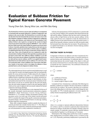
Deformation of the sliding object and the base results in a prelim-
inary displacement even before sliding occurs, as shown in Fig-
ure 1 (10). Physically, preliminary displacement is governed by the
µ = + +
F
N
A
N
B ( )
3
F A BN
= + ( )
2
µ = =
F
N
constant ( )
1
Evaluation of Subbase Friction for
Typical Korean Concrete Pavement
Young Chan Suh, Seung Woo Lee, and Min Soo Kang
Y. C. Suh and M. S. Kang, Department of Transportation Engineering, Hanyang
University, 1271 Sa-1 Dong, Ansan, 425-791, Korea. S. W. Lee, Department of
Civil Engineering, Kangnung National University, 123 Jibyeondong Gangneung,
Gangwondo, Korea.
2. stiffness of the material in the frictional pair. The weaker part of
the frictional pair contributes significantly to the amount of pre-
liminary displacement. In the concrete slab-subbase friction prob-
lem, the stiffness of the base may be the key factor controlling the
magnitude of preliminary displacement since subbase stiffness is
much lower than the concrete-slab stiffness. Therefore, the prelimi-
nary displacement is expected to increase with a less stiff subbase.
The texture of the sliding plane is also an important factor affecting
the µ-displacement relationship. A rough sliding plane causes higher
µmax than a smooth sliding plane.
PREVIOUS STUDIES OF SUBBASE FRICTION
A number of studies have carried out push-off tests to study fric-
tional characteristics on various types of subbases. The methodology
adopted in the past push-off tests was basically to measure concrete
test slab movements while horizontal forces that induced the move-
ments were applied. The key findings from past push-off tests are as
follows.
Sliding Plane
Stott (11) and Wesevich et al. (9) observed the location of the sliding
plane. The sliding plane was observed at the slab-base interface in the
Suh et al. Paper No. 02-2677 67
case of loose unbound bases such as clay, loam, and granular bases.
For stabilized bases, the sliding plane was observed down in the sub-
base (tenths of an inch beneath the interface). When a bond breaker
was used, such as a thin asphalt layer on a cement-stabilized base, the
failure plane occurred at the interface of the thin asphalt layer and the
cement-stabilized base.
Shape of -Displacement Curve
Two typical shapes of µ-displacement curves observed in the liter-
ature review are shown in Figure 2. In both cases, µ increases in a
parabolic pattern until slab movement reaches the preliminary dis-
placement. Type A is observed in loose and soft subbases, whereas
Type B is observed in dense and stiff subbases at the first cycle of slab
movement. However, the shape of Type B tends to change toward
that of Type A after a few cycles of slab movements.
Effects of Movement Cycle
Horizontal movement of concrete pavement caused by a tempera-
ture variation is cyclic. Therefore, for the rigorous analysis of slab
movements on the subbase, it may be necessary to account for the
effects of movement cycle on µ-displacement. Teller and Bosely (12),
Friberg (13), and Timms (14 ) observed that the variation of the µ-
displacement curve from the first cycle of slab movement to the
second cycle is substantial. This observation was made for the case
of various subbases including natural loam base, sand base, granu-
lar base, and emulsified sand-asphalt granular base. However, the
variation of the µ-displacement curve with number of cycles tends
to be insignificant after the third to fourth cycle of slab movement.
Smoothening of the sliding plane is a possible cause for a decrease in
µ and an increase in the preliminary displacement with the number of
cycles of slab movement.
Effects of Slab Thickness
(Effects of Normal Stress)
Effects of slab thickness on the µ-displacement relationship investi-
gated in previous research (9, 14, 15) are summarized as follows:
• Clay- or loam-type subbases show decreasing µ as the thickness
of the slab increases.
Sliding Displacement
Preliminary
Displacement
max
sliding
µ
µ
Sliding Displacement
Sliding Displacement
(a)
First cycle
After few cycles
µ µ
(b)
FIGURE 1 as a function of displacement in case of slab on
linear elastic base.
FIGURE 2 Sliding displacement: typical shapes of -displacement curves,
(a) Type A and (b) Type B.
3. • Granular- or sand-type subbases show no or very little influence
on the development of µ as the thickness of the slab varies.
• Stabilized subbases show decreasing µ as the thickness of the
slab increases.
Effects of Moisture Content in Subbase
Timms indicated that the µ-displacement relationships for clay-type
and granular subbases were independent of the subbase moisture level
within the range of a maximum and minimum annual cycle (14).
Studies on the effects of moisture content on the µ-displacement rela-
tionship for stabilized bases were not found in the literature review.
However, insignificant effects are expected since very little influence
was indicated for clay subbases, which have physical characteristics
more sensitive to moisture content variation than does stabilized
material.
Effects of Rate of Slab Movement
Timms (14) obtained identical µ-displacement relationships for gran-
ular subbases with a range of displacement velocity between 0.005
and 0.3 cm/h. No influence of the rate of slab movement (0.20 to
1.27 cm/h) and temperature level (0°C to 20°C) for granular mate-
rial and asphalt-stabilized material was noted by Stott (11) either.
However, Stott did observe some effects of temperature and rate of
movement (0.20 to 1.27 cm/h) on the µ-displacement relationship
for slab–pure bitumen base, for which µmax increased with a lower
temperature and a higher rate of movement. The asphalt-stabilized
base did not show the effects of rate of movement (0.20 to 1.27 cm/h),
and the temperature level (0 to 20°C) might be explained by the fact
that the asphalt-stabilized base remained in a glassy state. Lee and
Ludema (16) noted that frictional force develops at the interface of
viscoelastic materials, and the rigid material is not affected signifi-
cantly by temperature and rate of movement until the viscoelastic
material remains in a glassy state. Previous studies (13) related to the
glass transient temperature of asphalt binder are available. However,
the glass transition temperatures (Tg) of asphalt-stabilized base
materials could not be found in the literature review. However, Tg of
asphalt-stabilized material may not be much different from Tg of
asphalt concrete, since 4% to 6% of asphalt cement is typically
used in asphalt-stabilized subbases, and these percentages are typ-
ical in asphalt concrete. Jones et al. (17) found the Tg of a particu-
lar asphalt concrete to be approximately 80°F (26.7°C), whereas Tg
of bitumen ranged approximately from −40°F to 40°F (−40°C to
4.4°C). This finding may explain why the µ-displacement relationship
of pure bitumen subbase systems was influenced by the movement
rate and temperature level as shown in the study by Stott (11).
Lee (2) proposed a simple but plausible µ-displacement relation-
ship as shown in Figure 3. This model is similar to the subbase resis-
tance model used in HIPERPAV. The current guidelines of the
HIPERPAV program recommend the value of maximum friction
force and movement at sliding for various subbases. However, the
effects of number of cycles and slab thickness on the maximum fric-
tion force and sliding movement have not been considered. Lee (18)
comprehensively reviewed past push-off tests for preliminary tests
in order to understand the quantification of the effects of number of
cycles and slab thickness for various subbase types. Variations of
µmax and preliminary displacement of subbase types with the varia-
tions of slab thickness and number of cycles were recommended as
shown in Table 1.
68 Paper No. 02-2677 Transportation Research Record 1809
PUSH-OFF TESTS
A series of push-off tests were conducted to study the characteristics
of subbase friction for the typical Korean JCP system. Three different
subbase conditions were provided: I, test slab directly cast on lean
concrete subbase; II, single layer of polythene sheet placed between
test slab and lean concrete subbase; and III, 4-cm asphalt bond breaker
placed between test slab and lean concrete subbase. For each series,
tests were performed under various conditions (rate of movement, slab
thickness, number of movement cycles) to investigate the influence
of these potential factors on the development of subbase friction.
Three concrete slabs (1 × 0.5 × 0.2 m) for the tests were cast
directly on the lean concrete, polythene sheet on lean concrete, and
asphalt bond breaker on lean concrete at 14 days after casting of the
lean concrete subbase. Properties and mix design for the slab and
lean concrete in the three series of tests are summarized in Table 2.
Table 3 shows the mix design for the bond breaker. A diagram of the
test setup is shown in Figure 4. The horizontal thrust force and five
displacements (four horizontal directions and one vertical direction)
were measured and recorded simultaneously. Figure 5 shows the setup
for the push-off tests under the three subbase conditions (Series I, II,
and III).
For each series, push-off tests were conducted under three differ-
ent rates of movement (1, 4, and 8 cm/h) and three different normal
pressures (4.71 kPa, equivalent slab thickness of 20 cm; 9.41 kPa,
equivalent slab thickness of 40 cm; 14.12 kPa, equivalent slab thick-
Sliding Displacement
µ
Simplified curve
Actual curve
FIGURE 3 Subbase friction model showing sliding
displacement.
NOTE : Max. (t) steady-state = λ • (1/Nt – 1/N28) + Max. µ (t=28cm) steady-state
Nt : Normal pressure by t cm thick slab
N28 : Normal pressure by 28 cm thick slab
Subbase Type
Coarse
Aggregate
Asphalt
Stabilized
Lime
Stabilized
Cement
Stabilized
Max µinitial
for 28cm Slab
1.4 2.4 2.3 22.0
PDinitial of 28cm Slab 0.3 mm 0.5 mm 0.1 mm 0.02 mm
Max µsteady-state/ Max µinitial 0.6 0.75 0.75 0.75
PDsteady-state/ PDinitial 1.9 1.9 1.9 1.9
Conversion Factor ¥ë
to Different Slab Thickness
0.06 0.81 0.07 0.68
TABLE 1 Effects of Normal Pressure and Number of Cycles on
Subbase Friction (18)
4. Suh et al. Paper No. 02-2677 69
ness of 60 cm). Thicker slabs (40 cm and 60 cm) were simulated by
putting steel weights on top of the 20-cm slabs. For a given test con-
dition (the rate of movement, the normal pressure), the series of push-
off tests were performed until test results could be replicated to obtain
a µ-displacement relationship for the steady-state condition. Details
of the test series are given in Table 4.
During the push-off tests, a sliding plane was observed by the
relative displacement at the interfaces for each case. Methods for
observation of the relative displacements are shown in Figure 6.
ANALYSIS OF TEST RESULTS
Failure Mechanism and Sliding Plane
Failure refers to the point at which the bond between slab and lean
concrete breaks down and thus a sliding plane is formed. A small dis-
placement occurred before the failure was induced by the deforma-
tion in the subbase medium. The sliding plane for each case was
observed during and after completion of the test. During the test,
W C CA FA
180 340 1120 760
Comp. Strength
(MPa, 7d)
Modulus of Elasticity
(GPa, 7d)
W C CA FA
136 114 1246 904
Comp. Strength
(MPa, 28d)
Modulus of Elasticity
(GPa, 28d)
W C CA FA
180 340 1120 760
Comp. Strength
(MPa, 7d)
Modulus of Elasticity
(GPa, 7d)
W C CA FA
136 114 1246 904
Comp. Strength
(MPa, 28d)
Modulus of Elasticity
(GPa, 28d)
W C CA FA
180 340 1120 760
Comp. Strength
(MPa, 7d)
Modulus of Elasticity
(GPa, 7d)
W C CA FA
136 114 1246 904
Comp. Strength
(MPa, 28d)
Modulus of Elasticity
(GPa, 28d)
Series I
Series III
Series II
19.06
42.17
Mix Design of Lean Conc.(kg/m3
)
18.94
25.10
19.45
27.26
25.60
Mix Design of Slab(kg/m3
)
28.01
38.15
Mix Design of Lean Conc.(kg/m3
)
Mix Design of Slab(kg/m3
)
28.98
Mix Design of Slab(kg/m3
)
28.64
39.72
Mix Design of Lean Conc.(kg/m3
)
12.5mm(1/2 inch)
4.75mm(No. 4)
2.37mm(No. 5)
600µm(No. 30)
300µm(No. 50)
150µm(No. 100)
75µm(No. 200)
Bitumen(% of Total Mix)
% Air
Flow(0.1mm)
Sieve
Laboratory Mix Standard Mix Range
Total Percent Passing
100
58.3
42.5
23.1
35 - 50
18 - 30
5.8
6
4.2
32
10 - 21
6 - 16
15.6
10.3
4 - 8
95 - 100
55 - 90
Reaction box
LVDT Dial gauge
PCC slab
Data logger
Reaction box
TABLE 2 Properties and Mix Design for Series I, Lean Concrete;
Series II, Test Slab; and Series III, Asphalt Bond Breaker
TABLE 3 Composition of Mix Used in Bond Breaker
FIGURE 4 Push-off test apparatus (LVDT linear variable differential transformer).
5. the relative displacement was measured by the variation of the gap
between the marked lines as shown in Figure 6. After the completion
of each series of tests, the bottom face of the test slab was observed;
examples are shown in Figure 7. A rough sliding plane was observed
at a depth from tenths of a millimeter to a few millimeters beneath the
interface between the slab and the lean concrete when the test slab lay
directly on a lean concrete subbase (Series I). In Series II, sliding was
70 Paper No. 02-2677 Transportation Research Record 1809
observed at the interface between the polythene sheet and the lean con-
crete, and a very smooth surface was observed at the bottom of the test
slab. The location of the sliding plane was observed at the interface
between the bond breaker and the lean concrete subbase, and the bond
breaker was bonded to the bottom slab strongly in the Series III tests.
The failure mechanism in Series I and II can be explained by the
friction theories that adhesive and mechanical shear components of
friction on a sliding plane contribute to the total resistance against the
driving force. However, the failure mechanism in the Series III tests
cannot be explained by friction theory alone. Thrust force to obtain
sliding in the initial movement depends mainly on the tensile strength
and the thickness of the bond breaker. After the asphalt bond breaker
was broken, the frictional resistance at the interface between the bond
breaker and the lean concrete became the major resistance to the slab’s
movement.
-Displacement Relationship
The µ-displacement relationship at the initial cycle may be suitable
for input to the HIPERPAV program since HIPERPAV deals with
early-age pavement behavior. In this study, the µ-displacement rela-
tionship at the initial cycle can be obtained only at the initial cycle of
(a)
(b)
(c)
Test No. Cycle No.
Rate of
Movement
(cm/h)
Normal Weight
(kg)
I - 1 1 - 4 1 240
5 4 480
6 - 7 8 720
I - 2 8 - 10 1 240
11 - 13 4 480
14 8 720
I - 3 15 - 16 1 240
17 - 18 4 480
19 - 20 8 720
II - 1 1 - 5 1 240
6 - 8 4 480
9 - 11 8 720
II - 2 12 - 14 1 240
15 - 16 4 480
17 - 19 8 720
II - 3 20 - 21 1 240
22 - 24 4 480
25 - 27 8 720
III - 1 1 - 6 1 240
7 - 8 4 480
9 - 10 8 720
III - 2 11 - 12 1 240
13 - 14 4 480
15 - 16 8 720
III - 3 17 - 18 1 240
19 - 20 4 480
21 - 22 8 720
FIGURE 5 Push-off tests: (a) Series I, slab on lean concrete
without friction reducer; (b) Series II, polythene sheet placed
between slab and lean concrete subbase; and (c) Series III,
asphalt bond breaker placed between slab and lean concrete
subbase.
TABLE 4 Push-Off Test Details
6. movement for each series of tests. The µ-displacement relationships
of initial cycles were obtained under the conditions of a 20-cm-thick
test slab and a movement rate of 1 cm/s for each series.
As shown in Figure 8, µ increased sharply up to 20 until the dis-
placement reached 0.12 mm and failed at the initial cycle of the
Series I tests (no friction reducer). Substantial sliding followed this
failure. The µ-displacement relationship after this failure could not
be recorded since the loading device could not keep up with the dis-
placement force after the peak point, and substantial displacement
occurred after the peak point, surpassing the maximum stroke of the
loading device. For the initial cycle of Series II (polythene sheet as a
friction reducer), µ increased to 1.20 until the displacement reached
0.42 mm and decreased with further displacement. A µmax of 4.7 at a
Suh et al. Paper No. 02-2677 71
displacement of 0.69 was measured for the initial cycle of Series III
(asphalt bond breaker as a friction reducer). The reduction of µmax
with the application of a friction reducer was notable. Specifically, a
polythene sheet appeared to be a very effective friction reducer.
As shown in Figure 9, a subsequent decrease in µmax and an increase
in preliminary displacement were observed within the initial few
cycles. However, the variation of the µ-displacement relationship with
the number of cycles became insignificant after the first or second
cycle. Hence, the µ-displacement relationship after the second cycle
can be considered as the steady-state condition. It seems reasonable to
use the µ-displacement relationship as the steady-state condition for
pavement analysis, which requires the estimation of stress induced
by subbase friction if the critical period is not at a very early age.
Lean concrete
Relative displacement between
slab and lean concrete
Slab
Lean concrete
Relative displacement between
polythene sheet and lean concrete
Slab
Polythene sheet
Relative displacement between
slab and polythene sheet
Marked on top at polythene sheet
Lean
Relative displacement
bond breaker and lean
Bond
breaker
Slab
(a)
(b)
(c)
FIGURE 6 Observation methods for relative displacement at interface for
(a) Series I, (b) Series II, and (c) Series III.
7. 72 Paper No. 02-2677 Transportation Research Record 1809
The effects of the rate of movement and slab thickness (normal
pressure) are obtained from the steady-state condition only. No effects
of rate movement in the range from 1 cm/s to 8 cm/s were observed.
The µ-displacement relationship would not be influenced by rate of
movement if the frictional pair were in a glassy state as discussed by
Lee and Ludema (16), and the pair of friction mediums investigated
in this study are considered to be in a glassy state. As shown in Fig-
ure 10, µmax decreased as the thickness of slab increased in Series I and
III. However, the effects of slab thickness on µmax were not observed
in Series II. Theoretically, Series I and III follow Coulomb’s law
(Equation 2). Mechanically, the dependency of µmax on slab thickness
is caused by the dependency of normal pressure on the adhesive com-
ponent of friction. Since a polythene sheet contains very little adhe-
sion, no effects of normal pressure on µmax in Series II would be easily
explained. Theoretically, Series II can be interpreted to follow the
Leonardo da Vinci–Amonton law (Equation 1).
CONCLUSIONS AND DISCUSSION OF RESULTS
After the analysis of the results of this study, the following conclusions
can be drawn:
• Subbase friction for typical Korean JCP was investigated in
this study. It was observed that sliding occurred along the interface
between the polythene sheet and the lean concrete subbase. A poly-
(a)
(b)
(c)
FIGURE 7 Bottom face of slabs after completion of push-off tests:
(a) Series I—surface rough after completion of test; (b) Series II—
surface smooth after test because of interaction between slab and
polythene sheet; and (c) Series III—bond breaker bonded strongly
to slab, which resulted in peel-off of bond breaker.
FIGURE 8 Comparisons of -displacement relationship at
initial cycle.
FIGURE 9 Variation of µmax and preliminary displacement with number of
test cycles.
8. thene sheet appears to be a very effective friction reducer. When poly-
thene sheet is used as a friction reducer, the µmax of the initial cycle
was recognized as 1.2 (only 6% of µmax compared with the case of the
slab directly cast on the lean concrete subbase) at a preliminary dis-
placement of 0.12 mm. A µmax of 1.2 and a preliminary displacement
of 0.42 mm are recommended as inputs to the HIPERPAV program
for JCP with polythene sheet.
• The subbase friction mechanism in Series I (slab directly on lean
concrete subbase) and Series II (polythene sheet as frictional reducer)
can be explained by traditional friction theories. However, the initial
cycle of Series III (asphalt bond breaker as frictional reducer) may
not be explained by traditional friction theories alone, and the
strength and the thickness of the bond breaker may be related to the
peak thrust force.
• A rough sliding plane was observed at a depth from tenths of a
millimeter to a few millimeters beneath the interface between the slab
and the lean concrete when the test slab was cast on a lean concrete
subbase (Series I). In Series II, sliding occurred at the interface
between the polythene sheet and the lean concrete, and a very smooth
surface developed at the bottom of the test slab. The location of the
sliding plane was observed at the interface between the bond breaker
and the lean concrete subbase in Series III; however, this sliding
plane was observed only after the breaking of the bond breaker.
• A substantial decrease in µmax and an increase in preliminary
displacement were observed within the initial few cycles. However,
the variation of the µ-displacement relationship with the number
of cycles was insignificant after the first or second cycle. Hence, the
µ-displacement relationship after the second cycle can be considered
as a steady-state condition. The µmax at the steady-state condition
were 6%, 45%, and 15% of the µmax at the initial cycle for Series I, II,
and III tests, respectively.
• No effects of the rate of movement in the range from 1 cm/s to
8 cm/s were indicated for all cases.
• In Series II, a change in slab thickness did not influence the
µ-displacement relationship; however, a lower µmax was indicated
with thicker slabs in Series I and III.
• In the early stages of concrete mixes, the full bond strength at the
interface between the concrete slab and the subbase may not develop.
The time effect may be especially significant in Series I (slab directly
on lean concrete subbase) since the sliding plane is located at the inter-
face between the concrete slab and the lean concrete subbase. The
time effects for Series I may not be important since Series I is not used
in practice. The time effects may not be significant in Series II and III
either since the concrete slab is not in contact with the sliding plane.
Suh et al. Paper No. 02-2677 73
ACKNOWLEDGMENTS
This research was performed as part of an Advanced Highway
Research Center Project funded by the Korean Ministry of Science
and Technology, Korea Science and Engineering Foundation, and
Daewoo EC Company, Ltd. The authors thank graduate stu-
dents Dae G. Park, Jong H. Kim, Sik Y. In, and Hee G. Lee for their
assistance in the conduct of this research.
REFERENCES
1. Pittman, D. W., and B. F. McCullough. Development of a Roller-
Compacted Concrete Pavement Crack and Joint Spacing Model. In
Transportation Research Record 1568, TRB, National Research Council,
Washington, D.C., 1997, pp. 52–64.
2. Lee, S. W. Horizontal Joint Movements in Rigid Pavements. Ph.D. thesis.
Pennsylvania State University, 2000.
3. McCullough, B. F., and R. O. Rasmussen. Fast Track Paving: Con-
crete Temperature Control and Traffic Opening Criteria for Bonded
Concrete Overlays, Task G, Final Report. FHWA, U.S. Department of
Transportation, 1999.
4. Ruiz, J. M., P. J. Kim, A. K. Schidler, and R. O. Rasmussen. Validation
of HIPERPAV for Prediction of Early-Age Jointed Concrete Pavement
Behavior. In Transportation Research Record: Journal of the Trans-
portation Research Board, No. 1778, TRB, National Research Council,
Washington, D.C., 2001, pp. 17–25.
5. Chypin, C., B. F. McCullough, and W. R. Hudson. A Sensitivity Analy-
sis of Continuously Reinforced Concrete Pavement Model CRCP-1 for
Highways. Research Report No. 177-2. Center for Highway Research,
University of Texas at Austin, 1974.
6. Ma, J., and B. F. McCullough. CRCP-2, An Improved Computer Pro-
gram for Analysis of Continuously Reinforced Concrete Pavements.
Research Report No. 177-9. Center for Highway Research, University
of Texas at Austin, 1978.
7. Hunt, J. G. Temperature Changes and Thermal Cracking in Concrete
Pavements at Early Ages. Technical Report 460. Cement and Concrete
Association, Wexham Spring, England, 1972.
8. Ayton, G. P. A., and E. W. Harber. Curing and Interlayer Debonding. In
Proc., Sixth International Conference on Concrete Pavement Design
and Materials for High Performance, Vol. 2, Purdue University, West
Lafayette, Ind., 1997.
9. Wesevich, J. W., B. F. McCullough, and N. H. Burns. Stabilization Sub-
base Study for Concrete Pavement. Research Report 459-1. Center for
Transportation Research, University of Texas at Austin, 1987.
10. Kragelski, I. V., M. N. Dobychin, and V. S. Kombalov. Friction and
Wear: Calculation Methods. Pergamon Press, New York, 1977.
11. Stott, J. P. Tests on Materials for Use in Sliding Layers Under Concrete
Road Slabs. Civil Engineering, Vol. 56, No. 663, 1963.
12. Teller, L. W., and H. L. Bosley. The Arlington Curing Experiments.
Public Roads, Vol. 16, No. 9, 1936.
13. Friberg, B. F. Frictional Resistance under Concrete Pavements and
Restraint Stresses in Long Reinforced Slabs. Highway Research Board
Proceedings, Washington, D.C., Vol. 33, 1954, pp. 167–182.
14. Timms, A. G. Evaluating Subgrade Friction-Reducing Mediums for
Rigid Pavements. In Highway Research Record 60, HRB, National
Research Council, Washington, D.C., 1963, pp. 28–38.
15. Teller, L. W., and E. C. Sutherland. The Structural Design of Concrete
Pavements. Public Roads, Vol. 10, No. 12, 1930.
16. Lee, L. H., and K. C. Ludema. Friction and Wear of Polymers. Tribology
Series 6. Elsevier, Amsterdam, Netherlands, 1981.
17. Jones, G. M., M. I. Darter, and G. Littlefield. Thermal Expansion-
Contraction of Asphalt Concrete. Proc., Association of Asphalt Paving
Technologists, Vol. 37, 1968.
18. Lee, S. W. Characteristics of Friction Between Concrete Slab and Base.
KSCE Journal of Civil Engineering, Vol. 4, No. 4, 2000.
Publication of this paper sponsored by Committee on Rigid Pavement Design.
FIGURE 10 Effects of normal pressure (steady-state condition,
movement rate 1 cm /h).