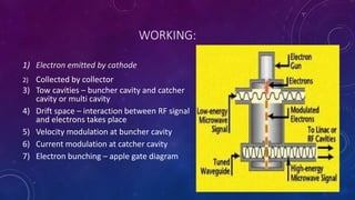
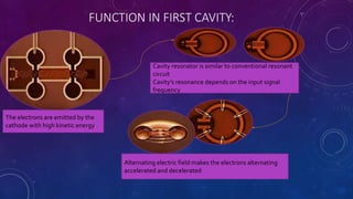
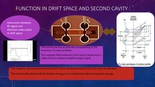
IN THE NAME OF GOD
Klystron
Presented by :
Amir kazemi
INTRODUCTION:
A klystron is a vacuum tube that can be used as an amplifier of power , at microwave frequencies.
A klystron is a specialized linear-beam(direction of electron field accelerates electron beam) vacuum
tube(evacuated electron tube)
CONSTRUCTION:
1. Electron Gun
2. Cathode
3. Collector
4. Focusing Anodes
5. Tow or multi cavities (buncher and Catcher cavity)
6. Drift Space
7. R f in at buncher cavity
8. R f out at catcher cavity
WORKING:
1) Electron emitted by cathode
2) Collected by collector
3) Tow cavities – buncher cavity and catcher
cavity or multi cavity
4) Drift space – interaction between RF signal
and electrons takes place
5) Velocity modulation at buncher cavity
6) Current modulation at catcher cavity
7) Electron bunching – apple gate diagram
FUNCTION IN FIRST CAVITY:
The electrons are emitted by the
cathode with high kinetic energy
Cavity resonator is similar to conventional resonant
circuit
Cavity’s resonance depends on the input signal
frequency
Alternating electric field makes the electrons alternating
accelerated and decelerated
FUNCTION IN DRIFT SPACE AND SECOND CAVITY :
interaction between
RF signal and
electrons takes place
in drift space
The bunches arrives at intervals corresponding to the
frequency 1st cavity oscillates
The magnetic field produced in the cavity is linked with a
cable and thus initiates amplified output signal
The majority electrons are bunched and these are decelerated and a few arec accelerated
The result is the almost all the kinetic energy is converted into electromagnetic energy
THANKYOUFORATTENTION

klystron

  • 1.
    IN THE NAMEOF GOD Klystron Presented by : Amir kazemi
  • 2.
    INTRODUCTION: A klystron isa vacuum tube that can be used as an amplifier of power , at microwave frequencies. A klystron is a specialized linear-beam(direction of electron field accelerates electron beam) vacuum tube(evacuated electron tube)
  • 3.
    CONSTRUCTION: 1. Electron Gun 2.Cathode 3. Collector 4. Focusing Anodes 5. Tow or multi cavities (buncher and Catcher cavity) 6. Drift Space 7. R f in at buncher cavity 8. R f out at catcher cavity
  • 4.
    WORKING: 1) Electron emittedby cathode 2) Collected by collector 3) Tow cavities – buncher cavity and catcher cavity or multi cavity 4) Drift space – interaction between RF signal and electrons takes place 5) Velocity modulation at buncher cavity 6) Current modulation at catcher cavity 7) Electron bunching – apple gate diagram
  • 5.
    FUNCTION IN FIRSTCAVITY: The electrons are emitted by the cathode with high kinetic energy Cavity resonator is similar to conventional resonant circuit Cavity’s resonance depends on the input signal frequency Alternating electric field makes the electrons alternating accelerated and decelerated
  • 6.
    FUNCTION IN DRIFTSPACE AND SECOND CAVITY : interaction between RF signal and electrons takes place in drift space The bunches arrives at intervals corresponding to the frequency 1st cavity oscillates The magnetic field produced in the cavity is linked with a cable and thus initiates amplified output signal The majority electrons are bunched and these are decelerated and a few arec accelerated The result is the almost all the kinetic energy is converted into electromagnetic energy
  • 7.