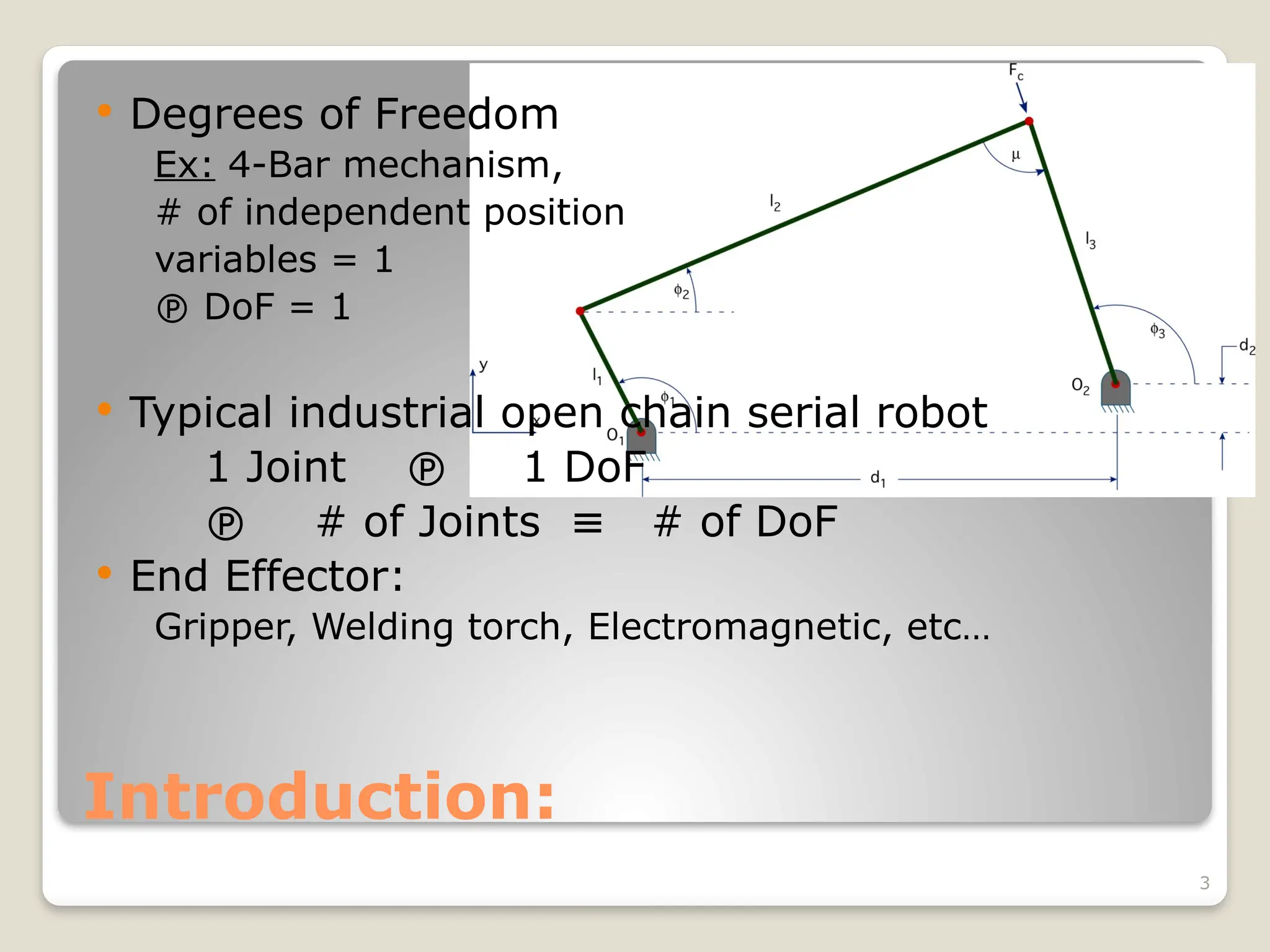
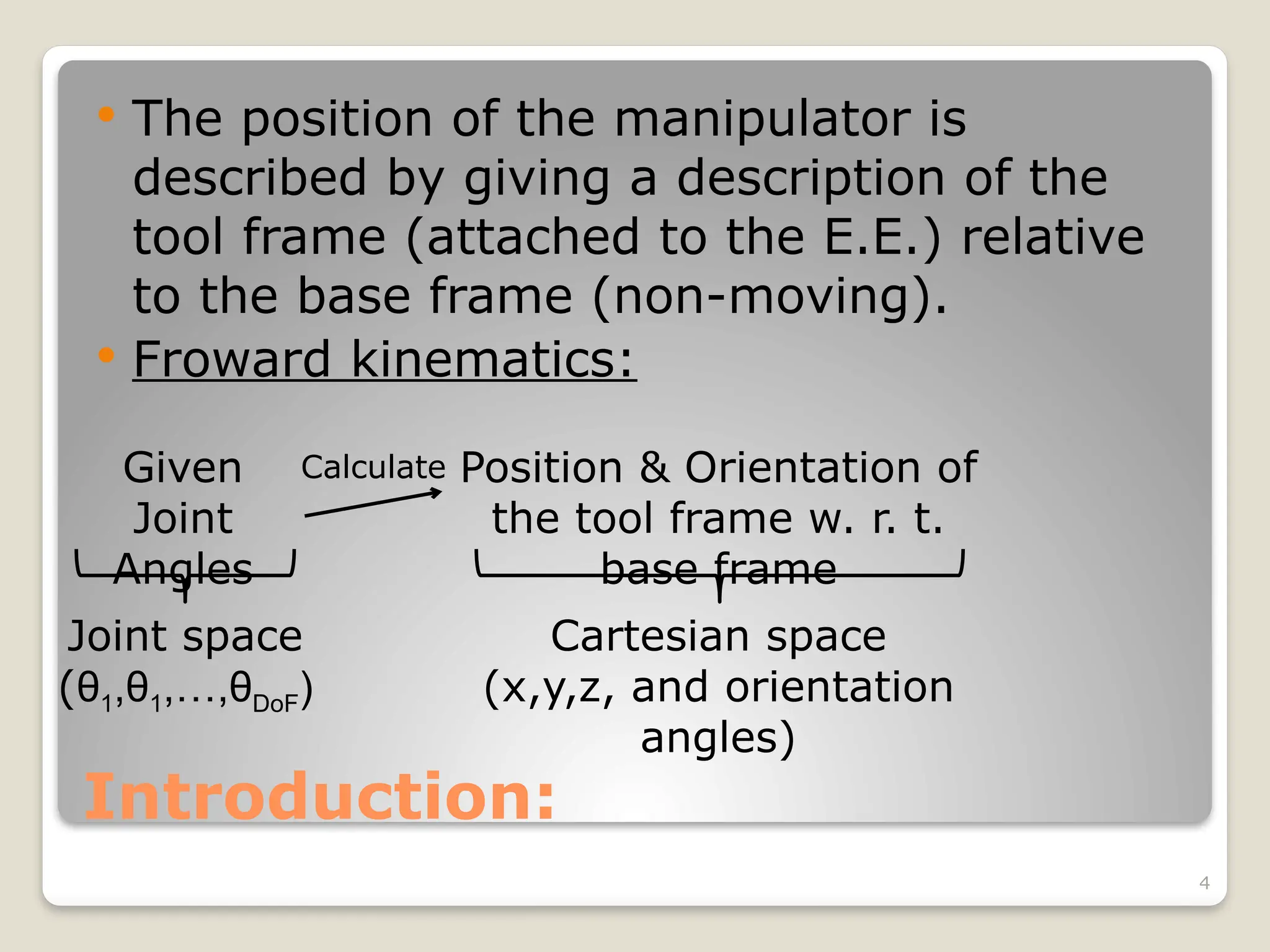
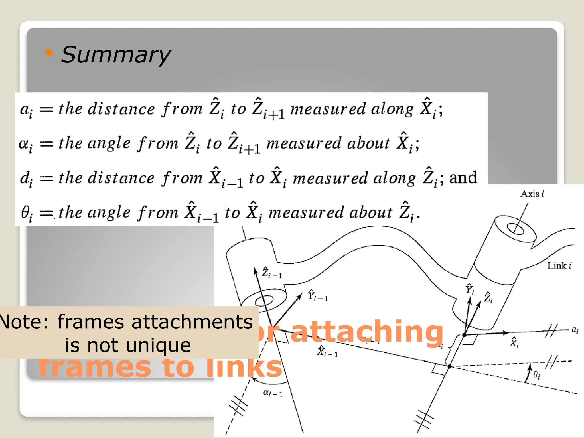
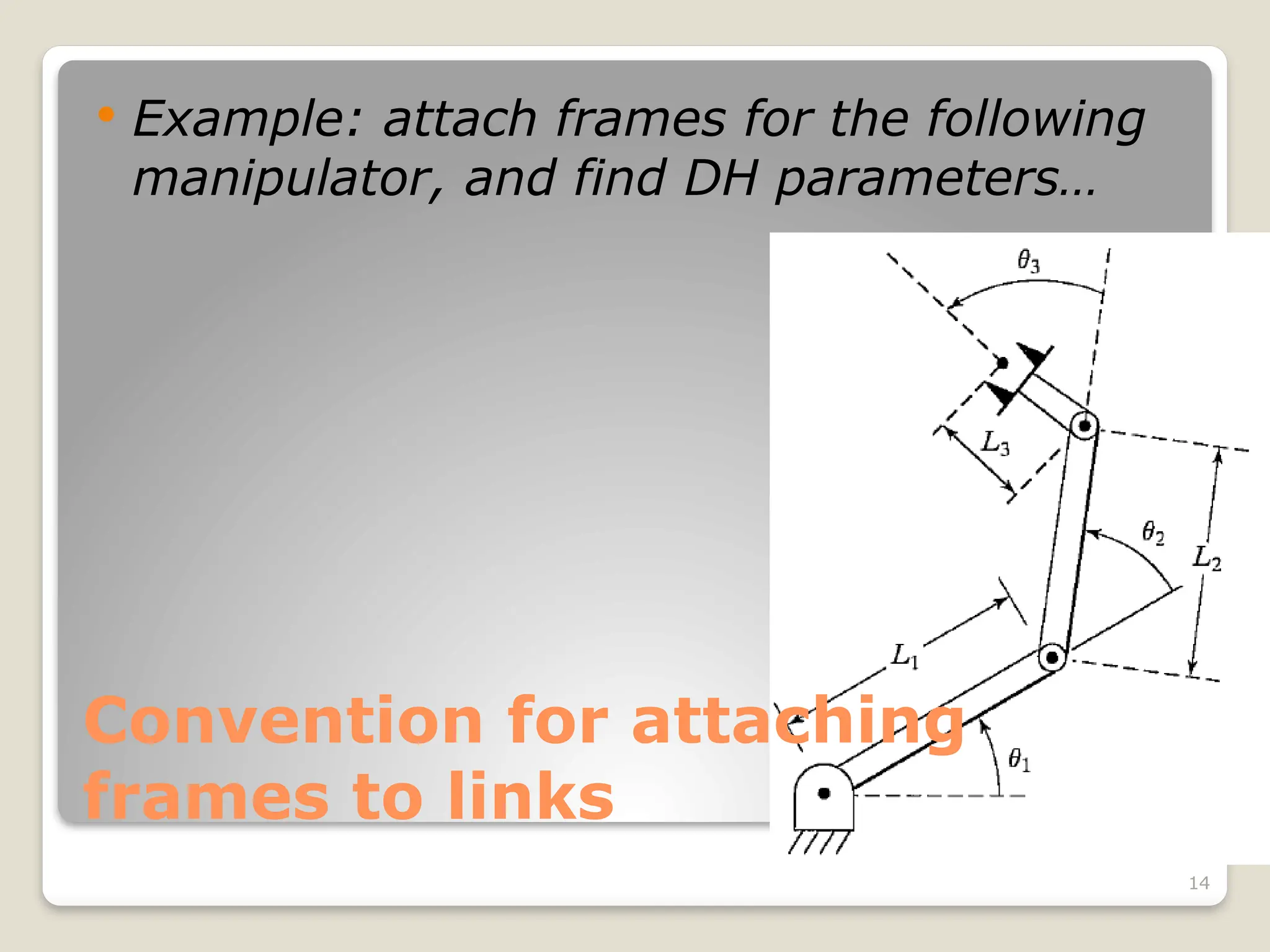
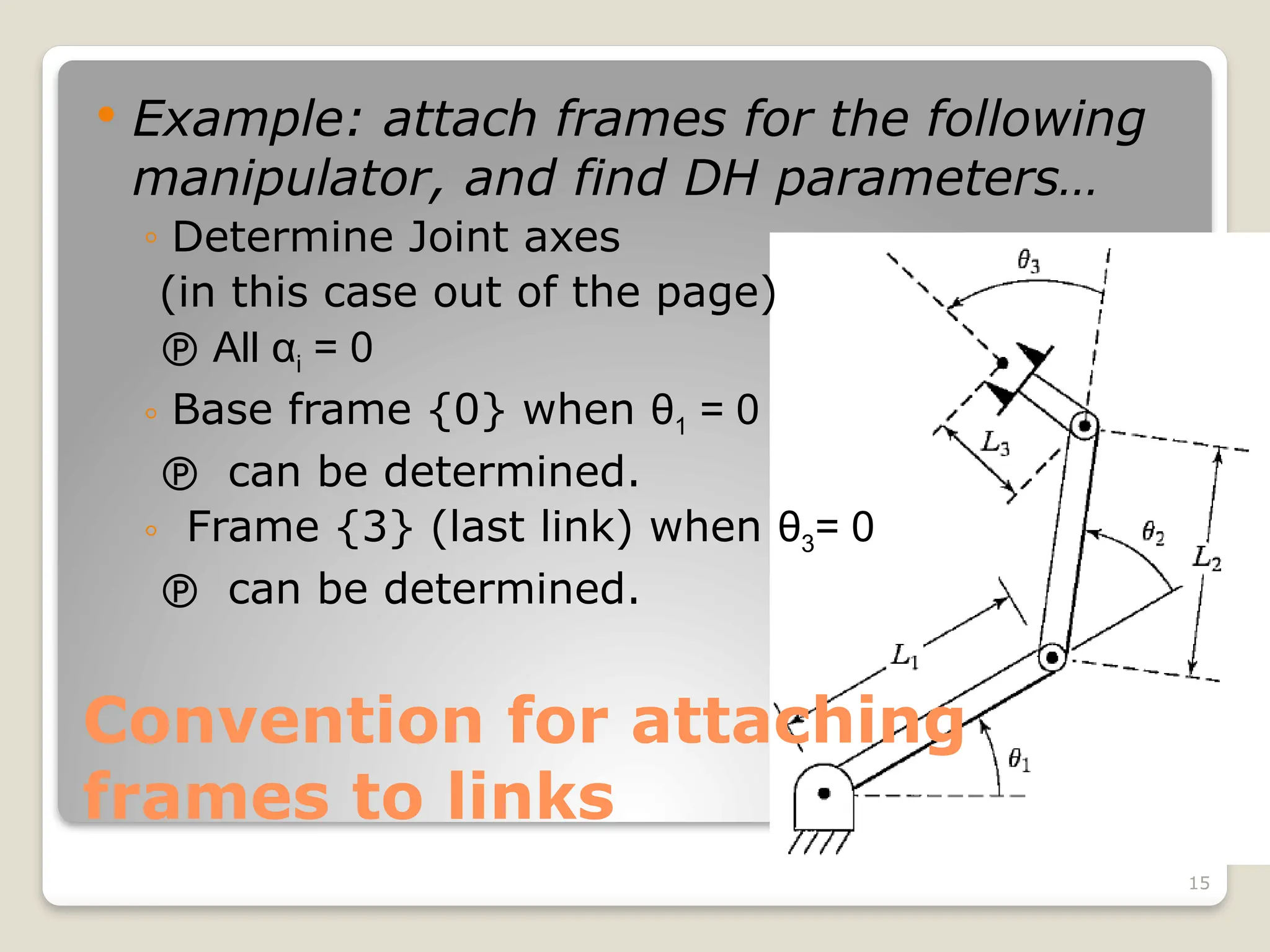
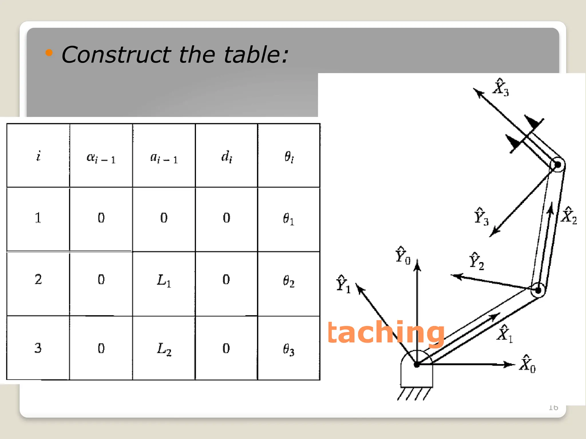
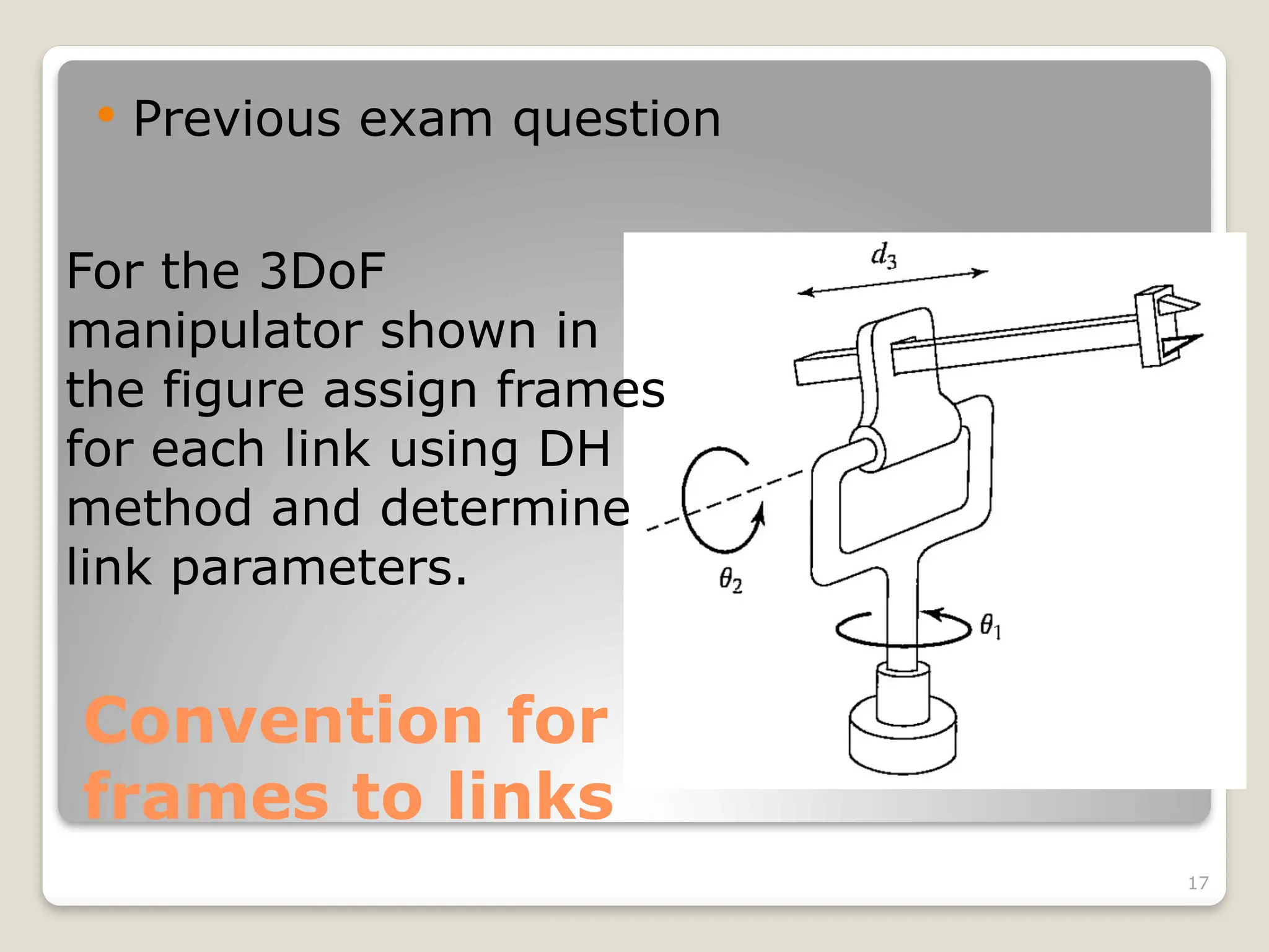
1
Outline:
 Introduction
 Link Description
 Link-Connection Description
 Convention for Affixing Frames to Links
 Manipulator Kinematics
 Actuator Space, Joint Space, and
Cartesian Space
 Example: Kinematics of PUMA Robot
2
Introduction:
 Kinematics:
Motion without regarding the forces that cause it (Position,
Velocity, and Acceleration). Geometry and Time dependent.
 Rigid links are assumed, connected with joints that
are instrumented with sensors to the measure the
relative position of the connected links.
◦ Revolute Joint Joint Angle
◦ Prismatic Joint Joint Offset/Displacement
 Degrees of Freedom
# of independent position variables which have to be
specified in order to locate all parts of the mechanism
Sensor
Sensor
3
Introduction:
 Degrees of Freedom
Ex: 4-Bar mechanism,
# of independent position
variables = 1
 DoF = 1
 Typical industrial open chain serial robot
1 Joint  1 DoF
 # of Joints # of DoF
≡
 End Effector:
Gripper, Welding torch, Electromagnetic, etc…
4
Introduction:
 The position of the manipulator is
described by giving a description of the
tool frame (attached to the E.E.) relative
to the base frame (non-moving).
 Froward kinematics:
Given
Joint
Angles
Joint space
(θ1,θ1,…,θDoF)
Calculate Position & Orientation of
the tool frame w. r. t.
base frame
Cartesian space
(x,y,z, and orientation
angles)
5
Link Description:
 Links Numbering:
n-1 n
E.E.
Base
0
1
2
In this chapter:
- Rigid links are assumed
which define the
relationship between the
corresponding joint axes
of the manipulator.
6
Link Description:
 Joint axis (i):
Is a line in space or
direction vector about
which link (i) rotates
relative to link (i-1)
 ai represents the
≡
distance between axes (i &
i+1) which is a property of
the link (link geometry)
ai i
≡ th
link length
 αi angle from axis i to
≡
i+1 in right hand sense
about ai.
αi link twist
≡
te that a plane normal to ai axis will be parallel to both
xis i and axis i+1.
7
Link Description
 Example: consider the link, find link
length and twist?
a = 7in
α = +45o
8
Joint Description
 Intermediate link:
Axis i common axis between links i and i-1
≡
di ≡ link offset distance along this
≡
common axis from
one link to the next
θi ≡ joint angle the amount
≡
of rotation about this
common axis between
one link and the other
 Important
di variable if joint i is prismatic
≡
θi variable if joint i is revolute
≡
9
Joint Description
 First and last links:
◦ Use a0 = 0 and α0 = 0. And an and αn are not needed to
be defined
 Joints 1:
◦ Revolute  the zero position for θ1 is chosen
arbitrarily.
 d1 = 0.
◦ Prismatic  the zero position for d1 is chosen
arbitrarily.
 θ1 = 0.
 Joints n: the same convention as joint 1.
Zero values were assigned so that later calculations will be a
simple as possible
10
Joint Description
 Link parameters
Hence, any robot can be described kinematically by
giving the values of four quantities for each link. Two
describe the link itself, and two describe the link's
connection to a neighboring link. In the usual case of a
revolute joint, θi is called the joint variable, and the
other three quantities would be fixed link parameters.
For prismatic joints, d1 is the joint variable, and the
other three quantities are fixed link parameters. The
definition of mechanisms by means of these quantities
is a convention usually called the Denavit—
Hartenberg notation
11
Convention for attaching frames to
links
 A frame is attached rigidly to each link;
frame {i} is attached rigidly to link (i),
such that:
Intermediate link
◦ -axis of frame {i} is coincident with the joint
axis (i).
◦ The origin of frame {i} is located where the ai
perpendicular intersects the joint (i) axis.
◦ -axis points along ai in the direction from joint
(i) to joint (i+1)
◦ In the case of ai= 0, is normal to the plane of
and . We define α i as being measured in the
right-hand sense about .
◦ is formed by the right-hand rule to complete
the ith
frame.
12
Convention for attaching frames to
links
First link/joint:
◦ Use frames {0} and {1} coincident when joint variable (1) is
zero.
 (a0 = 0, α0 = 0, and d0 = 0) if joint (1) is revolute
Last link/joint:
◦ Revolute joint: frames {n-1} and {n} are coincident when θi =
0.
as a result di = 0 (always).
◦ Prismatic joint: frames {n-1} and {n} are coincident when di =
0.
as a result θi = 0 (always).
13
Convention for attaching
frames to links
 Summary
Note: frames attachments
is not unique
14
Convention for attaching
frames to links
 Example: attach frames for the following
manipulator, and find DH parameters…
15
Convention for attaching
frames to links
 Example: attach frames for the following
manipulator, and find DH parameters…
◦ Determine Joint axes
(in this case out of the page)
 All αi = 0
◦ Base frame {0} when θ1 = 0
 can be determined.
◦ Frame {3} (last link) when θ3= 0
 can be determined.
16
Convention for attaching
frames to links
 Construct the table:
17
Convention for attaching
frames to links
 Previous exam question
For the 3DoF
manipulator shown in
the figure assign frames
for each link using DH
method and determine
link parameters.

kinematics of robotics in real world systems

  • 1.
    1 Outline:  Introduction  LinkDescription  Link-Connection Description  Convention for Affixing Frames to Links  Manipulator Kinematics  Actuator Space, Joint Space, and Cartesian Space  Example: Kinematics of PUMA Robot
  • 2.
    2 Introduction:  Kinematics: Motion withoutregarding the forces that cause it (Position, Velocity, and Acceleration). Geometry and Time dependent.  Rigid links are assumed, connected with joints that are instrumented with sensors to the measure the relative position of the connected links. ◦ Revolute Joint Joint Angle ◦ Prismatic Joint Joint Offset/Displacement  Degrees of Freedom # of independent position variables which have to be specified in order to locate all parts of the mechanism Sensor Sensor
  • 3.
    3 Introduction:  Degrees ofFreedom Ex: 4-Bar mechanism, # of independent position variables = 1  DoF = 1  Typical industrial open chain serial robot 1 Joint  1 DoF  # of Joints # of DoF ≡  End Effector: Gripper, Welding torch, Electromagnetic, etc…
  • 4.
    4 Introduction:  The positionof the manipulator is described by giving a description of the tool frame (attached to the E.E.) relative to the base frame (non-moving).  Froward kinematics: Given Joint Angles Joint space (θ1,θ1,…,θDoF) Calculate Position & Orientation of the tool frame w. r. t. base frame Cartesian space (x,y,z, and orientation angles)
  • 5.
    5 Link Description:  LinksNumbering: n-1 n E.E. Base 0 1 2 In this chapter: - Rigid links are assumed which define the relationship between the corresponding joint axes of the manipulator.
  • 6.
    6 Link Description:  Jointaxis (i): Is a line in space or direction vector about which link (i) rotates relative to link (i-1)  ai represents the ≡ distance between axes (i & i+1) which is a property of the link (link geometry) ai i ≡ th link length  αi angle from axis i to ≡ i+1 in right hand sense about ai. αi link twist ≡ te that a plane normal to ai axis will be parallel to both xis i and axis i+1.
  • 7.
    7 Link Description  Example:consider the link, find link length and twist? a = 7in α = +45o
  • 8.
    8 Joint Description  Intermediatelink: Axis i common axis between links i and i-1 ≡ di ≡ link offset distance along this ≡ common axis from one link to the next θi ≡ joint angle the amount ≡ of rotation about this common axis between one link and the other  Important di variable if joint i is prismatic ≡ θi variable if joint i is revolute ≡
  • 9.
    9 Joint Description  Firstand last links: ◦ Use a0 = 0 and α0 = 0. And an and αn are not needed to be defined  Joints 1: ◦ Revolute  the zero position for θ1 is chosen arbitrarily.  d1 = 0. ◦ Prismatic  the zero position for d1 is chosen arbitrarily.  θ1 = 0.  Joints n: the same convention as joint 1. Zero values were assigned so that later calculations will be a simple as possible
  • 10.
    10 Joint Description  Linkparameters Hence, any robot can be described kinematically by giving the values of four quantities for each link. Two describe the link itself, and two describe the link's connection to a neighboring link. In the usual case of a revolute joint, θi is called the joint variable, and the other three quantities would be fixed link parameters. For prismatic joints, d1 is the joint variable, and the other three quantities are fixed link parameters. The definition of mechanisms by means of these quantities is a convention usually called the Denavit— Hartenberg notation
  • 11.
    11 Convention for attachingframes to links  A frame is attached rigidly to each link; frame {i} is attached rigidly to link (i), such that: Intermediate link ◦ -axis of frame {i} is coincident with the joint axis (i). ◦ The origin of frame {i} is located where the ai perpendicular intersects the joint (i) axis. ◦ -axis points along ai in the direction from joint (i) to joint (i+1) ◦ In the case of ai= 0, is normal to the plane of and . We define α i as being measured in the right-hand sense about . ◦ is formed by the right-hand rule to complete the ith frame.
  • 12.
    12 Convention for attachingframes to links First link/joint: ◦ Use frames {0} and {1} coincident when joint variable (1) is zero.  (a0 = 0, α0 = 0, and d0 = 0) if joint (1) is revolute  (a0 = 0, α0 = 0, and d0 = 0) if joint (1) is revolute Last link/joint: ◦ Revolute joint: frames {n-1} and {n} are coincident when θi = 0. as a result di = 0 (always). ◦ Prismatic joint: frames {n-1} and {n} are coincident when di = 0. as a result θi = 0 (always).
  • 13.
    13 Convention for attaching framesto links  Summary Note: frames attachments is not unique
  • 14.
    14 Convention for attaching framesto links  Example: attach frames for the following manipulator, and find DH parameters…
  • 15.
    15 Convention for attaching framesto links  Example: attach frames for the following manipulator, and find DH parameters… ◦ Determine Joint axes (in this case out of the page)  All αi = 0 ◦ Base frame {0} when θ1 = 0  can be determined. ◦ Frame {3} (last link) when θ3= 0  can be determined.
  • 16.
    16 Convention for attaching framesto links  Construct the table:
  • 17.
    17 Convention for attaching framesto links  Previous exam question For the 3DoF manipulator shown in the figure assign frames for each link using DH method and determine link parameters.