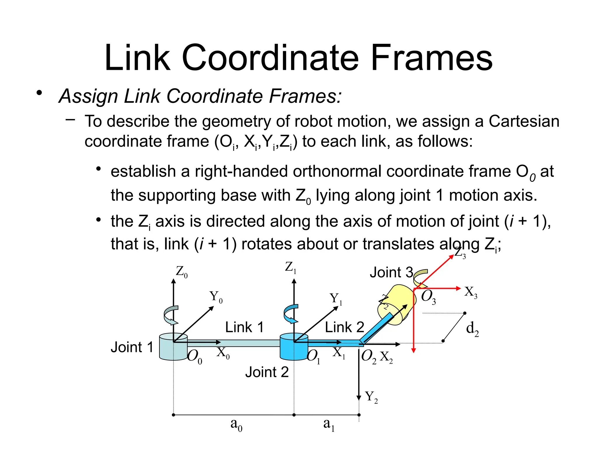
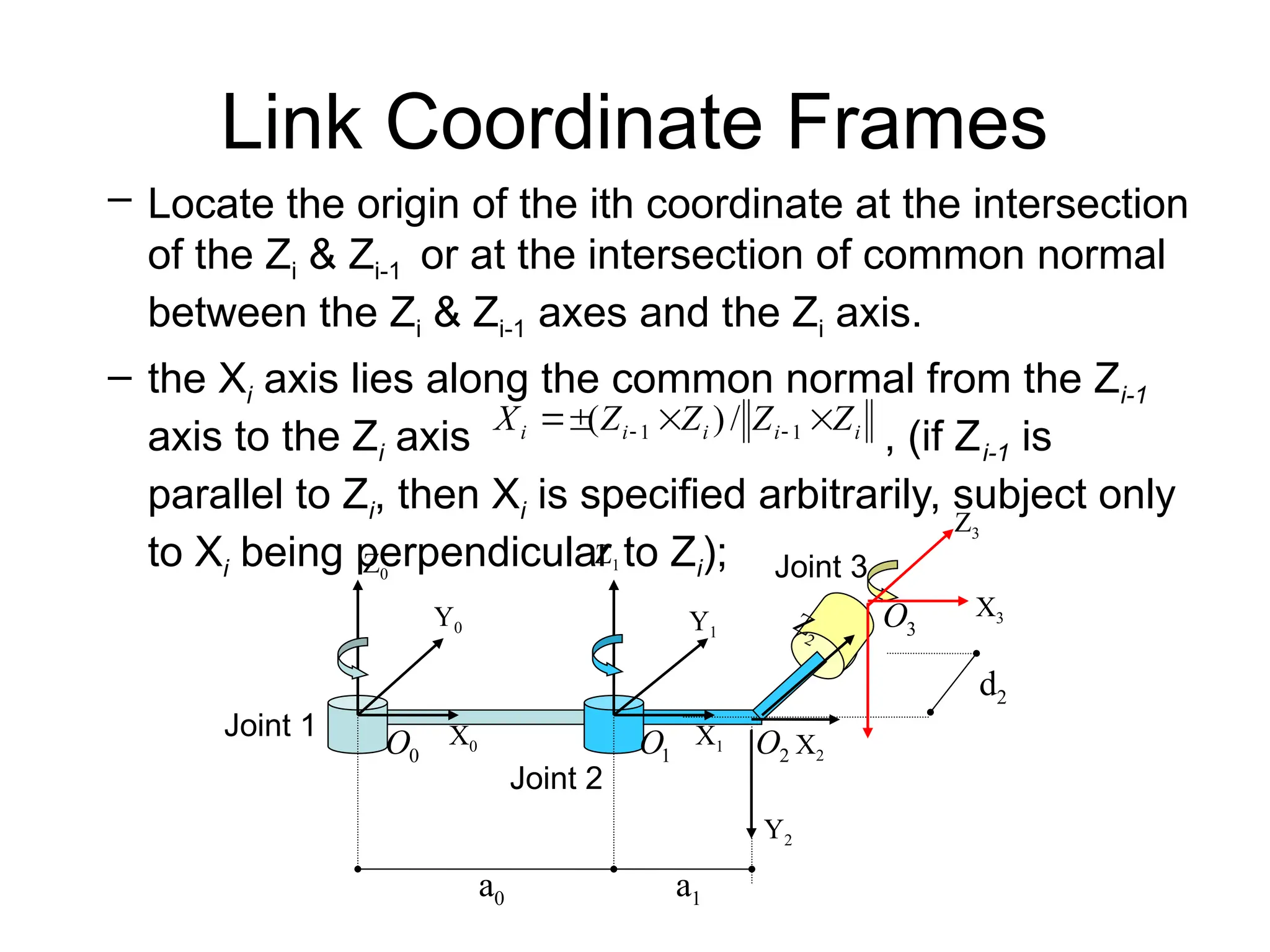
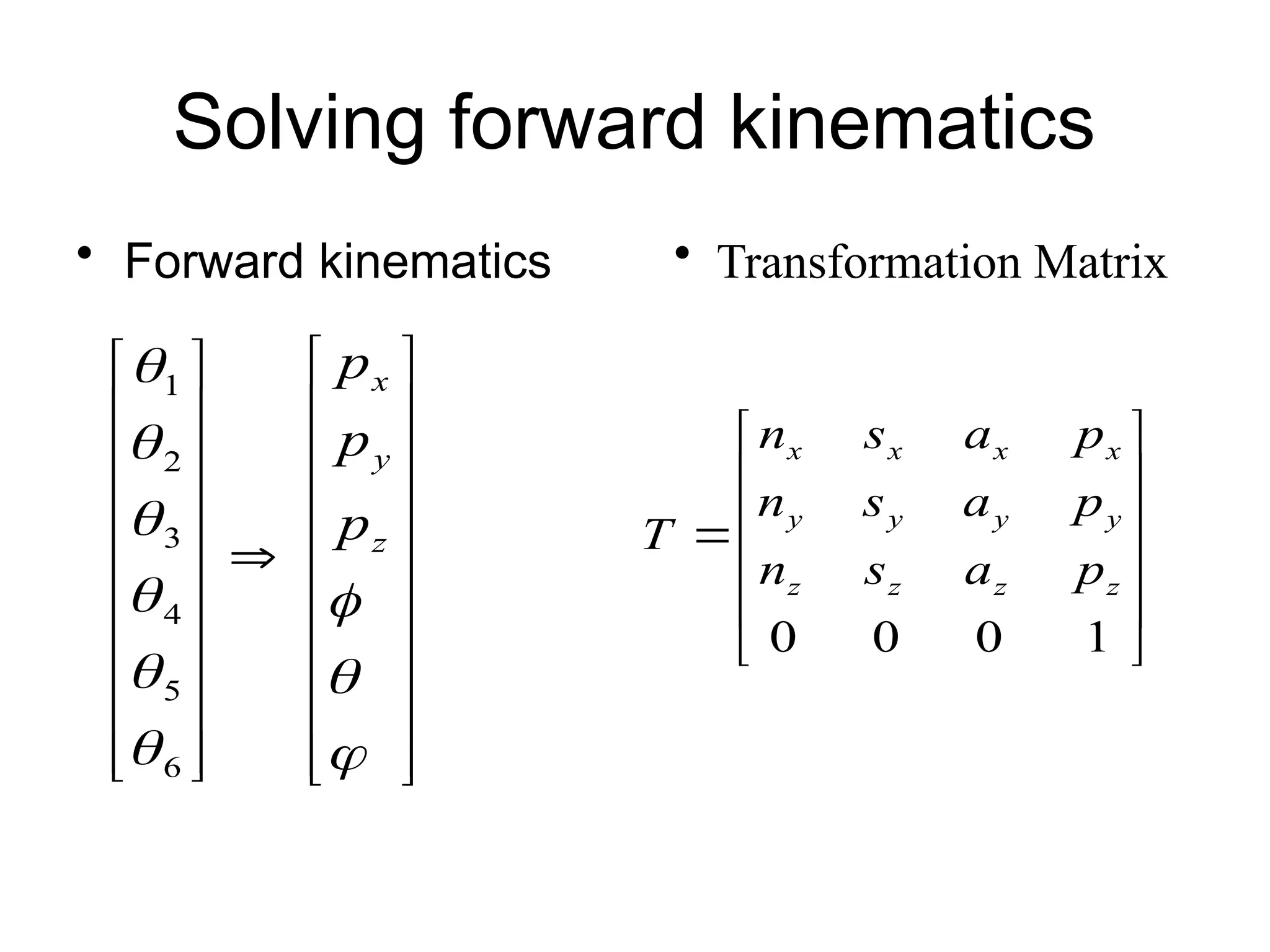
Denavit-Hartenberg Convention
• Number the joints from 1 to n starting with the base and ending with
the end-effector.
• Establish the base coordinate system. Establish a right-handed
orthonormal coordinate system at the supporting base
with axis lying along the axis of motion of joint 1.
• Establish joint axis. Align the Zi with the axis of motion (rotary or
sliding) of joint i+1.
• Establish the origin of the ith coordinate system. Locate the origin
of the ith coordinate at the intersection of the Zi & Zi-1 or at the
intersection of common normal between the Zi & Zi-1 axes and the Zi
axis.
• Establish Xi axis. Establish or along the
common normal between the Zi-1 & Zi axes when they are parallel.
• Establish Yi axis. Assign to complete the
right-handed coordinate system.
• Find the link and joint parameters
)
,
,
( 0
0
0 Z
Y
X
i
i
i
i
i Z
Z
Z
Z
X 


 
 1
1 /
)
(
i
i
i
i
i X
Z
X
Z
Y 


 /
)
(
0
Z
Example I
• 3 Revolute Joints
a0 a1
Z0
X0
Y0
Z3
X2
Y1
X1
Y2
d2
Z1
X3
3
O
2
O
1
O
0
O
Z
2
Joint 1
Joint 2
Joint 3
Link 1 Link 2
Link Coordinate Frames
• Assign Link Coordinate Frames:
– To describe the geometry of robot motion, we assign a Cartesian
coordinate frame (Oi, Xi,Yi,Zi) to each link, as follows:
• establish a right-handed orthonormal coordinate frame O0 at
the supporting base with Z0 lying along joint 1 motion axis.
• the Zi axis is directed along the axis of motion of joint (i + 1),
that is, link (i + 1) rotates about or translates along Zi;
Link 1 Link 2
a0 a1
Z0
X0
Y0
Z3
X2
Y1
X1
Y2
d2
Z1
X3
3
O
2
O
1
O
0
O
Z
2
Joint 1
Joint 2
Joint 3
Link Coordinate Frames
– Locate the origin of the ith coordinate at the intersection
of the Zi & Zi-1 or at the intersection of common normal
between the Zi & Zi-1 axes and the Zi axis.
– the Xi axis lies along the common normal from the Zi-1
axis to the Zi axis , (if Zi-1 is
parallel to Zi, then Xi is specified arbitrarily, subject only
to Xi being perpendicular to Zi);
i
i
i
i
i Z
Z
Z
Z
X 


 
 1
1 /
)
(
a0 a1
Z0
X0
Y0
Z3
X2
Y1
X1
Y2
d2
Z1
X3
3
O
2
O
1
O
0
O
Z
2
Joint 1
Joint 2
Joint 3
Link Coordinate Frames
– Assign to complete the right-
handed coordinate system.
• The hand coordinate frame is specified by the geometry
of the end-effector. Normally, establish Zn along the
direction of Zn-1 axis and pointing away from the robot;
establish Xn such that it is normal to both Zn-1 and Zn axes.
Assign Yn to complete the right-handed coordinate
system.
i
i
i
i
i X
Z
X
Z
Y 


 /
)
(
n
O
a0 a1
Z0
X0
Y0
Z3
X2
Y1
X1
Y2
d2
Z1
X3
3
O
2
O
1
O
0
O
Z
2
Joint 1
Joint 2
Joint 3
Link and Joint Parameters
• Joint angle : the angle of rotation from the Xi-1 axis to
the Xi axis about the Zi-1 axis. It is the joint variable if joint i
is rotary.
• Joint distance : the distance from the origin of the (i-1)
coordinate system to the intersection of the Zi-1 axis and
the Xi axis along the Zi-1 axis. It is the joint variable if joint i
is prismatic.
• Link length : the distance from the intersection of the Zi-1
axis and the Xi axis to the origin of the ith coordinate
system along the Xi axis.
• Link twist angle : the angle of rotation from the Zi-1 axis
to the Zi axis about the Xi axis.
i

i
d
i
a
i

Example I
Joint i i ai di
i
1 0 a0 0 0
2 -90 a1 0 1
3 0 0 d2
2
D-H Link Parameter Table
: rotation angle from Xi-1 to Xi about Zi-1
i

: distance from origin of (i-1) coordinate to intersection of Zi-1 & Xi along Zi-1
: distance from intersection of Zi-1 & Xi
to origin of i coordinate along Xi
i
d
: rotation angle from Zi-1 to Zi about Xi
i
a
i

a0 a1
Z0
X0
Y0
Z3
X2
Y1
X1
Y2
d2
Z1
X3
3
O
2
O
1
O
0
O
Z
2
Joint 1
Joint 2
Joint 3
Example II: PUMA 260
i
i
i
i
i Z
Z
Z
Z
X 


 
 1
1 /
)
(
i
i
i
i
i X
Z
X
Z
Y 


 /
)
(
1

2

3

4

5

6

0
Z
1
Z
2
Z
3
Z
4
Z
5
Z
1
O
2
O
3
O
5
O
4
O
6
O
1
X
1
Y
2
X
2
Y
3
X
3
Y
4
X
4
Y
5
X
5
Y
6
X
6
Y
6
Z
1. Number the joints
2. Establish base frame
3. Establish joint axis Zi
4. Locate origin, (intersect.
of Zi & Zi-1) OR (intersect
of common normal & Zi )
5. Establish Xi,Yi
PUMA 260
t
Link Parameters
1

2

3

4

5

6

0
Z
1
Z
2
Z
3
Z
4
Z
5
Z
1
O
2
O
3
O
5
O
4
O
6
O
1
X
1
Y
2
X
2
Y
3
X
3
Y
4
X
4
Y
5
X
5
Y
6
X
6
Y
6
Z
: angle from Zi-1 to Zi
about Xi
: distance from intersection
of Zi-1 & Xi to Oi along Xi
Joint distance : distance from Oi-1 to intersection of Zi-1 & Xi along Zi-1
: angle from Xi-1 to Xi
about Zi-1
i

i

i
a
i
d
t
0
0
6
0
0
90
5
8
0
-90
4
0
0
90
3
8
0
2
13
0
-90
1
J i

1

4

2

3

6

5

i
 i
a i
d
-l
Transformation between i-1 and i
• Four successive elementary transformations
are required to relate the i-th coordinate frame
to the (i-1)-th coordinate frame:
– Rotate about the Z i-1 axis an angle of i to align the
X i-1 axis with the X i axis.
– Translate along the Z i-1 axis a distance of di, to bring
Xi-1 and Xi axes into coincidence.
– Translate along the Xi axis a distance of ai to bring
the two origins Oi-1 and Oi as well as the X axis into
coincidence.
– Rotate about the Xi axis an angle of αi ( in the right-
handed sense), to bring the two coordinates into
coincidence.
Transformation between i-1 and i
• D-H transformation matrix for adjacent coordinate
frames, i and i-1.
– The position and orientation of the i-th frame coordinate
can be expressed in the (i-1)th frame by the following
homogeneous transformation matrix:














 


1
0
0
0
0
)
,
(
)
,
(
)
,
(
)
,
( 1
1
1
i
i
i
i
i
i
i
i
i
i
i
i
i
i
i
i
i
i
i
i
i
i
i
i
i
i
i
d
C
S
S
a
C
S
C
C
S
C
a
S
S
S
C
C
x
R
a
x
T
z
R
d
z
T
T
















Source coordinate
Reference
Coordinate
Kinematic Equations
• Forward Kinematics
– Given joint variables
– End-effector position & orientation
• Homogeneous matrix
– specifies the location of the ith coordinate frame w.r.t.
the base coordinate system
– chain product of successive coordinate transformation
matrices of














 
1
0
0
0
1
0
0
0
0
1
2
1
1
0
0
n
n
n
n
n
n
P
a
s
n
P
R
T
T
T
T 
)
,
,
( 2
1 n
q
q
q
q 

)
,
,
,
,
,
( 


z
y
x
Y 
i
i
T 1

n
T0
Orientation
matrix
Position
vector
Kinematics Equations
• Other representations
– reference from, tool frame
– Yaw-Pitch-Roll representation for orientation
tool
n
n
ref
tool
ref H
T
B
T 0
0



 ,
,
, x
y
z R
R
R
T 











 

1
0
0
0
0
1
0
0
0
0
0
0




C
S
S
C













1
0
0
0
0
0
0
0
1
0
0
0




C
S
S
C













1
0
0
0
0
0
0
0
0
0
0
1




C
S
S
C
Solving forward kinematics
• Forward kinematics


















































z
y
x
p
p
p
6
5
4
3
2
1













1
0
0
0
z
z
z
z
y
y
y
y
x
x
x
x
p
a
s
n
p
a
s
n
p
a
s
n
T
• Transformation Matrix
Solving forward kinematics
• Yaw-Pitch-Roll representation for orientation


















1
0
0
0
0
z
y
x
n
p
C
C
S
C
S
p
S
C
C
S
S
C
C
S
S
S
C
S
p
S
S
C
S
C
C
S
S
S
C
C
C
T










































1
0
0
0
0
z
z
z
z
y
y
y
y
x
x
x
x
n
p
a
s
n
p
a
s
n
p
a
s
n
T
)
(
sin 1
z
n

 

)
cos
(
cos 1

 z
a


)
cos
(
cos 1

 x
n


Problem? Solution is inconsistent and ill-
conditioned!!
atan2(y,x)
x
y




























y
and
x
for
y
and
x
for
y
and
x
for
y
and
x
for
x
y
a








0
90
90
180
180
90
90
0
)
,
(
2
tan






Denavit-Hartenberg Convention_Dr. Mustafa K. Uyguroğlu.pptx

  • 1.
  • 2.
    Denavit-Hartenberg Convention • Numberthe joints from 1 to n starting with the base and ending with the end-effector. • Establish the base coordinate system. Establish a right-handed orthonormal coordinate system at the supporting base with axis lying along the axis of motion of joint 1. • Establish joint axis. Align the Zi with the axis of motion (rotary or sliding) of joint i+1. • Establish the origin of the ith coordinate system. Locate the origin of the ith coordinate at the intersection of the Zi & Zi-1 or at the intersection of common normal between the Zi & Zi-1 axes and the Zi axis. • Establish Xi axis. Establish or along the common normal between the Zi-1 & Zi axes when they are parallel. • Establish Yi axis. Assign to complete the right-handed coordinate system. • Find the link and joint parameters ) , , ( 0 0 0 Z Y X i i i i i Z Z Z Z X       1 1 / ) ( i i i i i X Z X Z Y     / ) ( 0 Z
  • 3.
    Example I • 3Revolute Joints a0 a1 Z0 X0 Y0 Z3 X2 Y1 X1 Y2 d2 Z1 X3 3 O 2 O 1 O 0 O Z 2 Joint 1 Joint 2 Joint 3 Link 1 Link 2
  • 4.
    Link Coordinate Frames •Assign Link Coordinate Frames: – To describe the geometry of robot motion, we assign a Cartesian coordinate frame (Oi, Xi,Yi,Zi) to each link, as follows: • establish a right-handed orthonormal coordinate frame O0 at the supporting base with Z0 lying along joint 1 motion axis. • the Zi axis is directed along the axis of motion of joint (i + 1), that is, link (i + 1) rotates about or translates along Zi; Link 1 Link 2 a0 a1 Z0 X0 Y0 Z3 X2 Y1 X1 Y2 d2 Z1 X3 3 O 2 O 1 O 0 O Z 2 Joint 1 Joint 2 Joint 3
  • 5.
    Link Coordinate Frames –Locate the origin of the ith coordinate at the intersection of the Zi & Zi-1 or at the intersection of common normal between the Zi & Zi-1 axes and the Zi axis. – the Xi axis lies along the common normal from the Zi-1 axis to the Zi axis , (if Zi-1 is parallel to Zi, then Xi is specified arbitrarily, subject only to Xi being perpendicular to Zi); i i i i i Z Z Z Z X       1 1 / ) ( a0 a1 Z0 X0 Y0 Z3 X2 Y1 X1 Y2 d2 Z1 X3 3 O 2 O 1 O 0 O Z 2 Joint 1 Joint 2 Joint 3
  • 6.
    Link Coordinate Frames –Assign to complete the right- handed coordinate system. • The hand coordinate frame is specified by the geometry of the end-effector. Normally, establish Zn along the direction of Zn-1 axis and pointing away from the robot; establish Xn such that it is normal to both Zn-1 and Zn axes. Assign Yn to complete the right-handed coordinate system. i i i i i X Z X Z Y     / ) ( n O a0 a1 Z0 X0 Y0 Z3 X2 Y1 X1 Y2 d2 Z1 X3 3 O 2 O 1 O 0 O Z 2 Joint 1 Joint 2 Joint 3
  • 7.
    Link and JointParameters • Joint angle : the angle of rotation from the Xi-1 axis to the Xi axis about the Zi-1 axis. It is the joint variable if joint i is rotary. • Joint distance : the distance from the origin of the (i-1) coordinate system to the intersection of the Zi-1 axis and the Xi axis along the Zi-1 axis. It is the joint variable if joint i is prismatic. • Link length : the distance from the intersection of the Zi-1 axis and the Xi axis to the origin of the ith coordinate system along the Xi axis. • Link twist angle : the angle of rotation from the Zi-1 axis to the Zi axis about the Xi axis. i  i d i a i 
  • 8.
    Example I Joint ii ai di i 1 0 a0 0 0 2 -90 a1 0 1 3 0 0 d2 2 D-H Link Parameter Table : rotation angle from Xi-1 to Xi about Zi-1 i  : distance from origin of (i-1) coordinate to intersection of Zi-1 & Xi along Zi-1 : distance from intersection of Zi-1 & Xi to origin of i coordinate along Xi i d : rotation angle from Zi-1 to Zi about Xi i a i  a0 a1 Z0 X0 Y0 Z3 X2 Y1 X1 Y2 d2 Z1 X3 3 O 2 O 1 O 0 O Z 2 Joint 1 Joint 2 Joint 3
  • 9.
    Example II: PUMA260 i i i i i Z Z Z Z X       1 1 / ) ( i i i i i X Z X Z Y     / ) ( 1  2  3  4  5  6  0 Z 1 Z 2 Z 3 Z 4 Z 5 Z 1 O 2 O 3 O 5 O 4 O 6 O 1 X 1 Y 2 X 2 Y 3 X 3 Y 4 X 4 Y 5 X 5 Y 6 X 6 Y 6 Z 1. Number the joints 2. Establish base frame 3. Establish joint axis Zi 4. Locate origin, (intersect. of Zi & Zi-1) OR (intersect of common normal & Zi ) 5. Establish Xi,Yi PUMA 260 t
  • 10.
    Link Parameters 1  2  3  4  5  6  0 Z 1 Z 2 Z 3 Z 4 Z 5 Z 1 O 2 O 3 O 5 O 4 O 6 O 1 X 1 Y 2 X 2 Y 3 X 3 Y 4 X 4 Y 5 X 5 Y 6 X 6 Y 6 Z : anglefrom Zi-1 to Zi about Xi : distance from intersection of Zi-1 & Xi to Oi along Xi Joint distance : distance from Oi-1 to intersection of Zi-1 & Xi along Zi-1 : angle from Xi-1 to Xi about Zi-1 i  i  i a i d t 0 0 6 0 0 90 5 8 0 -90 4 0 0 90 3 8 0 2 13 0 -90 1 J i  1  4  2  3  6  5  i  i a i d -l
  • 11.
    Transformation between i-1and i • Four successive elementary transformations are required to relate the i-th coordinate frame to the (i-1)-th coordinate frame: – Rotate about the Z i-1 axis an angle of i to align the X i-1 axis with the X i axis. – Translate along the Z i-1 axis a distance of di, to bring Xi-1 and Xi axes into coincidence. – Translate along the Xi axis a distance of ai to bring the two origins Oi-1 and Oi as well as the X axis into coincidence. – Rotate about the Xi axis an angle of αi ( in the right- handed sense), to bring the two coordinates into coincidence.
  • 12.
    Transformation between i-1and i • D-H transformation matrix for adjacent coordinate frames, i and i-1. – The position and orientation of the i-th frame coordinate can be expressed in the (i-1)th frame by the following homogeneous transformation matrix:                   1 0 0 0 0 ) , ( ) , ( ) , ( ) , ( 1 1 1 i i i i i i i i i i i i i i i i i i i i i i i i i i i d C S S a C S C C S C a S S S C C x R a x T z R d z T T                 Source coordinate Reference Coordinate
  • 13.
    Kinematic Equations • ForwardKinematics – Given joint variables – End-effector position & orientation • Homogeneous matrix – specifies the location of the ith coordinate frame w.r.t. the base coordinate system – chain product of successive coordinate transformation matrices of                 1 0 0 0 1 0 0 0 0 1 2 1 1 0 0 n n n n n n P a s n P R T T T T  ) , , ( 2 1 n q q q q   ) , , , , , (    z y x Y  i i T 1  n T0 Orientation matrix Position vector
  • 14.
    Kinematics Equations • Otherrepresentations – reference from, tool frame – Yaw-Pitch-Roll representation for orientation tool n n ref tool ref H T B T 0 0     , , , x y z R R R T                1 0 0 0 0 1 0 0 0 0 0 0     C S S C              1 0 0 0 0 0 0 0 1 0 0 0     C S S C              1 0 0 0 0 0 0 0 0 0 0 1     C S S C
  • 15.
    Solving forward kinematics •Forward kinematics                                                   z y x p p p 6 5 4 3 2 1              1 0 0 0 z z z z y y y y x x x x p a s n p a s n p a s n T • Transformation Matrix
  • 16.
    Solving forward kinematics •Yaw-Pitch-Roll representation for orientation                   1 0 0 0 0 z y x n p C C S C S p S C C S S C C S S S C S p S S C S C C S S S C C C T                                           1 0 0 0 0 z z z z y y y y x x x x n p a s n p a s n p a s n T ) ( sin 1 z n     ) cos ( cos 1   z a   ) cos ( cos 1   x n   Problem? Solution is inconsistent and ill- conditioned!!
  • 17.