SlideShare a Scribd company logo
1 of 16
Download to read offline
P L Z - 5 W H 2 S E R I E S
Compact High Voltage DC Electronic Load
D C E L E C T R O N I C L O A D
Operating voltage: 10 V to 1000 V (Min. 1.5 V)
Power capacity: 1 kW/2 kW/4 kW/12 kW/20 kW, 5 models
100 kW/ 2000 A with parallel operation (Max. 5 units) Connectable with 5WH series
LAN (LXI)/USB/RS232C standard digital interface *GPIB optional
Synchronized operation
Sequence function
Arbitrary IV characteristic (ARB) mode
Data-logging: voltage/current/power measurements
(Measurement display, programmable internal memory)
PLZ-5WH2 Series
NEW
Electronic Load
100kW
Up to
Max Power
*5 Unit Parallel
2
High Power
Density
*Not including
protrusions
550
(21.65")
430
(16.93")
Unit: mm
13U
573.5 mm
(22.58")
Ideal for high capacity power supply and
rechargeable battery evaluation!
Testing with hyper-realistic load
simulation made possible!
The PLZ-5WH2 high power DC electronic
load series is where durable, reliable
ingenuity meets multifunctional and high
power design. Providing 5 variety of power
range line-ups, from 1 kW bench top style
model to high power model that can sink up
to 20 kW of power in a single unit. Possible
to easily selects applicable power range
depends on the load. Load simulation can
be achieved faster than ever before thanks
to the reliable, high speed design of the
PLZ-5WH current control circuits. Accurate
current measures can be made with
extremely high setting resolution. A color
LCD display allows for highly visible, user-
friendly front panel operation. RS232C,
USB, and LAN digital interfaces are
included as standard for simple integration
into any system.
●	Operating voltage: 10 V to 1000 V (Min. 1.5 V)
●	20 kW capacity in a single, compact unit (PLZ20005WH2)
●	Parallel operation: 5 units (Max. 100 kW/ 2000 A), Connectable with different models.*
		
*Connectable with 5WH series. However, a firmware update is required.
●	 Synchronization: Load on/off control and sequence execution can be synchronized among
multiple units.
●	Sequence Function: Program can be saved / loaded on USB memory
●	 Arbitrary IV characteristic (ARB) mode
●	 User-friendly color LCD display
●	 Data logging function: voltage/current/power/elapsed time/integrated current/		
integrated power measurements. (Measurement display, programmable internal memory, 		
stored as CSV format onto a USB.)
●	Superposition of sinusoidal current (Sine Function, 1 Hz to 10 kHz)
●	Cutoff function: The load can be turned off when the elapsed time, the voltage drop, 		
the integrated current, or the integrated power reaches the specified value.
●	 LAN (LXI)/USB/RS232C standard digital interface *GPIB optional
12 kW
PLZ12005WH2
20 kW
PLZ20005WH2
1 kW
PLZ1005WH2
2 kW
PLZ2005WH2
4 kW
PLZ4005WH2
NEW
Maximum Operating Voltage
1000V
Compact, High Power
Model Max operating current Operating voltage Power
PLZ1005WH2 20 A
10 V to 1000 V
1 kW
PLZ2005WH2 40 A 2 kW
PLZ4005WH2 80 A 4 kW
PLZ12005WH2 240 A 12 kW
PLZ20005WH2 400 A 20 kW
3U
128 mm
(5.04")
9U
396.2 mm
(15.60")
100kW
Up to
Max Power
*5 Unit Parallel
Compact High Voltage DC Electronic Load
PLZ-5WH2 Series
3
100
10
approx.
1.5
1000
0
1 400
100
Input
voltage
[V]
Input current [A]
1000
Actual operating area
Operating area where
specifications are
guaranteed
20000 W
Logarithmic axis
1
50 V 400 A
1000 V 20 A
● Maximum current and power during parallel operation using the same model
Model
Parallel operation
number
Maximum current Maximum power
PLZ20005WH2
2 800 A 40 kW
3 1200 A 60 kW
4 1600 A 80 kW
5 2000 A 100 kW
Communication Interface
LAN, USB and RS232C standard digital interface. *GPIB Option
LXI compliant!!
Control and monitor the power
from buit-in browser!
Use a browser from a PC, smartphone, or tablet
to access the web server built into the PLZ-5WH2
series for convenient control and monitoring.
[Recommended browser]
●Microsoft Edge 10
●Internet Explorer version 9.0 or later
●Firefox 8.0 or later
●Safari/Mobile Safari 5.1 or later
●Chrome 15.0 or later
●Opera 11.0 or later
*Connecting with a smartphone, tablet, etc. requires a
Wi-Fi environment. (wireless LAN router etc.).
The PLZ-5WH2 series boasts a 20 μs rise time*, easily satisfying
the critical needs of power supply evaluation tests demanding a fast
transient response. *When using the PLZ20005WH2
PLZ20005WH2 Slew Rate: 20 A/μs
Current
(100
A/DIV)
Time (20 μs/DIV)
400 A
300 A
200 A
100 A
Current setting
Rated current
Operating voltage ranges from 10 V to 1000 V.
Minimum operating voltage required to sink current is 1.5 V.
[Operating area of PLZ20005WH2]
Operating
voltage ranges
10V to 1000V
Minimum
operating voltage
1.5V
Up to 100 kW with parallel operation (Max. 5 units)
Parallel Operation
Parallel operation (max. 5 units) is available on all models by simply
connecting an optional parallel operation cable. This feature is available
even among different models for a wide range of high power.
(up to 100 kW / 2000 A)
PLZ20005WH2 (5 units)
PLZ1005WH2 PLZ2005WH2 PLZ4005WH2 PLZ12005WH2 PLZ20005WH2
Different model
can parallel!
*A parallel cable needs to have each unit connection. 12 kW and 20 kW
models are included in accessory. 1 kW, 2 kW and 4 kW models are option.
In ARB mode, arbitrary I-V characteristics can be set by registering
multiple I-V characteristic points (pairs of voltage and current values).
Three up to 100 points can be registered, and the space between two
points is linearly interpolated. The minimum voltage (0.00 V) and current
(0.00 A) and the maximum voltage (1010.00 V) are fixed.
Arbitrary I-V Characteristics 		
(ARB) Mode
Example of setting value (* Value is fixed)
Voltage[V] Current[A]
0.00*
12.00
20.50
23.00
24.50
1010.00*
0.00*
0.10
0.20
0.40
0.80
0.80
10.00 20.00 30.00 1010.00
0.20
0.40
0.60
0.80
0
0
[A]
[V]
I-V characteristics example
Maximum Slew Rate of 20 A/μs
Wide Ranging Operation Voltage up to 1000 V
Parallel operation connection cable
Master unit
Slave unit Slave unit
Slave unit
Slave unit
PARALLEL
OUT IN
PARALLEL
OUT IN
PARALLEL
OUT IN
PARALLEL
OUT IN
PARALLEL
OUT IN
●Connection conceptual diagram
39 kW
100 kW
PLZ-5WH2 series
Smart
High Power
&
[Specifications: See P.10]
[Specifications: See P.12]
20 kW
12 kW
4 kW
2 kW
1 kW
×5
20 kW
[Specifications: See P.9]
Functions
●	Parallel connection with PLZ-5WH series*
	 Must be PLZ-5WH as a Master and update the firmware to newest version.
	 *When parallel operation between 5WH and 5WH2, only same capacity
model is available.
Operation Modes
Constant current
(CC) mode
When a current value is specified, the current is kept at that
value even when the voltage changes.
Constant resistance
(CR) mode
Whenaconductancevalueisspecified,theproductsinkscurrentproportio-
naltothevoltagevariationbyusingthevalueasaproportionalityconstant.
Constant voltage
(CV) mode
When a voltage value is specified, the product runs the current
so that the voltage is kept at that value.
Constant power
(CP) mode
When a power value is specified, the product runs the current
so that the power is kept at that value.
Arbitrary I-V charac-
teristics (ARB) mode
The desired load characteristics can be set by specifying multiple
arbitrary voltage values and current values as I-V characteristics.
The following five operation modes are available on the PLZ-5WH2.
In addition, available to set in operation modes other than CV mode, the
“UVPL*” setting keep the voltage less than UVP setting by controlling
the current and the “UVPT” setting loads off by applying a current to
reach the target setting voltage.
[Specifications: See P.8-9]
*"UVPL" is the "+CV mode" in PLZ-5W series
4
Functions
Load On/Off
The following load on/off settings are available in addition to standard
operations that can be carefully adjusted to fit the needs of any test
environment.
● Start with "load on" when power is turned on
● Display elapsed "load on" time
● Auto "load off" when time limit is reached
● Control "load on/off" with external controls such as relays
● "Load off" by specifying conditions (Cutoff function)
Soft Start
Soft start is a function that controls the rise time of the load current.
Soft start functions only when all the following conditions are met.
●	The rise time of the soft start has been set.
●	Load on state in constant current (CC) mode.
●	There is an input that is equal to or exceeds the minimum operating
condition, from the state where there is no input to the load input
terminals.
If the load current rises sharply, the DUT output may become unstable
or the DUT’s overcurrent protection circuit may be activated. In such
situations, it is possible to make the load current to rise slowly only
when the product is started.
time
0
PLZ-5WH2 series
DUT’s voltage waveform
time
0
■ When soft start has been disabled ■ When soft start has been set properly
Load
On
Load
On
PLZ-5WH2 series
Rise start (Current starts flowing.)
PLZ-5WH2 series
Rise start (Current starts flowing.)
Input
voltage
or
current
Input
voltage
or
current
Operation mode CC
Time setting range
500 μs, 1 ms, 2 ms, 5 ms, 10 ms, 20 ms, 50 ms,
100 ms, or off
Changing the Response Speed
Set the response speed for CV, CR, or ARB mode according to the
DUT’s conditions and application.
Item Description
Response
Voltage Set the response speed for CV mode. Normal, Fast
Conductance Set the response speed for CR mode. Normal, Fast
ARB
Set the response speed for ARB mode. The value is the
filter response time. Select OFF for no filter.
OFF, 500 μs, 1 ms, 2 ms, 5 ms, 10 ms, 20 ms, 50 ms,
100 ms
Saving Measurement Data
Measurement data can be stored in CSV format to a USB memory
device.
Cutoff Function
The cutoff function allows the user to enable load off once the elapsed
time/voltage drop/integrated current/integrated power has been reached
after load on. Multiple factors can be selected, with load off being
implemented after the first requirement is met.
Elapsed time
The load turns off when the elapsed time value reaches the
specified value.
Voltage drop*
The load turns off when the voltmeter value reaches the
specified value.
Integrated current
The load turns off when the ampere-hour meter value reaches
the specified value.
Integrated power
The load turns off when the watt-hour meter value reaches the
specified value.
[Specifications: See P.11]
Integrated Data Function
Time elapsed, integrated current and integrated power can be logged.
Logging (integration) can be coordinated to start/finish when the load
turns on/off or during the start or end of a sequence. Logging can also
be controlled arbitrarily.
item Value Description
Integral Gate
- Set the integrated data recording period.
None Integrated data recording is started/stopped manually.
Load On
Recording is started/stopped automatically in synchronization
with load on/load off. Or, recording is started or stopped
manually.
Program Run
Recording is started/stopped automatically in synchronization
with sequence execution start/stop.
Or, recording is started or stopped manually.
Reset
-
Selects the integrated data reset method. If the product is
restarted, inte-grated data is reset.
Manual Integrated data is reset when the Reset key is pressed.
Auto Integrated data is automatically reset before the start of
recordings. Or, integrated data is reset when the Reset key is
pressed.
Time
Voltage
0
UVP
detection
voltage
Integrated data recording
Example:
Integral Gate is set to
Load On, and UVP is set
[Specifications: See P.11]
Data Logging Function
The data logging function allows
the user to log measurement
values (current, voltage, power) in
the internal memory, and display
logged data on an LCD screen
(Table) as a chart (Chart).
By setting measurement recording
conditions, you can control the
timing that measurements are
recorded.
Condition Value Description
Trigger −
Set the measurement recording timing and the
number of times to record measurements.
Source
−
Event (trigger source) that defines the measurement
recording condition. Recording starts after the
Initiate key is pressed and a trigger is received.
Immediate Pressing Initiate applies a trigger immediately.
BUS
Applies a trigger when a *TRG command is
received from a PC or when the *TRG key on the
front panel is pressed.
DIGITAL2*
Applies a trigger when a signal is received at pin
13 of the EXT CONT connector.
MSync
The trigger application timing is synced between
PLZ-5WH2 that are synchronized
TALink
Applies a trigger when a step is executed if
Generate is set to TALink in the sequence step
settings
Load Off Applies a trigger when the load is turned off.
Count 1 to 65536 The number of times to recorded measurements.
Delay
0 μs to 100 s
(resolution: 10 μs)
The delay time from trigger application until
measurement recording.
Interval Disable/Enable
Sets whether to insert an interval between
recordings when Count is 2 or higher.
Interval Time
10 μs to 3600 s
(resolution: 10 μs)
Recording interval time when Interval is set to
Enable.
Sense Aperture
10 μs to 1 s
(resolution: 10 μs)
Time period of each recording. The average over
the time period is recorded.
*Only when Direction of Digital 2 is set to Input
▲ Data logging display example (Figure display)
[Specifications: See P.9]
*Voltage drop cutoff operates in the same manner as UVPT of the UVP function.
UVP turns the load off based on the protection function, but the cutoff function
turns the load off when the specified conditions are met. As such, there is no need
to clear alarms, which is required when a UVPT is activated.
5
Functions
Sine Function
The sine function varies the current sinusoidally. It is suitable for super-
posed ripple testing of large capacity power supplies and batteries.
When a sine operation is in progress, a trigger signal is output from the
TRIG OUT connector on the front panel. You can set this regardless of
whether the load is on or off. This function operates in CC mode.
You cannot set the slew rate. Set the sine amplitude with a value.
When a sine operation is in progress, a trigger signal is output for 10 μs
from the TRIG OUT connector on the front panel when the current passes
through the Set value on the rising edge (sine wave phase at 0 degrees).
0[A]
Amplitude [A]
Current [A]
Current
Time
Current: Load value (center
value of the amplitude)
Amplitude: Sine amplitud
0
Current
Time
TRIG OUT
10 µs
Current
Operation mode CC
Frequency setting range 1 Hz to 1 kHz, 2 kHz, 5 kHz, 10 kHz
Frequency
setting
resolution*
1 Hz to 10 Hz 1 Hz
20 Hz to 100 Hz 10 Hz
200 Hz to 1000 Hz 100 Hz
1000 Hz to 2 kHz, 5 kHz, 10 kHz
* (Reference) The resolution actually set in the device is period resolution ⊿ T= 20 μs,
as shown in the equation below. For example, if you specify 900 Hz, the period set in the
device will be n × ⊿ T = 56 × 20 μs = 1120 μs (where n is a number set in the device).
Converted to frequency, this becomes 1/1120 μs ≈ 893 Hz.
Sequence Function
A sequence consists of programs and steps. A program is a collection
of steps. Steps are executed in order one at a time, starting from
step 1. The completion of the last step signifies that the program has
been executed once. When the specified number of program loops is
completed, the sequence ends. You can set the load state (load on or
off, load value, slew rate) at the end of the sequence of a program.
Setting range Setting Description
By step
Load value
Current, conductance, voltage, power. The values that
can be set depend on the current operation mode.
Slew rate Sets the speed of change when the current is changed.
Step execution
time
0.000050 s to 3600000 s (50 μs to 1000 h),
resolution: 1 μs
Load on/off
control
To turn the load on, set the load setting transition
method to step or ramp.
Other Trigger signal setting, trigger signal output
For each
program
Number of loops
of program
1 to 100000 repetitions, or infinite repetitions.
Protection
function
Specifies the value at which a protection function
(OCP, OPP, UVP) is activated.
● TALink
The TALink (Transient Acquire Link) trigger makes it possible to log data in
PLZ-5WH2 in synchronization with the sequence steps. Logged data can
then be accessed through ommunication with the PLZ-5WH2 and saved to a
USB as a CSV file.
Step 1 Step 2 Step 3 Step 4 Step 5 Step 6 Step 7 Step 8 Step 9
Input
current
Time
Measurement
Loop 1 Loop 2
Set a program for each operation mode. Up to 30 programs can
be set.Up to 10000 steps total can be used in all programs.
Input current
Step 1 Step 2 Step 3 Step 4
Time
Program1
Load value
Step 1 Step 2 Step 3 Step 4
Program1
Pulse function refers to the operation of executing two settings repetitively.
It is suitable for transient response characteristics testing of large
capacity power supplies and batteries. When the pulse operation is in
progress, a trigger signal is output from the TRIG OUT connector on the
front panel. You can set this regardless of whether the load is on or off.
This function operates in CC and CR modes. The pulse amplitude is set
with a value or a percentage of the load value.
When the pulse operation is in progress, a trigger signal is output for
10 μs from the TRIG OUT connector on the front panel when the current
amplitude changes from low (Depth) to high (Set) level.
Pulse Function
Operation mode CC and CR
Frequency setting range 1.0 Hz to 10.0 kHz
Frequency
setting
resolution*
1 Hz to 10 Hz 0.1 Hz
11 Hz to 100 Hz 1 Hz
110 Hz to 1000 Hz 10 Hz
1.1 kHz to 10.0 kHz 0.1 kHz
* (Reference) The resolution actually set in the device is period resolution ⊿ T = 1 μs,
as shown in the equation below. For example, if you specify 9300 Hz, the period set in
the device will be n × ⊿ T = 108 × 1 μs = 108 μs (where n is a number set in the device).
Converted to frequency, this becomes 1/108 μs = 9259 Hz.
HIGH
LOW
0
Current
Time
TRIG OUT
10 µs
0[A][S]( 0 % )
Depth [A][S ][%]
Current [A] or
Conductance [S]
(100 %)
Current
Time
Current or conductance:
Load value in CC mode or CR mode
Depth: Pulse level
[Specifications: See P.9]
Trip Turns the load off. The setting display changes to UVPT.
Limit
Limits the voltage so as not to become equal to or less than the set value.
The setting display changes to UVPL.
●Alarm 2 (low urgency)
Name Mode Activation
Overcurrent protection (OCP) CR, CV, CP
Load off or limit
Overpower protection (OPP) CC, CR, CV, ARB
Undervoltage protection (UVP) CC, CR, CP, ARB
Load off, limit, or
activation off
Watchdog protection (WDP) All Load off
●Alarm 1 (high urgency)
Name Activation
Overvoltage detection (OVP)
Load off
Reverse-connection detection (Reverse)
Overheat detection, overcurrent detection of the front-panel
DC INPUT terminals (OTP/Front)
Alarm input detection (External)
Parallel operation anomaly detection
This function limits the current (UVPL) or turns off the load (UVPT) when the voltage
applied to the product becomes equal to or less than the UVP setting. You can set this
regardless of whether the load is on or off.
Alarm Function
This function detects anomalies and protects the DUT. There are two
types of alarm based on urgency level: alarm 1 (high urgency) and
alarm 2 (low urgency).
[Specifications: See P.10]
6
ABC Preset Memories
Three setting values can be stored in preset memory slots A, B, and
C. All saved settings can be accessed at the press of a button, which
is perfect for when you want to quickly switch between three sets of
values.
The setup memory can store up to 20 sets (0 to 19) of the current
conditions of the items listed below. The current conditions can also be
saved in a USB memory device.
●	Operation mode
●	Load values (current, voltage, conductance, power)
●	Slew rate
●	Pulse amplitude (current/conductance or percentage)
●	Pulse interval (frequency/time of one cycle and duty cycle/operating
	 time on the high side)
●	Sine amplitude (current)
●	Sine frequency
●	Alarm operating conditions
●	Content of ABC preset memories
A file saved on the PLZ-5WH2 can be transferred to the PLZ-5W via a
USB memory device. If the UVP is set to "limit" on the PLZ-5WH2, this
will be changed to +CV mode on the PLZ-5W (PLZ205W, PLZ405W,
PLZ1205W).
Setup Memory
Current and Voltage Monitor
In addition to the conventional current
monitor output, voltage monitor output
(0 V to 10 V/Output of 1/100 of measured
voltage) has been added to the front BNC
connector.
Synchronized Operation
The following synchronization features are available when simply
connecting the PLZ-5WH2 with other equipment using a communication
cable. Any of the models in the PLZ-5WH2 series can be connected
together. Synchronized operation is possible even during parallel
operation.
●	Synchronizing load on/off among multiple pieces of equipment.
●	Synchronizing measurements.
●	Synchronizing the start time and resume time for sequences across
multiple units.
To EXT SYNC IN
of another device
EXT SYNC IN
EXT SYNC OUT
EXT SYNC OUT
LAN cable
[Connection example]
Remote Sensing
With remote sensing, the voltage measurement point can be changed
from the load input terminal to the DUT sensing point. By connecting
the sensing leads to the DUT, the effects of voltage drops caused by
resistance in the load cables can be reduced and the operation in CR /
CV / CP / ARB mode stabilized.
● Remote sensing input rated voltage: 1000 V
USB Keyboard
You can enter numbers/characters if you connect a keyboard to the
USB port on the front panel.
The types of keyboards that you can use are 101-key and 104-key
keyboards.
External Control
The PLZ-5WH2 can be controlled and monitored from an external
device. The external control terminals are isolated from the load input
terminal.
EXT CONT connector
pin number
14
25
1
13
Rear panel
[Specifications: See P.12]
[Specifications: See P.12]
Functions
Pin
no.
In/Out *1 Signal name Description
1 – STATUS COM Status signal common for pins 14 to 16.
2 NC – –
3 NC – –
4 NC – –
5 IN ALARM CLEAR Alarm clearing input
6 IN ALARM INPUT Alarm input
7 NC – –
8 NC – –
9 IN TRIG INPUT
Trigger input. Resumes program execution if Wait(post) was
set to Trig IN in a sequence step and the program was paused.
10 – A COM This is connected to the chassis.
11 OUT DIGITAL 0 DIGITAL0 output. Sequence control possible.
12 OUT DIGITAL 1 DIGITAL1 output. Sequence control possible.
13 IN/OUT DIGITAL 2
DIGITAL2 I/O. Input/output switchable.
Sequence signal output or the trigger input of sequences and
measurement function.
14 OUT ALARM1
ALARM1 output. ON when overvoltage detection, reverse-con-
nection detection, overheat detection, alarm input detection,
or parallel operation anomaly detection is activated, and also
during external alarm input.
15 OUT ALARM2 ALARM2 output. ON during OCP, OPP, UVP, or WDP operation.
16 OUT LOAD ON STATUS Load-on status output. ON during load on.
17 NC – –
18 IN LOAD ON/OFF CONT Load on/off control input. Logic level switchable.
19 – A COM This is connected to the chassis.
20 IN EXT CONT ADD
External voltage control input.
Controls the load setting of CC mode by adding current.
21 IN EXT CONT MODE
External voltage control input.
Controls the load values of CC, CR, and CP modes.
22 IN EXT CONT CV
External voltage control input.
Controls the voltage of CV mode.
23 – A COM This is connected to the chassis.
24 OUT IMON Current monitor output.
25 NC – –
*1 1000 V reinforced insulation between each terminal and the DC INPUT terminal.
7
LV124 Standard L-02 Life test - high-temperature endurance test (Durability - Heat) [Life test]
[Combination of AC power source and electronic load equipment]
*DUT must function completely before/during/after testing (n=6 units)
AC Power Supply DC Electronic Load
AC
230 V
DC
1000 V
EUT EUT
EUT EUT
EUT EUT
Onboard Charger
● EV Charger Aging Tests
● DC-DC Converter Evaluation
DC-DC converter performance tests vital for automotive electric components can easily be carried out by controlling the converter input (DC
power supply) and output (DC electronic load). The DC power supply and electronic load can be started up simultaneously for variation tests
and efficiency tests.
PCR-WE/WE2 Series PLZ-5WH2 Series
DC Electronic Load
PLZ-5WH2 Series
DC Power Supply
PAT Series
0-
V
Input voltage
DC500 V
1U Multi Range Programmable DC Power Supply
PWX Series
DC-DC
Converter
Battery simulated voltage
DC13.5 V
Operating voltage
DC10 V to 1000 V
● Battery Discharge Testing
Battery discharge test can be conducted and results saved without a PC. The acquired data can be saved in CSV format on USB memory.
I/V Curve (sequence)
Cut conditions: Time
Data display: chart
Sample: 1
Volmetric property (Constant current)
Cut conditions: Voltage or capacity (Ah)
Data display: table
Sample: 5
DC Electronic Load
PLZ-5WH2 Series
Battery
Application
8
The used terminology is as follows:
•	 TYP: These are typical values that are representative of situations where the product
operates in an en vironment with an ambient temperature of 23 °C (73.4 °F).
	 These values do not guarantee the performance of this product.
•	 setting: Indicates a setting.
•	 reading: Indicates a readout value.• rating: Indicates a rated value.
•	 Open: Indicates equivalence to the state in which the DC INPUT terminals are opened.
Unless specified otherwise, the specifications are for the
following settings and conditions.
•	 The product is warmed up for at least 30 minutes.
•	 Rear-panel DC INPUT terminals are used.
Specifications
■Rating
Item PLZ1005WH2 PLZ2005WH2 PLZ4005WH2 PLZ12005WH2 PLZ20005WH2
Operating voltage (DC) 10 V to 1000 V
Power 1000 W 2000 W 4000 W 12000 W 20000 W
Current 20 A 40 A 80 A 240 A 400 A
DC INPUT terminal’s isolation
voltage
Positive pin: ±1000 V, Negative pin: ±900 V
Minimum
operating
voltage
At the rated current 10 V
When the current
begins to flow
1.5 V or less
■Constant current (CC) mode
Item PLZ1005WH2 PLZ2005WH2 PLZ4005WH2 PLZ12005WH2 PLZ20005WH2
Operating range 0 A to 20 A 0 A to 40 A 0 A to 80 A 0 A to 240 A 0 A to 400 A
Setting range 0.0000 A to 20.2000 A 0.000 A to 40.400 A 0.000 A to 80.800 A 0.00 A to 242.40 A 0.00 A to 404.00 A
Resolution 0.0005 A 0.001 A 0.002 A 0.005 A 0.01 A
Setting accuracy ±(0.2 % of setting + 0.1 % of rating)
Parallel operation ±(0.4 % of setting + 0.2 % of rating)
■Constant resistance (CR) mode
Item PLZ1005WH2 PLZ2005WH2 PLZ4005WH2 PLZ12005WH2 PLZ20005WH2
Operating range *1
H range 500 mS to 0 S 1 S to 0 S 2 S to 0 S 6 S to 0 S 10 S to 0 S
L range 5 mS to 0 S 10 mS to 0 S 20 mS to 0 S 60 mS to 0 S 100 mS to 0 S
Setting range
H range 505.00 mS to 0.00 S 1.01000 S to 0.00000 S 2.02000 S to 0.00000 S 6.0600 S to 0.00000 S 10.1000 S to 0.0000 S
L range 5.0500 mS to 0.0000 S 10.1000 mS to 0.0000 S 20.2000 mS to 0.000 S 60.600 mS to 0.000 S 101.000 mS to 0.000 S
Resolution
H range 0.01 mS 0.00002 S 0.00005 S 0.0002 S 0.0002 S
L range 0.0001 mS 0.0002 mS 0.0005 mS 0.002 mS 0.002 mS
Setting accuracy *2 H range ±(0.5 % of setting + 0.5 % of rating *3)
L range ±(0.5 % of setting + 0.2 % of rating *3)
Parallel
operation
H range ±(1.0 % of setting + 1.0 % of rating *3)
L range ±(1.0 % of setting + 0.4 % of rating *3)
Response speed NORM/FAST
*1. Conductance [S] = input current [A]/input voltage [V] = 1/resistance [Ω]
*2. Converted value at the input current. At the sensing point during remote sensing.
*3. Rated current
■Constant voltage (CV) mode
Item PLZ1005WH2 PLZ2005WH2 PLZ4005WH2 PLZ12005WH2 PLZ20005WH2
Operating range 10 V to 1000 V
Setting range 0.00 V to 1010.00 V
Resolution 0.02 V
Setting accuracy *1 ±(0.05 % of setting + 0.05 % of rating)
Parallel operation ±(0.1 % of setting + 0.1 % of rating)
Response speed NORM/FAST
*1. With the input voltage within the operating range, and at the sensing point during remote sensing.
■Constant power (CP) mode
Item PLZ1005WH2 PLZ2005WH2 PLZ4005WH2
Operating range 0 W to 1000 W 0 W to 2000 W 0 W to 4000 W
Setting range 0.00 W to 1010.00 W 0.00 W to 2020.00 W 0 W to 4040.00 W
Resolution 0.02 W 0.05 W 0.1 W
Setting accuracy ±(0.5 % of rating *1 + 0.02 A × Vin *2) ±(0.5 % of rating *1 + 0.04 A × Vin *2) ±(0.5 % of rating *1 + 0.08 A × Vin *2)
Parallel operation ±(1 % of power rating + 0.1 % current rating × Vin *2)
Item PLZ12005WH2 PLZ20005WH2
Operating range 0 W to 12000 W 0 W to 20000 W
Setting range 0.0000 kW to 12.1200 kW 0.0000 kW to 20.2000 kW
Resolution 0.0005 kW
Setting accuracy ±(0.5 % of rating *1 + 0.2 A × Vin *2) ±(0.5 % of rating *1 + 0.4 A × Vin *2)
Parallel operation ±(1 % of power rating + 0.1 % current rating × Vin *2)
*1. Rated power
*2. DC INPUT terminal voltage or SENSING terminal voltage.
9
Specifications
■Arbitrary I-V characteristics (ARB) mode
Item PLZ1005WH2 PLZ2005WH2 PLZ4005WH2 PLZ12005WH2 PLZ20005WH2
Operating range
Three to 100 points of current values can be specified for the input voltage.
Linear interpolation is applied between specified points.
Response speed 500 μs, 1 ms, 2 ms, 5 ms, 10 ms, 20 ms, 50 ms, 100 ms, or off
■Measurement function
Voltmeter
Item PLZ1005WH2 PLZ2005WH2 PLZ4005WH2 PLZ12005WH2 PLZ20005WH2
Display 0.00 V to 1000.00 V
Resolution 10 mV
Accuracy ±(0.05 % of reading + 0.05 % of rating)
Parallel operation ±(0.1 % of reading + 0.1 % of rating) (TYP)
Ammeter
Item PLZ1005WH2 PLZ2005WH2 PLZ4005WH2 PLZ12005WH2 PLZ20005WH2
Display 0.000 A to 20.000 A 0.000 A to 40.000 A 0.000 A to 80.000 A 0.00 A to 240.00 A 0.00 A to 400.00 A
Resolution 0.001 A 0.001 A 0.001 A 0.01 A 0.01 A
Accuracy ±(0.2 % of reading + 0.1 % of rating)
Parallel operation ±(0.4 % of reading + 0.2 % of rating) (TYP)
Power display
Item PLZ1005WH2 PLZ2005WH2 PLZ4005WH2 PLZ12005WH2 PLZ20005WH2
Display Displays the product of the voltmeter reading and ammeter reading
Measurement trigger
Item PLZ1005WH2 PLZ2005WH2 PLZ4005WH2 PLZ12005WH2 PLZ20005WH2
Trigger Source Immediate, BUS, DIGITAL2, MSync, TALink, LoadOff
Trigger Count 1 to 65536
Trigger Delay 0.00000 s to 100.00000 s
Interval Disable/Enable
Interval Time 0.00001 s to 3600 s
Sense Aperture 0.00001 s to 1.00000 s
■Pulse function
Item PLZ1005WH2 PLZ2005WH2 PLZ4005WH2 PLZ12005WH2 PLZ20005WH2
Operation mode CC and CR
Frequency setting range 1.0 Hz to 10.0 kHz
Frequency
setting
resolution *1
1 Hz to 10 Hz 0.1 Hz
11 Hz to 100 Hz 1 Hz
110 Hz to 1000 Hz 10 Hz
1.1 kHz to 10.0 kHz 0.1 kHz
Frequency
setting
accuracy
1 Hz to 5.0 kHz ±(0.5 % of setting)
5.1 Hz to 10.0 kHz ±(1.0 % of setting)
Duty cycle
setting range,
step
1 Hz to 10 Hz
5.0 % to 95.0 %, 0.1 % steps
11 Hz to 100 Hz
110 Hz to 1000 Hz
1.1 kHz to 10.0 kHz 5 % to 95 % *2, 1 % steps
*1. (Reference) The resolution actually set in the device is period resolution ⊿T = 1 μs, as shown in the equation below. For example, if you specify 9300 Hz, the period set
in the device will be n × ⊿T = 108 × 1 μs = 108 μs (where n is a number set in the device). Converted to frequency, this becomes 1/108 μs = 9259 Hz.
*2. The minimum time span is 20 μs. The minimum duty cycle is limited by the minimum time span.
Switch value (Depth)
Item *1 PLZ1005WH2 PLZ2005WH2 PLZ4005WH2 PLZ12005WH2 PLZ20005WH2
CC mode 0.0000 A to 20.2000 A 0.000 A to 40.400 A 0.000 A to 80.800 A 0.000 A to 242.40 A 0.00 A to 404.00 A
CR mode
H range 505.00 mS to 0.00 S 1010.00 mS to 0.00 S 2020.00 mS to 0.00 S 6.06000 S to 0.00000 S 10.1000 S to 0.0000 S
L range 5.0500 mS to 0.0000 S 10.1000 mS to 0.0000 S 20.2000 mS to 0.0000 S 60.600 mS to 0.000 S 101.000 mS to 0.000 S
*1. The switch value is limited to the set current or set conductance or less.
10
■Slew rate
Item PLZ1005WH2 PLZ2005WH2 PLZ4005WH2 PLZ12005WH2 PLZ20005WH2
Operation mode CC
Operating range 0.001 A/µs to 1 A/µs 0.002 A/µs to 2 A/µs 0.004 A/µs to 4 A/µs 0.01 A/µs to 12 A/µs 0.02 A/µs to 20 A/µs
Resolution 0.00002 A/µs 0.00005 A/µs 0.0001 A/µs 0.0002 A/µs 0.0005 A/µs
Setting accuracy *1 ±(10 % of setting +20 μs)
*1. Time to change from 10 % to 90 % when the current is changed from 0 % to 100 % of the rated current
■Sine function
Item PLZ1005WH2 PLZ2005WH2 PLZ4005WH2 PLZ12005WH2 PLZ20005WH2
Operation mode CC
Frequency setting range 1 Hz to 1000 Hz, 2000 Hz, 5000 Hz, 10000 Hz
Frequency
setting
resolution *1
1 Hz to 10 Hz 1 Hz
20 Hz to 100 Hz 10 Hz
200 Hz to 1000 Hz 100 Hz
1000 Hz to 2 kHz, 5 kHz, 10 kHz
Frequency
setting
accuracy
300 Hz to 900 Hz ±(1.0 % of setting)
Other than the
frequencies above
±(0.5 % of setting)
*1. (Reference) The resolution actually set in the device is period resolution ⊿T= 20 μs, as shown in the equation below. For example, if you specify 900 Hz, the period set in
the device will be n × ⊿T = 56 × 20 μs = 1120 μs (where n is a number set in the device). Converted to frequency, this becomes 1/1120 μs ≈ 893 Hz.
■Soft start
Item PLZ1005WH2 PLZ2005WH2 PLZ4005WH2 PLZ12005WH2 PLZ20005WH2
Operation mode CC
Time setting range 500 μs, 1 ms, 2 ms, 5 ms, 10 ms, 20 ms, 50 ms, 100 ms, or off
■Alarm function
Alarm 1
Item PLZ1005WH2 PLZ2005WH2 PLZ4005WH2 PLZ12005WH2 PLZ20005WH2
Overvoltage detection Turns off the load when a voltage that is 110 % of the rating or higher is applied.
Reverse-connection detection Turns off the load when approximately -1 % of the rated current flows through the DC INPUT terminals.
Overheat detection, overcurrent
detection of the front-panel DC
INPUT terminals
Turns off the load when the heatsink temperature reaches 100 °C.
Or, turns off the load when a current of 30 A or higher is flowing through the front-panel DC INPUT terminals.
Alarm input detection Turns off the load when a voltage between 0 V and 1.5 V is applied to ALARM INPUT (pin 6) of the EXT CONT connector.
Parallel operation
anomaly detection
Turns off the load when any of the following errors occurs.
• An error occurred in the communication between the master unit and slave unit during parallel operation.
• A slave unit’s power supply was interrupted.
• A n overheating was detected on the master or slave unit.
• An overcurrent flowed through the front-panel DC INPUT terminals.
• PLZ-5WH series or PLZ-5W series was connected as a slave.
Alarm 2
Item PLZ1005WH2 PLZ2005WH2 PLZ4005WH2 PLZ12005WH2 PLZ20005WH2
Overcurrent
protection
(OCP)
Setting range 0.000 A to 22.000 A 0.00 A to 44.00A 0.00 A to 88.00A 0.00 A to 264.00A 0.00 A to 440.00A
Resolution 0.001 A 0.01 A 0.01 A 0.01 A 0.1 A
Protection operation Select load off or limit.
Overpower
protection
(OPP)
Setting range 0.0 W to 1100.0 W 0.0 W to 2200.00 W 0 W to 4400 W 0.000 W to 13.200 kW 0.000 W to 22.000 kW
Resolution 0.1 W 0.1 W 1 W 0.001 kW 0.001 kW
Protection operation Select load off or limit.
Undervoltage
protection
(UVP)
Setting range 0.00 V to 1000.00 V, or off.
Resolution 0.02 V
Protection operation Select load off or limit.
Watchdog
protection
(WDP)
Setting range 1 s to 3600 s or off
Protection operation Load off
■Sequence function
Item PLZ1005WH2 PLZ2005WH2 PLZ4005WH2 PLZ12005WH2 PLZ20005WH2
Operation mode CC, CR, CV, CP
Maximum number of programs 30
Maximum number of steps 10000
Step execution time 0.000050 s to 3600000 s (50 µs to 1000 h)
Time resolution 1 µs
Specifications
11
■Integration display
Item PLZ1005WH2 PLZ2005WH2 PLZ4005WH2 PLZ12005WH2 PLZ20005WH2
Elapsed time display Displays the time from load on to load off.
Range 0 s to 3600000 s (1000 h 0 min 0 s)
Ampere-hour meter display Displays integrated current
Range 0 Ah to 70000 Ah 0 Ah to 140000 Ah 0 Ah to 280000 Ah 0 Ah to 800000 Ah 0 Ah to 1400000 Ah
Watt-hour meter display Displays integrated power
Range 0 Wh to 40000000 Wh 0 Wh to 80000000 Wh 0 Wh to 160000000 Wh 0 Wh to 500000000 Wh 0 Wh to 800000000 Wh
■Cutoff function
Item PLZ1005WH2 PLZ2005WH2 PLZ4005WH2 PLZ12005WH2 PLZ20005WH2
Elapsed time The load turns off when the elapsed time value reaches the specified value.
Range 0 s to 3600000 s (1000 h 0 min 0 s)
Resolution 1 s
Integrated current The load turns off when the ampere-hour meter value reaches the specified value.
Range 0 Ah to 70000 Ah 0 Ah to 140000 Ah 0 Ah to 280000 Ah 0 Ah to 800000 Ah 0 Ah to 1400000 Ah
Resolution
0.001 mAh (0.000 mAh to 1000.000 mAh)
0.001 Ah (1.001 Ah to 1000.000 Ah)
0.001 kAh (1.001 kAh to 1 000.000 kAh)
0.001 MAh (1.001 MAh to 1.400 MAh)
Integrated power The load turns off when the watt-hour meter value reaches the specified value.
Range 0 Wh to 40000000 Wh 0 Wh to 80000000 Wh 0 Wh to 160000000 Wh 0 Wh to 500000000 Wh 0 Wh to 800000000 Wh
Resolution
0.001 Wh (0.000 Wh to 1 000.000 Wh)
0.001 kWh (1.001 kWh to 1 000.000 kWh)
0.001 MWh (1.001 MWh to 800.000 MWh)
Voltage drop The load turns off when the voltmeter value becomes less than or equal to the specified value.
Range 0.00 V to 1000.00 V
Resolution 0.02 V
■Other functions
Item PLZ1005WH2 PLZ2005WH2 PLZ4005WH2 PLZ12005WH2 PLZ20005WH2
Remote
sensing
Input voltage rating *1 1000 V *2
Isolation voltage ±1000 V
Number of units in parallel operation 5 units
Mutual synchronized operation *3
Synchronizes load on/off.
Synchronization of sequence execution, and sequence resumption.
Synchronizing the recording timing of measured values.
*1. There are limitations depending on the actual power that the load consumes.
*2. Total potential difference between the DC INPUT terminals and SENSING terminals
*3. The terminals for mutual synchronized operation are isolated from the DC INPUT terminals and operate at the chassis potential.
Specifications
12
■EXT CONT connector
Item *1 PLZ1005WH2 PLZ2005WH2 PLZ4005WH2 PLZ12005WH2 PLZ20005WH2
Load on/off control input
Logic level switchable. Pulled up to 5 V by a 10 kΩ resistor.
The thresholds are HIGH: 3.5 V to 5 V, LOW: 0 V to 1.5 V.
Alarm input
An alarm is activated with a voltage between 0 V and 1.5 V. Pulled up to 5 V by a 10 kΩ resistor.
The thresholds are HIGH: 3.5 V to 5 V, LOW: 0 V to 1.5 V.
Alarm clearing input
After an alarm occurs, eliminate the root cause of the alarm, and change the input to pin 5 of the EXT CONT connector from a low
level signal to a high level signal. The alarm will be cleared on the rising edge of this signal.
Pulled up to 5 V by a 10 kΩ resistor. The thresholds are HIGH: 3.5 V to 5.0 V, LOW: 0 V to 1.5 V.
Trigger input
Paused sequence operation resumes when a voltage between 0 V and 0.66 V is received.
Pulled up to 5 V by a 10 kΩ resistor. The thresholds are HIGH: 2.31 V to 3.3 V, LOW: 0 V to 0.66 V.
External voltage control input(CC,
CR, CP mode)
Controls the load settings of CC, CR, CP mode through external voltage input.
Input impedance: Approx. 10 kΩ.
CC: The setting can be controlled in the range of 0 % to 100 % of the rated current through external voltage input of 0 V to 10 V.
CR: The setting can be controlled in the range of 0 % to 100 % of the conductance setting through external voltage input of 0 V to 10 V.
CP: The setting can be controlled in the range of 0 % to 100 % of the rated power through external voltage input of 0 V to 10 V.
Setting accuracy ±(1 % of rating) (TYP value in CC mode)
External voltage control input (CV
mode)
The load setting of CV mode can be controlled through external voltage input.
The rated voltage can be controlled in the range of 0 % to 100 % with 0 V to 10 V. Input impedance: Approx. 10 kΩ.
Setting accuracy ±(1 % of rating) (TYP)
External voltage control input
(superimposing in CC mode)
Controls the load setting of CC mode by adding current through external voltage input.
Adds current in the range of -100 % to 100 % of the rated current for -10 V to 10 V.Input impedance: Approx. 10 kΩ.
Setting accuracy ±(1 % of rating) (TYP)
Load-on status output On when load is on. Open-collector output from a photocoupler. *2
ALARM 1 output
ON when overvoltage detection, reverse-connection detection, overheat detection, front-panel DC INPUT overcurrent detection,
alarm input detection, or parallel operation anomaly detection is activated. Open-collector output from a photocoupler. *2
ALARM 2 output Turns on when OCP, OPP, UVP, or WDP is activated. Open-collector output from a photocoupler. *2
DIGITAL 0 output Can be controlled through sequences. Output impedance: Approx. 330 Ω.
The thresholds are HIGH: 2.5 V to 3.3 V, LOW: 0 V to 0.4 V.
DIGITAL 1 output
DIGITAL 2 input/output
Input/output switchable.
Output: Sequence trigger output. The output impedance is 330 Ω.The thresholds are HIGH: 2.5 V to 3.3 V, LOW: 0 V to 0.4 V.
Input: Trigger input signal for the sequence and the measurement functions. The thresholds are HIGH: 2.31 V to 3.3 V, LOW: 0 V to 0.66 V
Current monitor output Outputs 0 V to 10 V for 0 % to 100 % of the rated current. Output impedance: 1 kΩ (TYP).
Accuracy ±(1 % of rating) (TYP)
*1. 1000 V reinforced insulation between each terminal and the DC INPUT terminal
*2. The maximum voltage that can be applied to the photocoupler is 30 V. The maximum current is 4 mA.
■BNC connector
Item PLZ1005WH2 PLZ2005WH2 PLZ4005WH2 PLZ12005WH2 PLZ20005WH2
Trigger output
Transmits 10 μs pulses during step execution when trigger output is set in a sequence.
Transmits 10 μs pulses during pulse operation and sine operation.
Output impedance: 200 Ω, output voltage HIGH: 4.2 V to 5.0 V, LOW: 0 V to 0.4 V.
Current
monitor
output
Output voltage Outputs 0 V to 10 V for 0 % to 100 % of the rated current
Output impedance 50 Ω (TYP)
Accuracy ±(1 % of rating)
Voltage
monitor
output
Output voltage Outputs the measured voltage with 1/100 magnification from 0 V to 10 V.
Output impedance 50 Ω (TYP)
Accuracy ±(1 % of rating)
Isolation voltage ±30 V
■Communication function
Item PLZ1005WH2 PLZ2005WH2 PLZ4005WH2 PLZ12005WH2 PLZ20005WH2
RS232C
Hardware
D-SUB 9-pin connector.
Baud rate: 9600, 19200, 38400, 115200 bps.
Data length: 8 bits, Stop bits: 1 bit, Parity bit: None
Flow control: No, CTS/RTS
Message terminator LF during reception, LF during transmission.
USB
(device)
Hardware
Standard type B socket.
Complies with the USB 2.0 specification. Data rate: 480 Mbps (High Speed).
Message terminator LF or EOM during reception, LF + EOM during transmission.
Device class Complies with the USBTMC-USB488 device class specifications.
USB
(host)
Hardware
Standard type A socket
Complies with the USB 2.0 specification. Data rate: 480 Mbps (High Speed).
LAN
Hardware
IEEE 802,3 100Base-TX/10Base-T Ethernet
IPv4, RJ-45 connector.
Compliant standards LXI 1.4 Core Specification 2011
Communication protocol VXI-11, HiSLIP, SCPI-RAW, SCPI-Telnet
Message terminator
VXI-11, HiSLIP: LF or END during reception, LF + END during transmission.
SCPI-RAW: LF during reception, LF during transmission.
Specifications
13
■General specifications
Item PLZ1005WH2 PLZ2005WH2 PLZ4005WH2 PLZ12005WH2 PLZ20005WH2
Input voltage range 100 Vac to 240 Vac (90 Vac to 250 Vac) single phase
Input frequency range 47 Hz to 63 Hz
Power consumption 70 VAmax 90 VAmax 150 VAmax 360 VAmax 590 VAmax
Inrush current
(peak value)
100 Vac 30 Amax 30 Amax 30 Amax 40 Amax 40 Amax
230 Vac 80 Amax 80 Amax 80 Amax 160 Amax 160 Amax
Leakage current *1 0.5 mA or less 0.6 mA or less 0.8 mA or less 1.6 mA or less 2.4 mA or less
Environmental
conditions
Operating
temperature
range
0 °C to 40 °C (32 °F to 104 °F)
Operating
humidity range
20 %rh to 85 %rh (no condensation)
Storage
temperature
range
-25 °C to 60 °C (-13 °F to 140 °F)
Storage humidity
range
90 %rh or less (no condensation)
Installation
location
Indoor use, altitude of up to 2000 m, overvoltage category II
Insulation
resistance
Between primary
and chassis,
input, monitor
terminals
1000 Vdc, 30 MΩ or more (70 %rh or less)
Between input
terminals and
chassis, monitor
terminal
1000 Vdc, 3 MΩ or more (70 %rh or less)
Withstanding
voltage
Between primary
and chassis,
input, monitor
terminals
No abnormalities at 1500 Vac for 2 s
Between input
terminals and
chassis, monitor
terminal
No abnormalities at 1500 Vac for 2 s
External dimensions Refer to external dimensions
Weight Approx. 13 kg (28.7 lbs) Approx. 16 kg (35.3 lbs) Approx. 20 kg (44.1 lbs) Approx. 64 kg (141.1 lbs) Approx. 93 kg (205 lbs)
Accessories
[Common to all models]
Power cord (1 pc., length: 2.5 m), Safety terminal adapter TL41 (red 1 set, black 1set), External control connector kit (1 set),
Safety Information (1 copy), Setup Guide (1 copy), Quick Reference (Japanese 1 sheet, English 1 sheet), CD-ROM (1 disc)
[PLZ1005WH2, PLZ2005WH2, PLZ4005WH2]
Rear-panel DC INPUT terminal cover (1 set), Screw set for rear-panel DC INPUT terminals (2 sets),
Screws for the rear-panel DC INPUT terminal cover (2 pcs.) , Front-panel DC INPUT terminal cover (1 pc.),
Screws for the front-panel DC INPUT terminals (2 pcs.) , Heavy object warning label (1 pc.) PLZ4005WH2 only
[PLZ12005WH2, PLZ20005WH2]
Rear-panel DC INPUT terminals cover (1 set), Screw set for rear-panel DC INPUT terminals (2 sets),
Rear-panel DC INPUT terminals cover screws (2 pcs.),
Heavy object warning label (1 pc.), Parallel operation signal cable kit [PC02-PLZ-5W]
Electromagnetic
compatibility
(EMC) *2 *3
Complies with the requirements of the following directive and standards.
EMC Directive 2014/30/EU
EN 61326-1 (Class A *4), EN 55011 (Class A *4, Group 1 *5), EN 61000-3-2, EN 61000-3-3
Applicable under the following conditions
The maximum length of all cabling and wiring connected to the product must be less than 3 m.
Safety *2
Complies with the requirements of the following directive and standards.
EMC Directive 2014/35/EU *3
EN 61010-1 (Class I *6, Pollution Degree 2 *7)
*1.	Leakage current between the positive and negative terminals of the rear-panel DC INPUT. At 1000 Vdc.
*2.	Does not apply to specially ordered or modified products.
*3.	Limited to models that have a CE mark on their panels.
*4.	This is a Class A instrument. This product is intended for use in an industrial environment. This product may cause interference if used in residential areas. Such use
	 must be avoided unless the user takes special measures to reduce electromagnetic emissions to prevent interference to the reception of radio and television broadcasts.
*5.	This is a Group 1 instrument. This product does not generate and/or use intentionally radio-frequency energy, in the form of electromagnetic radiation, inductive and/or
	 capacitive coupling, for the treatment of material or inspection/analysis purpose.
*6.	This is a Class I instrument. Be sure to ground this product's protective conductor terminal.
	 The safety of this product is guaranteed only when the product is properly grounded.
*7.	Pollution is addition of foreign matter (solid, liquid or gaseous) that may produce a reduction of dielectric strength or surface resistivity.
	 Pollution Degree 2 assumes that only non-conductive pollution will occur except for an occasional temporary conductivity caused by condensation.
Specifications
14
●PLZ1005WH2/PLZ2005WH2
●PLZ4005WH2
429.5(16.91)(MAX455(17.91))W×128(5.04)(MAX145(5.71))H×400(15.75)(MAX540(21.26))D (mm (inch))
429.5(16.91)(MAX440(17.32))W×128(5.04)(MAX145(5.71))H×500(19.69)(MAX640(25.2))D (mm (inch))
External Dimensions
Unit: mm (inches)
MAX25 (0.98)
MAX540 (21.26)
400 (15.75)
8-M4 screw holes (including opposite face)
(Max. screw insertion depth: 8 mm (0.31))
27.9
(1.1)
70
(2.76)
30.1
(1.19)
22.5 (0.89) 367.5 (14.47)
40 (1.57)
429.5 (16.91)
MAX10
(0.39)
MAX455 (17.91)
128
(5.04)
MAX145
(5.71)
360
(14.17)
344
(13.54)
34.75
(1.37)
34.75
(1.37)
42.75
(1.68)
42.75
(1.68)
55 (2.17) 323 (12.72)
4-M3 screw holes
(Max. screw insertion depth: 6 mm (0.24))
22 (0.87) 30 (1.18)
(Four holes for
attaching the
rubber feet)
4- 5 (0.20)
Unit: mm (inches)
MAX25 (0.98)
MAX640 (25.2)
500 (19.69)
70
(2.76)
27.9
(1.1)
30.1
(1.19)
22.5 (0.89) 467.5 (18.41)
8-M4 screw holes (including opposite face)
(Max. screw insertion depth: 8 mm (0.31)
40 (1.57)
429.5 (16.91)
MAX440 (17.32)
128
(5.04)
MAX145
(5.71)
360
(14.17)
344
(13.54)
34.75
(1.37)
34.75
(1.37)
42.75
(1.68)
42.75
(1.68)
55 (2.17) 423 (16.65)
22
(0.87)
4-M3 screw holes
(Max. screw insertion depth: 6 mm (0.24))
4- 5 (0.20)
(Four holes for attaching the rubber feet)
30 (1.18)
15
●PLZ12005WH2
●PLZ20005WH2
430(16.93)(MAX545(21.46))W×396.2(15.6)(MAX495(19.49))H×550(21.65)(MAX720(28.35))D (mm (inch))
430(16.93)(MAX545(21.46))W×573.5(22.58)(MAX670(26.38))H×550(21.65)(MAX720(28.35))D (mm (inch))
External Dimensions
Unit: mm (inches)
MAX25 (0.98) 550 (21.65) 44.8 (1.76)
MAX720 (28.35)
70
(2.76)
123.5
(4.86)
100
(3.94)
123.5
(4.86)
22.9
(0.9)
18
(0.71)
132.5
(5.22)
40
(1.57)
220 (8.66) 40
(1.57)
18-M4 screw holes
(including opposite face)
(Max. screw insertion
depth: 8 mm (0.31))
8-M10 screw holes
(including opposite face)
(Max. screw insertion
depth: 10 mm (0.39))
515 (20.28)
25 (0.98)
396.2
(15.6)
MAX545 (21.46)
430 (16.93)
MAX495
(19.49)
M12 screw hole
(Max. screw insertion
depth: 35 mm (1.38))
74.2
(2.92)
54
(2.13)
36 (1.42)
340
(13.39)
448 (17.64)
58.5 (2.3)
16 M6 screw holes
(Max. screw insertion
depth: 8 mm (0.31)
Unit: mm (inches)
MAX25 (0.98) 550 (21.65) 44.8 (1.76)
MAX720 (28.35)
70
(2.76)
175
(6.89)
175
(6.89)
175
(6.89)
22.2
(0.87)
18
(0.71)
132.5
(5.22)
40
(1.57)
220 (8.66) 40
(1.57)
18-M4 screw holes
(including opposite face)
(Max. screw insertion
depth: 8 mm (0.31))
8-M10 screw holes
(including opposite face)
(Max. screw insertion
depth: 10 mm (0.39))
515 (20.28)
25 (0.98)
573.5
(22.58)
MAX545 (21.46)
430 (16.93)
MAX670
(26.38)
M12 screw hole
(Max. screw insertion
depth: 35 mm (1.38))
74.2
(2.92)
54
(2.13)
36 (1.42)
340
(13.39)
448 (17.64)
58.5
(2.3)
16 M6 screw holes
(Max. screw insertion
depth: 8 mm (0.31))
GPIB Converter (PIA5100)
This converter converts RS232C or USB of the PLZ-5WH2 to GPIB,
enabling connection of a remote controller using GPIB.
[Accessories: Power cord set, Magnetic sheet]
[Connection example]
Parallel Operation Signal Cable Kit
One cable required for each slave/booster unit.
Rack Mount Bracket
These are rack mounting options.
Model Appropriate Model Description
KRB3-TOS PLZ1005WH2
PLZ2005WH2
PLZ4005WH2
For EIA inch racks
KRB150-TOS For JIS millimeter racks
KRB9
PLZ12005WH2
For EIA inch racks
KRB400-PCR-LE For JIS millimeter racks
KRB13
PLZ20005WH2
For EIA inch racks
KRB600 For JIS millimeter racks
PLZ5WH2
PIA5100
Remote control device
DC OUT (5 V)
RS232C or USB
GPIB
Name Model Cable length
Parallel operation cable
PC01-PLZ-5W Approx. 30 cm
PC02-PLZ-5W* Approx. 1 m
* Supplied with PLZ12005WH2 and PLZ20005WH2.
High-Voltage Load Cable Coming soon
This load cable supports high voltage.
Up to 80 A (Kikusui-recommended current) is supported.
Sequence Creation and Control Software NEW
The SD033-PLZ-5WH2(Wavy for PLZ-5WH2) is an application software
designed for sequence creation and operation of Kikusui’s PLZ-5WH2 series of
DC electronic loads. It allows users to freely carry out sequence control of power
supplies and electronic loads without any programming knowledge. Users can
easily edit sequences as if drawing a picture or working on a spreadsheet.
● Able to easily create and edit sequence functions using a mouse.
● Execution positions are visually displayed during sequence execution.
● Monitors voltage and current, which can be saved into files.
● Monitor data displayed in real time as a monitor graph.
Expand the ideas of engineers with the sequence creation and control software " Wavy "
SD033-PLZ-5WH2 (Wavy for PLZ-5WH2)
*Screen sample
Wavy
Series
Options
Printed in Japan Issue: Oct 2020 202010PDFEC11a
■ All products contained in this catalogue are equipment and devices that are premised on use under the
supervision of qualified personnel, and are not designed or produced for home-use or use by general
consumers. ■ Specifications, design and so forth are subject to change without prior notice to improve the
quality. ■ Product names and prices are subject to change and production may be discontinued when
necessary. ■ Product names, company names and brand names contained in this catalogue represent the
respective registered trade name or trade mark. ■ Colors, textures and so forth of photographs shown in this
catalogue may differ from actual products due to a limited fidelity in printing. ■ Although every effort has been
made to provide the information as accurate as possible for this catalogue, certain details have unavoidably
been omitted due to limitations in space. ■ If you find any misprints or errors in this catalogue, it would be
appreciated if you would inform us. ■ Please contact our distributors to confirm specifications, price,
accessories or anything that may be unclear when placing an order or concluding a purchasing agreement.
●Distributor:
www.kikusui.cn
Room 305,Shenggao Building , No.137,Xianxia Road, Shanghai City, China
Phone : 021-5887-9067 Facsimile : 021-5887-9069
www.kikusuiamerica.com
1-310-214-0000
3625 Del Amo Blvd, Suite 160, Torrance, CA 90503
Phone : 310-214-0000 Facsimile : 310-214-0014
Southwood 4F,6-1 Chigasaki-chuo,Tsuzuki-ku,Yokohama,224-0032,Japan
Phone: (+81)45-482-6353,Facsimile: (+81)45-482-6261,www.kikusui.co.jp
Trial version
available on
website!
http://www.kikusui.co.jp/
en/download/index.html
Download !

More Related Content

What's hot

Advanced motion controls azbe60a8
Advanced motion controls azbe60a8Advanced motion controls azbe60a8
Advanced motion controls azbe60a8Electromate
 
Electrocraft pro a08_v48_datasheet
Electrocraft pro a08_v48_datasheetElectrocraft pro a08_v48_datasheet
Electrocraft pro a08_v48_datasheetElectromate
 
Iai pulse driver_specsheet
Iai pulse driver_specsheetIai pulse driver_specsheet
Iai pulse driver_specsheetElectromate
 
Advanced motion controls azbe25a20
Advanced motion controls azbe25a20Advanced motion controls azbe25a20
Advanced motion controls azbe25a20Electromate
 
Advanced motion controls azxbh6c20
Advanced motion controls azxbh6c20Advanced motion controls azxbh6c20
Advanced motion controls azxbh6c20Electromate
 
Electrocraft pro a04_v36_datasheet
Electrocraft  pro a04_v36_datasheetElectrocraft  pro a04_v36_datasheet
Electrocraft pro a04_v36_datasheetElectromate
 
Advanced motion controls azbh25a20
Advanced motion controls azbh25a20Advanced motion controls azbh25a20
Advanced motion controls azbh25a20Electromate
 
Iai asel controller_specsheet
Iai asel controller_specsheetIai asel controller_specsheet
Iai asel controller_specsheetElectromate
 
Advanced motion controls ab100c200
Advanced motion controls ab100c200Advanced motion controls ab100c200
Advanced motion controls ab100c200Electromate
 
Advanced motion controls azbe40a8
Advanced motion controls azbe40a8Advanced motion controls azbe40a8
Advanced motion controls azbe40a8Electromate
 
Advanced motion controls b25a20fac
Advanced motion controls b25a20facAdvanced motion controls b25a20fac
Advanced motion controls b25a20facElectromate
 
Iai rcp2 ba6_specsheet
Iai rcp2 ba6_specsheetIai rcp2 ba6_specsheet
Iai rcp2 ba6_specsheetElectromate
 
Haydon kerk dcm8054_dcm8027_specsheet
Haydon kerk dcm8054_dcm8027_specsheetHaydon kerk dcm8054_dcm8027_specsheet
Haydon kerk dcm8054_dcm8027_specsheetElectromate
 
Advanced motion controls ab200a100
Advanced motion controls ab200a100Advanced motion controls ab200a100
Advanced motion controls ab200a100Electromate
 
Advanced motion controls ab250a060
Advanced motion controls ab250a060Advanced motion controls ab250a060
Advanced motion controls ab250a060Electromate
 
Catalog biến tần Frenic Lift - Fuji Electric mới nhất 2019
Catalog biến tần Frenic Lift - Fuji Electric mới nhất 2019Catalog biến tần Frenic Lift - Fuji Electric mới nhất 2019
Catalog biến tần Frenic Lift - Fuji Electric mới nhất 2019CTY TNHH HẠO PHƯƠNG
 
Catalog biến tần Frenic ACE Fuji Electric mới nhất
Catalog biến tần Frenic ACE Fuji Electric mới nhấtCatalog biến tần Frenic ACE Fuji Electric mới nhất
Catalog biến tần Frenic ACE Fuji Electric mới nhấtCTY TNHH HẠO PHƯƠNG
 
Harmonic rtl series_catalog
Harmonic rtl series_catalogHarmonic rtl series_catalog
Harmonic rtl series_catalogElectromate
 
Advanced motion controls azxbh15a8
Advanced motion controls azxbh15a8Advanced motion controls azxbh15a8
Advanced motion controls azxbh15a8Electromate
 
Kikusui Bipolar Power Supply PBZ series
Kikusui Bipolar Power Supply PBZ seriesKikusui Bipolar Power Supply PBZ series
Kikusui Bipolar Power Supply PBZ seriesNIHON DENKEI SINGAPORE
 

What's hot (20)

Advanced motion controls azbe60a8
Advanced motion controls azbe60a8Advanced motion controls azbe60a8
Advanced motion controls azbe60a8
 
Electrocraft pro a08_v48_datasheet
Electrocraft pro a08_v48_datasheetElectrocraft pro a08_v48_datasheet
Electrocraft pro a08_v48_datasheet
 
Iai pulse driver_specsheet
Iai pulse driver_specsheetIai pulse driver_specsheet
Iai pulse driver_specsheet
 
Advanced motion controls azbe25a20
Advanced motion controls azbe25a20Advanced motion controls azbe25a20
Advanced motion controls azbe25a20
 
Advanced motion controls azxbh6c20
Advanced motion controls azxbh6c20Advanced motion controls azxbh6c20
Advanced motion controls azxbh6c20
 
Electrocraft pro a04_v36_datasheet
Electrocraft  pro a04_v36_datasheetElectrocraft  pro a04_v36_datasheet
Electrocraft pro a04_v36_datasheet
 
Advanced motion controls azbh25a20
Advanced motion controls azbh25a20Advanced motion controls azbh25a20
Advanced motion controls azbh25a20
 
Iai asel controller_specsheet
Iai asel controller_specsheetIai asel controller_specsheet
Iai asel controller_specsheet
 
Advanced motion controls ab100c200
Advanced motion controls ab100c200Advanced motion controls ab100c200
Advanced motion controls ab100c200
 
Advanced motion controls azbe40a8
Advanced motion controls azbe40a8Advanced motion controls azbe40a8
Advanced motion controls azbe40a8
 
Advanced motion controls b25a20fac
Advanced motion controls b25a20facAdvanced motion controls b25a20fac
Advanced motion controls b25a20fac
 
Iai rcp2 ba6_specsheet
Iai rcp2 ba6_specsheetIai rcp2 ba6_specsheet
Iai rcp2 ba6_specsheet
 
Haydon kerk dcm8054_dcm8027_specsheet
Haydon kerk dcm8054_dcm8027_specsheetHaydon kerk dcm8054_dcm8027_specsheet
Haydon kerk dcm8054_dcm8027_specsheet
 
Advanced motion controls ab200a100
Advanced motion controls ab200a100Advanced motion controls ab200a100
Advanced motion controls ab200a100
 
Advanced motion controls ab250a060
Advanced motion controls ab250a060Advanced motion controls ab250a060
Advanced motion controls ab250a060
 
Catalog biến tần Frenic Lift - Fuji Electric mới nhất 2019
Catalog biến tần Frenic Lift - Fuji Electric mới nhất 2019Catalog biến tần Frenic Lift - Fuji Electric mới nhất 2019
Catalog biến tần Frenic Lift - Fuji Electric mới nhất 2019
 
Catalog biến tần Frenic ACE Fuji Electric mới nhất
Catalog biến tần Frenic ACE Fuji Electric mới nhấtCatalog biến tần Frenic ACE Fuji Electric mới nhất
Catalog biến tần Frenic ACE Fuji Electric mới nhất
 
Harmonic rtl series_catalog
Harmonic rtl series_catalogHarmonic rtl series_catalog
Harmonic rtl series_catalog
 
Advanced motion controls azxbh15a8
Advanced motion controls azxbh15a8Advanced motion controls azxbh15a8
Advanced motion controls azxbh15a8
 
Kikusui Bipolar Power Supply PBZ series
Kikusui Bipolar Power Supply PBZ seriesKikusui Bipolar Power Supply PBZ series
Kikusui Bipolar Power Supply PBZ series
 

Similar to Kikusui DC Electronic load plz 5wh2 denkei

KG Electronic load DC power supply Ripple and Noise meter
KG Electronic load DC power supply Ripple and Noise meterKG Electronic load DC power supply Ripple and Noise meter
KG Electronic load DC power supply Ripple and Noise meterNIHON DENKEI SINGAPORE
 
Kg catalogue dc electronic load distributed by Nihon Denkei
Kg catalogue dc electronic load  distributed by Nihon DenkeiKg catalogue dc electronic load  distributed by Nihon Denkei
Kg catalogue dc electronic load distributed by Nihon DenkeiNIHON DENKEI SINGAPORE
 
Bộ lưu điện ups gtec chính hãng Italia
Bộ lưu điện ups gtec chính hãng ItaliaBộ lưu điện ups gtec chính hãng Italia
Bộ lưu điện ups gtec chính hãng ItaliaNgoSinh3
 
Advanced motion controls avb100c200
Advanced motion controls avb100c200Advanced motion controls avb100c200
Advanced motion controls avb100c200Electromate
 
Advanced motion controls avb250a060
Advanced motion controls avb250a060Advanced motion controls avb250a060
Advanced motion controls avb250a060Electromate
 
Advanced motion controls avb200a100
Advanced motion controls avb200a100Advanced motion controls avb200a100
Advanced motion controls avb200a100Electromate
 
Advanced motion controls avb125a200
Advanced motion controls avb125a200Advanced motion controls avb125a200
Advanced motion controls avb125a200Electromate
 
Advanced motion controls b60a40
Advanced motion controls b60a40Advanced motion controls b60a40
Advanced motion controls b60a40Electromate
 
Advanced motion controls b40a20i
Advanced motion controls b40a20iAdvanced motion controls b40a20i
Advanced motion controls b40a20iElectromate
 
Ls catalog thiet bi tu dong i s5_e_1105_dienhathe.vn
Ls catalog thiet bi tu dong i s5_e_1105_dienhathe.vnLs catalog thiet bi tu dong i s5_e_1105_dienhathe.vn
Ls catalog thiet bi tu dong i s5_e_1105_dienhathe.vnDien Ha The
 
Advanced motion controls b30a8
Advanced motion controls b30a8Advanced motion controls b30a8
Advanced motion controls b30a8Electromate
 
Advanced motion controls b25a20i
Advanced motion controls b25a20iAdvanced motion controls b25a20i
Advanced motion controls b25a20iElectromate
 
Advanced motion controls b25a20ac
Advanced motion controls b25a20acAdvanced motion controls b25a20ac
Advanced motion controls b25a20acElectromate
 
Advanced motion controls be25a20i
Advanced motion controls be25a20iAdvanced motion controls be25a20i
Advanced motion controls be25a20iElectromate
 
Advanced motion controls be40a20i
Advanced motion controls be40a20iAdvanced motion controls be40a20i
Advanced motion controls be40a20iElectromate
 
Advanced motion controls 30a20ac
Advanced motion controls 30a20acAdvanced motion controls 30a20ac
Advanced motion controls 30a20acElectromate
 
Advanced motion controls b30a8i
Advanced motion controls b30a8iAdvanced motion controls b30a8i
Advanced motion controls b30a8iElectromate
 
Advanced motion controls ab125a200
Advanced motion controls ab125a200Advanced motion controls ab125a200
Advanced motion controls ab125a200Electromate
 

Similar to Kikusui DC Electronic load plz 5wh2 denkei (20)

KG Electronic load DC power supply Ripple and Noise meter
KG Electronic load DC power supply Ripple and Noise meterKG Electronic load DC power supply Ripple and Noise meter
KG Electronic load DC power supply Ripple and Noise meter
 
Kg catalogue dc electronic load
Kg catalogue dc electronic loadKg catalogue dc electronic load
Kg catalogue dc electronic load
 
Kg catalogue dc electronic load distributed by Nihon Denkei
Kg catalogue dc electronic load  distributed by Nihon DenkeiKg catalogue dc electronic load  distributed by Nihon Denkei
Kg catalogue dc electronic load distributed by Nihon Denkei
 
Bộ lưu điện ups gtec chính hãng Italia
Bộ lưu điện ups gtec chính hãng ItaliaBộ lưu điện ups gtec chính hãng Italia
Bộ lưu điện ups gtec chính hãng Italia
 
Advanced motion controls avb100c200
Advanced motion controls avb100c200Advanced motion controls avb100c200
Advanced motion controls avb100c200
 
Advanced motion controls avb250a060
Advanced motion controls avb250a060Advanced motion controls avb250a060
Advanced motion controls avb250a060
 
Advanced motion controls avb200a100
Advanced motion controls avb200a100Advanced motion controls avb200a100
Advanced motion controls avb200a100
 
Advanced motion controls avb125a200
Advanced motion controls avb125a200Advanced motion controls avb125a200
Advanced motion controls avb125a200
 
Advanced motion controls b60a40
Advanced motion controls b60a40Advanced motion controls b60a40
Advanced motion controls b60a40
 
Advanced motion controls b40a20i
Advanced motion controls b40a20iAdvanced motion controls b40a20i
Advanced motion controls b40a20i
 
Ls catalog thiet bi tu dong i s5_e_1105_dienhathe.vn
Ls catalog thiet bi tu dong i s5_e_1105_dienhathe.vnLs catalog thiet bi tu dong i s5_e_1105_dienhathe.vn
Ls catalog thiet bi tu dong i s5_e_1105_dienhathe.vn
 
Advanced motion controls b30a8
Advanced motion controls b30a8Advanced motion controls b30a8
Advanced motion controls b30a8
 
Advanced motion controls b25a20i
Advanced motion controls b25a20iAdvanced motion controls b25a20i
Advanced motion controls b25a20i
 
Advanced motion controls b25a20ac
Advanced motion controls b25a20acAdvanced motion controls b25a20ac
Advanced motion controls b25a20ac
 
Advanced motion controls be25a20i
Advanced motion controls be25a20iAdvanced motion controls be25a20i
Advanced motion controls be25a20i
 
Advanced motion controls be40a20i
Advanced motion controls be40a20iAdvanced motion controls be40a20i
Advanced motion controls be40a20i
 
Advanced motion controls 30a20ac
Advanced motion controls 30a20acAdvanced motion controls 30a20ac
Advanced motion controls 30a20ac
 
Axpert hivert series mv drive
Axpert hivert series mv driveAxpert hivert series mv drive
Axpert hivert series mv drive
 
Advanced motion controls b30a8i
Advanced motion controls b30a8iAdvanced motion controls b30a8i
Advanced motion controls b30a8i
 
Advanced motion controls ab125a200
Advanced motion controls ab125a200Advanced motion controls ab125a200
Advanced motion controls ab125a200
 

More from NIHON DENKEI SINGAPORE

Quantum Computer - Low noise signal processing solution
Quantum Computer - Low noise signal processing solutionQuantum Computer - Low noise signal processing solution
Quantum Computer - Low noise signal processing solutionNIHON DENKEI SINGAPORE
 
MTI Japan Magnetic Field Measurement Instruments
MTI Japan Magnetic Field Measurement InstrumentsMTI Japan Magnetic Field Measurement Instruments
MTI Japan Magnetic Field Measurement InstrumentsNIHON DENKEI SINGAPORE
 
catalog-en-20190708_safety_training_machine.pdf
catalog-en-20190708_safety_training_machine.pdfcatalog-en-20190708_safety_training_machine.pdf
catalog-en-20190708_safety_training_machine.pdfNIHON DENKEI SINGAPORE
 
Ono sokki ds3000 Data Station DS-3000 series Sound and Vibration Real-time...
Ono sokki ds3000  Data Station  DS-3000 series  Sound and Vibration Real-time...Ono sokki ds3000  Data Station  DS-3000 series  Sound and Vibration Real-time...
Ono sokki ds3000 Data Station DS-3000 series Sound and Vibration Real-time...NIHON DENKEI SINGAPORE
 
HIOKI Current Series sensors probes_e1-1_zb
HIOKI Current  Series sensors probes_e1-1_zbHIOKI Current  Series sensors probes_e1-1_zb
HIOKI Current Series sensors probes_e1-1_zbNIHON DENKEI SINGAPORE
 
Hioki Field measuring instruments 2022 catalogue
Hioki Field measuring instruments 2022 catalogueHioki Field measuring instruments 2022 catalogue
Hioki Field measuring instruments 2022 catalogueNIHON DENKEI SINGAPORE
 
Hioki Electrical measuring instruments 2022 catalogue
Hioki Electrical measuring instruments 2022 catalogueHioki Electrical measuring instruments 2022 catalogue
Hioki Electrical measuring instruments 2022 catalogueNIHON DENKEI SINGAPORE
 
ONO SOKKI Elevator Speedometer EC-2100
ONO SOKKI Elevator Speedometer  EC-2100ONO SOKKI Elevator Speedometer  EC-2100
ONO SOKKI Elevator Speedometer EC-2100NIHON DENKEI SINGAPORE
 
Rion product for_the_automotive_industry
Rion product for_the_automotive_industry Rion product for_the_automotive_industry
Rion product for_the_automotive_industry NIHON DENKEI SINGAPORE
 
ADCMT DC Voltage Current Source/Monitor Catalog 6253 DENKEI
ADCMT DC Voltage Current Source/Monitor  Catalog 6253  DENKEIADCMT DC Voltage Current Source/Monitor  Catalog 6253  DENKEI
ADCMT DC Voltage Current Source/Monitor Catalog 6253 DENKEINIHON DENKEI SINGAPORE
 
RIGOL Programmable linear DC power supply DP800 Series
RIGOL  Programmable linear DC power supply DP800 SeriesRIGOL  Programmable linear DC power supply DP800 Series
RIGOL Programmable linear DC power supply DP800 SeriesNIHON DENKEI SINGAPORE
 
Aikoh General Catalogue in Japanese catj201907
Aikoh General Catalogue in Japanese  catj201907Aikoh General Catalogue in Japanese  catj201907
Aikoh General Catalogue in Japanese catj201907NIHON DENKEI SINGAPORE
 
TEAC Color Graphics digital indicator Td 9000 t
TEAC Color Graphics digital indicator Td 9000 t TEAC Color Graphics digital indicator Td 9000 t
TEAC Color Graphics digital indicator Td 9000 t NIHON DENKEI SINGAPORE
 
Wpmz series application ver.5 202108 Watanabe Graphical Panel Meter WPM Z
Wpmz series application ver.5 202108  Watanabe Graphical Panel Meter WPM ZWpmz series application ver.5 202108  Watanabe Graphical Panel Meter WPM Z
Wpmz series application ver.5 202108 Watanabe Graphical Panel Meter WPM ZNIHON DENKEI SINGAPORE
 

More from NIHON DENKEI SINGAPORE (20)

Quantum Computer - Low noise signal processing solution
Quantum Computer - Low noise signal processing solutionQuantum Computer - Low noise signal processing solution
Quantum Computer - Low noise signal processing solution
 
MTI Japan Magnetic Field Measurement Instruments
MTI Japan Magnetic Field Measurement InstrumentsMTI Japan Magnetic Field Measurement Instruments
MTI Japan Magnetic Field Measurement Instruments
 
catalog-en-20190708_safety_training_machine.pdf
catalog-en-20190708_safety_training_machine.pdfcatalog-en-20190708_safety_training_machine.pdf
catalog-en-20190708_safety_training_machine.pdf
 
Ono sokki ds3000 Data Station DS-3000 series Sound and Vibration Real-time...
Ono sokki ds3000  Data Station  DS-3000 series  Sound and Vibration Real-time...Ono sokki ds3000  Data Station  DS-3000 series  Sound and Vibration Real-time...
Ono sokki ds3000 Data Station DS-3000 series Sound and Vibration Real-time...
 
Hioki data logger selection
Hioki data logger selectionHioki data logger selection
Hioki data logger selection
 
HIOKI Current Series sensors probes_e1-1_zb
HIOKI Current  Series sensors probes_e1-1_zbHIOKI Current  Series sensors probes_e1-1_zb
HIOKI Current Series sensors probes_e1-1_zb
 
Hioki Field measuring instruments 2022 catalogue
Hioki Field measuring instruments 2022 catalogueHioki Field measuring instruments 2022 catalogue
Hioki Field measuring instruments 2022 catalogue
 
Hioki Electrical measuring instruments 2022 catalogue
Hioki Electrical measuring instruments 2022 catalogueHioki Electrical measuring instruments 2022 catalogue
Hioki Electrical measuring instruments 2022 catalogue
 
9322 Hioki Differential Probe
9322 Hioki Differential Probe9322 Hioki Differential Probe
9322 Hioki Differential Probe
 
HIOKI Power Analyzer Pw8001
HIOKI Power Analyzer  Pw8001 HIOKI Power Analyzer  Pw8001
HIOKI Power Analyzer Pw8001
 
ONO SOKKI Elevator Speedometer EC-2100
ONO SOKKI Elevator Speedometer  EC-2100ONO SOKKI Elevator Speedometer  EC-2100
ONO SOKKI Elevator Speedometer EC-2100
 
Rion product for_the_automotive_industry
Rion product for_the_automotive_industry Rion product for_the_automotive_industry
Rion product for_the_automotive_industry
 
HIOKI BYPASS DIODE TESTER FT4310
HIOKI BYPASS DIODE TESTER FT4310HIOKI BYPASS DIODE TESTER FT4310
HIOKI BYPASS DIODE TESTER FT4310
 
TEAC Load cell catalog (JAPAN)
TEAC Load cell catalog  (JAPAN) TEAC Load cell catalog  (JAPAN)
TEAC Load cell catalog (JAPAN)
 
ADCMT DC Voltage Current Source/Monitor Catalog 6253 DENKEI
ADCMT DC Voltage Current Source/Monitor  Catalog 6253  DENKEIADCMT DC Voltage Current Source/Monitor  Catalog 6253  DENKEI
ADCMT DC Voltage Current Source/Monitor Catalog 6253 DENKEI
 
RIGOL Programmable linear DC power supply DP800 Series
RIGOL  Programmable linear DC power supply DP800 SeriesRIGOL  Programmable linear DC power supply DP800 Series
RIGOL Programmable linear DC power supply DP800 Series
 
Rz catalogue cn AIKOH 推拉力计
Rz catalogue cn AIKOH 推拉力计Rz catalogue cn AIKOH 推拉力计
Rz catalogue cn AIKOH 推拉力计
 
Aikoh General Catalogue in Japanese catj201907
Aikoh General Catalogue in Japanese  catj201907Aikoh General Catalogue in Japanese  catj201907
Aikoh General Catalogue in Japanese catj201907
 
TEAC Color Graphics digital indicator Td 9000 t
TEAC Color Graphics digital indicator Td 9000 t TEAC Color Graphics digital indicator Td 9000 t
TEAC Color Graphics digital indicator Td 9000 t
 
Wpmz series application ver.5 202108 Watanabe Graphical Panel Meter WPM Z
Wpmz series application ver.5 202108  Watanabe Graphical Panel Meter WPM ZWpmz series application ver.5 202108  Watanabe Graphical Panel Meter WPM Z
Wpmz series application ver.5 202108 Watanabe Graphical Panel Meter WPM Z
 

Recently uploaded

From Event to Action: Accelerate Your Decision Making with Real-Time Automation
From Event to Action: Accelerate Your Decision Making with Real-Time AutomationFrom Event to Action: Accelerate Your Decision Making with Real-Time Automation
From Event to Action: Accelerate Your Decision Making with Real-Time AutomationSafe Software
 
How to convert PDF to text with Nanonets
How to convert PDF to text with NanonetsHow to convert PDF to text with Nanonets
How to convert PDF to text with Nanonetsnaman860154
 
2024: Domino Containers - The Next Step. News from the Domino Container commu...
2024: Domino Containers - The Next Step. News from the Domino Container commu...2024: Domino Containers - The Next Step. News from the Domino Container commu...
2024: Domino Containers - The Next Step. News from the Domino Container commu...Martijn de Jong
 
Mastering MySQL Database Architecture: Deep Dive into MySQL Shell and MySQL R...
Mastering MySQL Database Architecture: Deep Dive into MySQL Shell and MySQL R...Mastering MySQL Database Architecture: Deep Dive into MySQL Shell and MySQL R...
Mastering MySQL Database Architecture: Deep Dive into MySQL Shell and MySQL R...Miguel Araújo
 
GenAI Risks & Security Meetup 01052024.pdf
GenAI Risks & Security Meetup 01052024.pdfGenAI Risks & Security Meetup 01052024.pdf
GenAI Risks & Security Meetup 01052024.pdflior mazor
 
What Are The Drone Anti-jamming Systems Technology?
What Are The Drone Anti-jamming Systems Technology?What Are The Drone Anti-jamming Systems Technology?
What Are The Drone Anti-jamming Systems Technology?Antenna Manufacturer Coco
 
Evaluating the top large language models.pdf
Evaluating the top large language models.pdfEvaluating the top large language models.pdf
Evaluating the top large language models.pdfChristopherTHyatt
 
Raspberry Pi 5: Challenges and Solutions in Bringing up an OpenGL/Vulkan Driv...
Raspberry Pi 5: Challenges and Solutions in Bringing up an OpenGL/Vulkan Driv...Raspberry Pi 5: Challenges and Solutions in Bringing up an OpenGL/Vulkan Driv...
Raspberry Pi 5: Challenges and Solutions in Bringing up an OpenGL/Vulkan Driv...Igalia
 
Axa Assurance Maroc - Insurer Innovation Award 2024
Axa Assurance Maroc - Insurer Innovation Award 2024Axa Assurance Maroc - Insurer Innovation Award 2024
Axa Assurance Maroc - Insurer Innovation Award 2024The Digital Insurer
 
08448380779 Call Girls In Friends Colony Women Seeking Men
08448380779 Call Girls In Friends Colony Women Seeking Men08448380779 Call Girls In Friends Colony Women Seeking Men
08448380779 Call Girls In Friends Colony Women Seeking MenDelhi Call girls
 
08448380779 Call Girls In Greater Kailash - I Women Seeking Men
08448380779 Call Girls In Greater Kailash - I Women Seeking Men08448380779 Call Girls In Greater Kailash - I Women Seeking Men
08448380779 Call Girls In Greater Kailash - I Women Seeking MenDelhi Call girls
 
A Domino Admins Adventures (Engage 2024)
A Domino Admins Adventures (Engage 2024)A Domino Admins Adventures (Engage 2024)
A Domino Admins Adventures (Engage 2024)Gabriella Davis
 
TrustArc Webinar - Stay Ahead of US State Data Privacy Law Developments
TrustArc Webinar - Stay Ahead of US State Data Privacy Law DevelopmentsTrustArc Webinar - Stay Ahead of US State Data Privacy Law Developments
TrustArc Webinar - Stay Ahead of US State Data Privacy Law DevelopmentsTrustArc
 
Apidays Singapore 2024 - Building Digital Trust in a Digital Economy by Veron...
Apidays Singapore 2024 - Building Digital Trust in a Digital Economy by Veron...Apidays Singapore 2024 - Building Digital Trust in a Digital Economy by Veron...
Apidays Singapore 2024 - Building Digital Trust in a Digital Economy by Veron...apidays
 
Partners Life - Insurer Innovation Award 2024
Partners Life - Insurer Innovation Award 2024Partners Life - Insurer Innovation Award 2024
Partners Life - Insurer Innovation Award 2024The Digital Insurer
 
Understanding Discord NSFW Servers A Guide for Responsible Users.pdf
Understanding Discord NSFW Servers A Guide for Responsible Users.pdfUnderstanding Discord NSFW Servers A Guide for Responsible Users.pdf
Understanding Discord NSFW Servers A Guide for Responsible Users.pdfUK Journal
 
Boost Fertility New Invention Ups Success Rates.pdf
Boost Fertility New Invention Ups Success Rates.pdfBoost Fertility New Invention Ups Success Rates.pdf
Boost Fertility New Invention Ups Success Rates.pdfsudhanshuwaghmare1
 
[2024]Digital Global Overview Report 2024 Meltwater.pdf
[2024]Digital Global Overview Report 2024 Meltwater.pdf[2024]Digital Global Overview Report 2024 Meltwater.pdf
[2024]Digital Global Overview Report 2024 Meltwater.pdfhans926745
 
Bajaj Allianz Life Insurance Company - Insurer Innovation Award 2024
Bajaj Allianz Life Insurance Company - Insurer Innovation Award 2024Bajaj Allianz Life Insurance Company - Insurer Innovation Award 2024
Bajaj Allianz Life Insurance Company - Insurer Innovation Award 2024The Digital Insurer
 
Finology Group – Insurtech Innovation Award 2024
Finology Group – Insurtech Innovation Award 2024Finology Group – Insurtech Innovation Award 2024
Finology Group – Insurtech Innovation Award 2024The Digital Insurer
 

Recently uploaded (20)

From Event to Action: Accelerate Your Decision Making with Real-Time Automation
From Event to Action: Accelerate Your Decision Making with Real-Time AutomationFrom Event to Action: Accelerate Your Decision Making with Real-Time Automation
From Event to Action: Accelerate Your Decision Making with Real-Time Automation
 
How to convert PDF to text with Nanonets
How to convert PDF to text with NanonetsHow to convert PDF to text with Nanonets
How to convert PDF to text with Nanonets
 
2024: Domino Containers - The Next Step. News from the Domino Container commu...
2024: Domino Containers - The Next Step. News from the Domino Container commu...2024: Domino Containers - The Next Step. News from the Domino Container commu...
2024: Domino Containers - The Next Step. News from the Domino Container commu...
 
Mastering MySQL Database Architecture: Deep Dive into MySQL Shell and MySQL R...
Mastering MySQL Database Architecture: Deep Dive into MySQL Shell and MySQL R...Mastering MySQL Database Architecture: Deep Dive into MySQL Shell and MySQL R...
Mastering MySQL Database Architecture: Deep Dive into MySQL Shell and MySQL R...
 
GenAI Risks & Security Meetup 01052024.pdf
GenAI Risks & Security Meetup 01052024.pdfGenAI Risks & Security Meetup 01052024.pdf
GenAI Risks & Security Meetup 01052024.pdf
 
What Are The Drone Anti-jamming Systems Technology?
What Are The Drone Anti-jamming Systems Technology?What Are The Drone Anti-jamming Systems Technology?
What Are The Drone Anti-jamming Systems Technology?
 
Evaluating the top large language models.pdf
Evaluating the top large language models.pdfEvaluating the top large language models.pdf
Evaluating the top large language models.pdf
 
Raspberry Pi 5: Challenges and Solutions in Bringing up an OpenGL/Vulkan Driv...
Raspberry Pi 5: Challenges and Solutions in Bringing up an OpenGL/Vulkan Driv...Raspberry Pi 5: Challenges and Solutions in Bringing up an OpenGL/Vulkan Driv...
Raspberry Pi 5: Challenges and Solutions in Bringing up an OpenGL/Vulkan Driv...
 
Axa Assurance Maroc - Insurer Innovation Award 2024
Axa Assurance Maroc - Insurer Innovation Award 2024Axa Assurance Maroc - Insurer Innovation Award 2024
Axa Assurance Maroc - Insurer Innovation Award 2024
 
08448380779 Call Girls In Friends Colony Women Seeking Men
08448380779 Call Girls In Friends Colony Women Seeking Men08448380779 Call Girls In Friends Colony Women Seeking Men
08448380779 Call Girls In Friends Colony Women Seeking Men
 
08448380779 Call Girls In Greater Kailash - I Women Seeking Men
08448380779 Call Girls In Greater Kailash - I Women Seeking Men08448380779 Call Girls In Greater Kailash - I Women Seeking Men
08448380779 Call Girls In Greater Kailash - I Women Seeking Men
 
A Domino Admins Adventures (Engage 2024)
A Domino Admins Adventures (Engage 2024)A Domino Admins Adventures (Engage 2024)
A Domino Admins Adventures (Engage 2024)
 
TrustArc Webinar - Stay Ahead of US State Data Privacy Law Developments
TrustArc Webinar - Stay Ahead of US State Data Privacy Law DevelopmentsTrustArc Webinar - Stay Ahead of US State Data Privacy Law Developments
TrustArc Webinar - Stay Ahead of US State Data Privacy Law Developments
 
Apidays Singapore 2024 - Building Digital Trust in a Digital Economy by Veron...
Apidays Singapore 2024 - Building Digital Trust in a Digital Economy by Veron...Apidays Singapore 2024 - Building Digital Trust in a Digital Economy by Veron...
Apidays Singapore 2024 - Building Digital Trust in a Digital Economy by Veron...
 
Partners Life - Insurer Innovation Award 2024
Partners Life - Insurer Innovation Award 2024Partners Life - Insurer Innovation Award 2024
Partners Life - Insurer Innovation Award 2024
 
Understanding Discord NSFW Servers A Guide for Responsible Users.pdf
Understanding Discord NSFW Servers A Guide for Responsible Users.pdfUnderstanding Discord NSFW Servers A Guide for Responsible Users.pdf
Understanding Discord NSFW Servers A Guide for Responsible Users.pdf
 
Boost Fertility New Invention Ups Success Rates.pdf
Boost Fertility New Invention Ups Success Rates.pdfBoost Fertility New Invention Ups Success Rates.pdf
Boost Fertility New Invention Ups Success Rates.pdf
 
[2024]Digital Global Overview Report 2024 Meltwater.pdf
[2024]Digital Global Overview Report 2024 Meltwater.pdf[2024]Digital Global Overview Report 2024 Meltwater.pdf
[2024]Digital Global Overview Report 2024 Meltwater.pdf
 
Bajaj Allianz Life Insurance Company - Insurer Innovation Award 2024
Bajaj Allianz Life Insurance Company - Insurer Innovation Award 2024Bajaj Allianz Life Insurance Company - Insurer Innovation Award 2024
Bajaj Allianz Life Insurance Company - Insurer Innovation Award 2024
 
Finology Group – Insurtech Innovation Award 2024
Finology Group – Insurtech Innovation Award 2024Finology Group – Insurtech Innovation Award 2024
Finology Group – Insurtech Innovation Award 2024
 

Kikusui DC Electronic load plz 5wh2 denkei

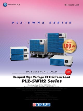
  • 1. P L Z - 5 W H 2 S E R I E S Compact High Voltage DC Electronic Load D C E L E C T R O N I C L O A D Operating voltage: 10 V to 1000 V (Min. 1.5 V) Power capacity: 1 kW/2 kW/4 kW/12 kW/20 kW, 5 models 100 kW/ 2000 A with parallel operation (Max. 5 units) Connectable with 5WH series LAN (LXI)/USB/RS232C standard digital interface *GPIB optional Synchronized operation Sequence function Arbitrary IV characteristic (ARB) mode Data-logging: voltage/current/power measurements (Measurement display, programmable internal memory) PLZ-5WH2 Series NEW Electronic Load 100kW Up to Max Power *5 Unit Parallel
  • 2. 2 High Power Density *Not including protrusions 550 (21.65") 430 (16.93") Unit: mm 13U 573.5 mm (22.58") Ideal for high capacity power supply and rechargeable battery evaluation! Testing with hyper-realistic load simulation made possible! The PLZ-5WH2 high power DC electronic load series is where durable, reliable ingenuity meets multifunctional and high power design. Providing 5 variety of power range line-ups, from 1 kW bench top style model to high power model that can sink up to 20 kW of power in a single unit. Possible to easily selects applicable power range depends on the load. Load simulation can be achieved faster than ever before thanks to the reliable, high speed design of the PLZ-5WH current control circuits. Accurate current measures can be made with extremely high setting resolution. A color LCD display allows for highly visible, user- friendly front panel operation. RS232C, USB, and LAN digital interfaces are included as standard for simple integration into any system. ● Operating voltage: 10 V to 1000 V (Min. 1.5 V) ● 20 kW capacity in a single, compact unit (PLZ20005WH2) ● Parallel operation: 5 units (Max. 100 kW/ 2000 A), Connectable with different models.* *Connectable with 5WH series. However, a firmware update is required. ● Synchronization: Load on/off control and sequence execution can be synchronized among multiple units. ● Sequence Function: Program can be saved / loaded on USB memory ● Arbitrary IV characteristic (ARB) mode ● User-friendly color LCD display ● Data logging function: voltage/current/power/elapsed time/integrated current/ integrated power measurements. (Measurement display, programmable internal memory, stored as CSV format onto a USB.) ● Superposition of sinusoidal current (Sine Function, 1 Hz to 10 kHz) ● Cutoff function: The load can be turned off when the elapsed time, the voltage drop, the integrated current, or the integrated power reaches the specified value. ● LAN (LXI)/USB/RS232C standard digital interface *GPIB optional 12 kW PLZ12005WH2 20 kW PLZ20005WH2 1 kW PLZ1005WH2 2 kW PLZ2005WH2 4 kW PLZ4005WH2 NEW Maximum Operating Voltage 1000V Compact, High Power Model Max operating current Operating voltage Power PLZ1005WH2 20 A 10 V to 1000 V 1 kW PLZ2005WH2 40 A 2 kW PLZ4005WH2 80 A 4 kW PLZ12005WH2 240 A 12 kW PLZ20005WH2 400 A 20 kW 3U 128 mm (5.04") 9U 396.2 mm (15.60") 100kW Up to Max Power *5 Unit Parallel Compact High Voltage DC Electronic Load PLZ-5WH2 Series
  • 3. 3 100 10 approx. 1.5 1000 0 1 400 100 Input voltage [V] Input current [A] 1000 Actual operating area Operating area where specifications are guaranteed 20000 W Logarithmic axis 1 50 V 400 A 1000 V 20 A ● Maximum current and power during parallel operation using the same model Model Parallel operation number Maximum current Maximum power PLZ20005WH2 2 800 A 40 kW 3 1200 A 60 kW 4 1600 A 80 kW 5 2000 A 100 kW Communication Interface LAN, USB and RS232C standard digital interface. *GPIB Option LXI compliant!! Control and monitor the power from buit-in browser! Use a browser from a PC, smartphone, or tablet to access the web server built into the PLZ-5WH2 series for convenient control and monitoring. [Recommended browser] ●Microsoft Edge 10 ●Internet Explorer version 9.0 or later ●Firefox 8.0 or later ●Safari/Mobile Safari 5.1 or later ●Chrome 15.0 or later ●Opera 11.0 or later *Connecting with a smartphone, tablet, etc. requires a Wi-Fi environment. (wireless LAN router etc.). The PLZ-5WH2 series boasts a 20 μs rise time*, easily satisfying the critical needs of power supply evaluation tests demanding a fast transient response. *When using the PLZ20005WH2 PLZ20005WH2 Slew Rate: 20 A/μs Current (100 A/DIV) Time (20 μs/DIV) 400 A 300 A 200 A 100 A Current setting Rated current Operating voltage ranges from 10 V to 1000 V. Minimum operating voltage required to sink current is 1.5 V. [Operating area of PLZ20005WH2] Operating voltage ranges 10V to 1000V Minimum operating voltage 1.5V Up to 100 kW with parallel operation (Max. 5 units) Parallel Operation Parallel operation (max. 5 units) is available on all models by simply connecting an optional parallel operation cable. This feature is available even among different models for a wide range of high power. (up to 100 kW / 2000 A) PLZ20005WH2 (5 units) PLZ1005WH2 PLZ2005WH2 PLZ4005WH2 PLZ12005WH2 PLZ20005WH2 Different model can parallel! *A parallel cable needs to have each unit connection. 12 kW and 20 kW models are included in accessory. 1 kW, 2 kW and 4 kW models are option. In ARB mode, arbitrary I-V characteristics can be set by registering multiple I-V characteristic points (pairs of voltage and current values). Three up to 100 points can be registered, and the space between two points is linearly interpolated. The minimum voltage (0.00 V) and current (0.00 A) and the maximum voltage (1010.00 V) are fixed. Arbitrary I-V Characteristics (ARB) Mode Example of setting value (* Value is fixed) Voltage[V] Current[A] 0.00* 12.00 20.50 23.00 24.50 1010.00* 0.00* 0.10 0.20 0.40 0.80 0.80 10.00 20.00 30.00 1010.00 0.20 0.40 0.60 0.80 0 0 [A] [V] I-V characteristics example Maximum Slew Rate of 20 A/μs Wide Ranging Operation Voltage up to 1000 V Parallel operation connection cable Master unit Slave unit Slave unit Slave unit Slave unit PARALLEL OUT IN PARALLEL OUT IN PARALLEL OUT IN PARALLEL OUT IN PARALLEL OUT IN ●Connection conceptual diagram 39 kW 100 kW PLZ-5WH2 series Smart High Power & [Specifications: See P.10] [Specifications: See P.12] 20 kW 12 kW 4 kW 2 kW 1 kW ×5 20 kW [Specifications: See P.9] Functions ● Parallel connection with PLZ-5WH series* Must be PLZ-5WH as a Master and update the firmware to newest version. *When parallel operation between 5WH and 5WH2, only same capacity model is available. Operation Modes Constant current (CC) mode When a current value is specified, the current is kept at that value even when the voltage changes. Constant resistance (CR) mode Whenaconductancevalueisspecified,theproductsinkscurrentproportio- naltothevoltagevariationbyusingthevalueasaproportionalityconstant. Constant voltage (CV) mode When a voltage value is specified, the product runs the current so that the voltage is kept at that value. Constant power (CP) mode When a power value is specified, the product runs the current so that the power is kept at that value. Arbitrary I-V charac- teristics (ARB) mode The desired load characteristics can be set by specifying multiple arbitrary voltage values and current values as I-V characteristics. The following five operation modes are available on the PLZ-5WH2. In addition, available to set in operation modes other than CV mode, the “UVPL*” setting keep the voltage less than UVP setting by controlling the current and the “UVPT” setting loads off by applying a current to reach the target setting voltage. [Specifications: See P.8-9] *"UVPL" is the "+CV mode" in PLZ-5W series
  • 4. 4 Functions Load On/Off The following load on/off settings are available in addition to standard operations that can be carefully adjusted to fit the needs of any test environment. ● Start with "load on" when power is turned on ● Display elapsed "load on" time ● Auto "load off" when time limit is reached ● Control "load on/off" with external controls such as relays ● "Load off" by specifying conditions (Cutoff function) Soft Start Soft start is a function that controls the rise time of the load current. Soft start functions only when all the following conditions are met. ● The rise time of the soft start has been set. ● Load on state in constant current (CC) mode. ● There is an input that is equal to or exceeds the minimum operating condition, from the state where there is no input to the load input terminals. If the load current rises sharply, the DUT output may become unstable or the DUT’s overcurrent protection circuit may be activated. In such situations, it is possible to make the load current to rise slowly only when the product is started. time 0 PLZ-5WH2 series DUT’s voltage waveform time 0 ■ When soft start has been disabled ■ When soft start has been set properly Load On Load On PLZ-5WH2 series Rise start (Current starts flowing.) PLZ-5WH2 series Rise start (Current starts flowing.) Input voltage or current Input voltage or current Operation mode CC Time setting range 500 μs, 1 ms, 2 ms, 5 ms, 10 ms, 20 ms, 50 ms, 100 ms, or off Changing the Response Speed Set the response speed for CV, CR, or ARB mode according to the DUT’s conditions and application. Item Description Response Voltage Set the response speed for CV mode. Normal, Fast Conductance Set the response speed for CR mode. Normal, Fast ARB Set the response speed for ARB mode. The value is the filter response time. Select OFF for no filter. OFF, 500 μs, 1 ms, 2 ms, 5 ms, 10 ms, 20 ms, 50 ms, 100 ms Saving Measurement Data Measurement data can be stored in CSV format to a USB memory device. Cutoff Function The cutoff function allows the user to enable load off once the elapsed time/voltage drop/integrated current/integrated power has been reached after load on. Multiple factors can be selected, with load off being implemented after the first requirement is met. Elapsed time The load turns off when the elapsed time value reaches the specified value. Voltage drop* The load turns off when the voltmeter value reaches the specified value. Integrated current The load turns off when the ampere-hour meter value reaches the specified value. Integrated power The load turns off when the watt-hour meter value reaches the specified value. [Specifications: See P.11] Integrated Data Function Time elapsed, integrated current and integrated power can be logged. Logging (integration) can be coordinated to start/finish when the load turns on/off or during the start or end of a sequence. Logging can also be controlled arbitrarily. item Value Description Integral Gate - Set the integrated data recording period. None Integrated data recording is started/stopped manually. Load On Recording is started/stopped automatically in synchronization with load on/load off. Or, recording is started or stopped manually. Program Run Recording is started/stopped automatically in synchronization with sequence execution start/stop. Or, recording is started or stopped manually. Reset - Selects the integrated data reset method. If the product is restarted, inte-grated data is reset. Manual Integrated data is reset when the Reset key is pressed. Auto Integrated data is automatically reset before the start of recordings. Or, integrated data is reset when the Reset key is pressed. Time Voltage 0 UVP detection voltage Integrated data recording Example: Integral Gate is set to Load On, and UVP is set [Specifications: See P.11] Data Logging Function The data logging function allows the user to log measurement values (current, voltage, power) in the internal memory, and display logged data on an LCD screen (Table) as a chart (Chart). By setting measurement recording conditions, you can control the timing that measurements are recorded. Condition Value Description Trigger − Set the measurement recording timing and the number of times to record measurements. Source − Event (trigger source) that defines the measurement recording condition. Recording starts after the Initiate key is pressed and a trigger is received. Immediate Pressing Initiate applies a trigger immediately. BUS Applies a trigger when a *TRG command is received from a PC or when the *TRG key on the front panel is pressed. DIGITAL2* Applies a trigger when a signal is received at pin 13 of the EXT CONT connector. MSync The trigger application timing is synced between PLZ-5WH2 that are synchronized TALink Applies a trigger when a step is executed if Generate is set to TALink in the sequence step settings Load Off Applies a trigger when the load is turned off. Count 1 to 65536 The number of times to recorded measurements. Delay 0 μs to 100 s (resolution: 10 μs) The delay time from trigger application until measurement recording. Interval Disable/Enable Sets whether to insert an interval between recordings when Count is 2 or higher. Interval Time 10 μs to 3600 s (resolution: 10 μs) Recording interval time when Interval is set to Enable. Sense Aperture 10 μs to 1 s (resolution: 10 μs) Time period of each recording. The average over the time period is recorded. *Only when Direction of Digital 2 is set to Input ▲ Data logging display example (Figure display) [Specifications: See P.9] *Voltage drop cutoff operates in the same manner as UVPT of the UVP function. UVP turns the load off based on the protection function, but the cutoff function turns the load off when the specified conditions are met. As such, there is no need to clear alarms, which is required when a UVPT is activated.
  • 5. 5 Functions Sine Function The sine function varies the current sinusoidally. It is suitable for super- posed ripple testing of large capacity power supplies and batteries. When a sine operation is in progress, a trigger signal is output from the TRIG OUT connector on the front panel. You can set this regardless of whether the load is on or off. This function operates in CC mode. You cannot set the slew rate. Set the sine amplitude with a value. When a sine operation is in progress, a trigger signal is output for 10 μs from the TRIG OUT connector on the front panel when the current passes through the Set value on the rising edge (sine wave phase at 0 degrees). 0[A] Amplitude [A] Current [A] Current Time Current: Load value (center value of the amplitude) Amplitude: Sine amplitud 0 Current Time TRIG OUT 10 µs Current Operation mode CC Frequency setting range 1 Hz to 1 kHz, 2 kHz, 5 kHz, 10 kHz Frequency setting resolution* 1 Hz to 10 Hz 1 Hz 20 Hz to 100 Hz 10 Hz 200 Hz to 1000 Hz 100 Hz 1000 Hz to 2 kHz, 5 kHz, 10 kHz * (Reference) The resolution actually set in the device is period resolution ⊿ T= 20 μs, as shown in the equation below. For example, if you specify 900 Hz, the period set in the device will be n × ⊿ T = 56 × 20 μs = 1120 μs (where n is a number set in the device). Converted to frequency, this becomes 1/1120 μs ≈ 893 Hz. Sequence Function A sequence consists of programs and steps. A program is a collection of steps. Steps are executed in order one at a time, starting from step 1. The completion of the last step signifies that the program has been executed once. When the specified number of program loops is completed, the sequence ends. You can set the load state (load on or off, load value, slew rate) at the end of the sequence of a program. Setting range Setting Description By step Load value Current, conductance, voltage, power. The values that can be set depend on the current operation mode. Slew rate Sets the speed of change when the current is changed. Step execution time 0.000050 s to 3600000 s (50 μs to 1000 h), resolution: 1 μs Load on/off control To turn the load on, set the load setting transition method to step or ramp. Other Trigger signal setting, trigger signal output For each program Number of loops of program 1 to 100000 repetitions, or infinite repetitions. Protection function Specifies the value at which a protection function (OCP, OPP, UVP) is activated. ● TALink The TALink (Transient Acquire Link) trigger makes it possible to log data in PLZ-5WH2 in synchronization with the sequence steps. Logged data can then be accessed through ommunication with the PLZ-5WH2 and saved to a USB as a CSV file. Step 1 Step 2 Step 3 Step 4 Step 5 Step 6 Step 7 Step 8 Step 9 Input current Time Measurement Loop 1 Loop 2 Set a program for each operation mode. Up to 30 programs can be set.Up to 10000 steps total can be used in all programs. Input current Step 1 Step 2 Step 3 Step 4 Time Program1 Load value Step 1 Step 2 Step 3 Step 4 Program1 Pulse function refers to the operation of executing two settings repetitively. It is suitable for transient response characteristics testing of large capacity power supplies and batteries. When the pulse operation is in progress, a trigger signal is output from the TRIG OUT connector on the front panel. You can set this regardless of whether the load is on or off. This function operates in CC and CR modes. The pulse amplitude is set with a value or a percentage of the load value. When the pulse operation is in progress, a trigger signal is output for 10 μs from the TRIG OUT connector on the front panel when the current amplitude changes from low (Depth) to high (Set) level. Pulse Function Operation mode CC and CR Frequency setting range 1.0 Hz to 10.0 kHz Frequency setting resolution* 1 Hz to 10 Hz 0.1 Hz 11 Hz to 100 Hz 1 Hz 110 Hz to 1000 Hz 10 Hz 1.1 kHz to 10.0 kHz 0.1 kHz * (Reference) The resolution actually set in the device is period resolution ⊿ T = 1 μs, as shown in the equation below. For example, if you specify 9300 Hz, the period set in the device will be n × ⊿ T = 108 × 1 μs = 108 μs (where n is a number set in the device). Converted to frequency, this becomes 1/108 μs = 9259 Hz. HIGH LOW 0 Current Time TRIG OUT 10 µs 0[A][S]( 0 % ) Depth [A][S ][%] Current [A] or Conductance [S] (100 %) Current Time Current or conductance: Load value in CC mode or CR mode Depth: Pulse level [Specifications: See P.9] Trip Turns the load off. The setting display changes to UVPT. Limit Limits the voltage so as not to become equal to or less than the set value. The setting display changes to UVPL. ●Alarm 2 (low urgency) Name Mode Activation Overcurrent protection (OCP) CR, CV, CP Load off or limit Overpower protection (OPP) CC, CR, CV, ARB Undervoltage protection (UVP) CC, CR, CP, ARB Load off, limit, or activation off Watchdog protection (WDP) All Load off ●Alarm 1 (high urgency) Name Activation Overvoltage detection (OVP) Load off Reverse-connection detection (Reverse) Overheat detection, overcurrent detection of the front-panel DC INPUT terminals (OTP/Front) Alarm input detection (External) Parallel operation anomaly detection This function limits the current (UVPL) or turns off the load (UVPT) when the voltage applied to the product becomes equal to or less than the UVP setting. You can set this regardless of whether the load is on or off. Alarm Function This function detects anomalies and protects the DUT. There are two types of alarm based on urgency level: alarm 1 (high urgency) and alarm 2 (low urgency). [Specifications: See P.10]
  • 6. 6 ABC Preset Memories Three setting values can be stored in preset memory slots A, B, and C. All saved settings can be accessed at the press of a button, which is perfect for when you want to quickly switch between three sets of values. The setup memory can store up to 20 sets (0 to 19) of the current conditions of the items listed below. The current conditions can also be saved in a USB memory device. ● Operation mode ● Load values (current, voltage, conductance, power) ● Slew rate ● Pulse amplitude (current/conductance or percentage) ● Pulse interval (frequency/time of one cycle and duty cycle/operating time on the high side) ● Sine amplitude (current) ● Sine frequency ● Alarm operating conditions ● Content of ABC preset memories A file saved on the PLZ-5WH2 can be transferred to the PLZ-5W via a USB memory device. If the UVP is set to "limit" on the PLZ-5WH2, this will be changed to +CV mode on the PLZ-5W (PLZ205W, PLZ405W, PLZ1205W). Setup Memory Current and Voltage Monitor In addition to the conventional current monitor output, voltage monitor output (0 V to 10 V/Output of 1/100 of measured voltage) has been added to the front BNC connector. Synchronized Operation The following synchronization features are available when simply connecting the PLZ-5WH2 with other equipment using a communication cable. Any of the models in the PLZ-5WH2 series can be connected together. Synchronized operation is possible even during parallel operation. ● Synchronizing load on/off among multiple pieces of equipment. ● Synchronizing measurements. ● Synchronizing the start time and resume time for sequences across multiple units. To EXT SYNC IN of another device EXT SYNC IN EXT SYNC OUT EXT SYNC OUT LAN cable [Connection example] Remote Sensing With remote sensing, the voltage measurement point can be changed from the load input terminal to the DUT sensing point. By connecting the sensing leads to the DUT, the effects of voltage drops caused by resistance in the load cables can be reduced and the operation in CR / CV / CP / ARB mode stabilized. ● Remote sensing input rated voltage: 1000 V USB Keyboard You can enter numbers/characters if you connect a keyboard to the USB port on the front panel. The types of keyboards that you can use are 101-key and 104-key keyboards. External Control The PLZ-5WH2 can be controlled and monitored from an external device. The external control terminals are isolated from the load input terminal. EXT CONT connector pin number 14 25 1 13 Rear panel [Specifications: See P.12] [Specifications: See P.12] Functions Pin no. In/Out *1 Signal name Description 1 – STATUS COM Status signal common for pins 14 to 16. 2 NC – – 3 NC – – 4 NC – – 5 IN ALARM CLEAR Alarm clearing input 6 IN ALARM INPUT Alarm input 7 NC – – 8 NC – – 9 IN TRIG INPUT Trigger input. Resumes program execution if Wait(post) was set to Trig IN in a sequence step and the program was paused. 10 – A COM This is connected to the chassis. 11 OUT DIGITAL 0 DIGITAL0 output. Sequence control possible. 12 OUT DIGITAL 1 DIGITAL1 output. Sequence control possible. 13 IN/OUT DIGITAL 2 DIGITAL2 I/O. Input/output switchable. Sequence signal output or the trigger input of sequences and measurement function. 14 OUT ALARM1 ALARM1 output. ON when overvoltage detection, reverse-con- nection detection, overheat detection, alarm input detection, or parallel operation anomaly detection is activated, and also during external alarm input. 15 OUT ALARM2 ALARM2 output. ON during OCP, OPP, UVP, or WDP operation. 16 OUT LOAD ON STATUS Load-on status output. ON during load on. 17 NC – – 18 IN LOAD ON/OFF CONT Load on/off control input. Logic level switchable. 19 – A COM This is connected to the chassis. 20 IN EXT CONT ADD External voltage control input. Controls the load setting of CC mode by adding current. 21 IN EXT CONT MODE External voltage control input. Controls the load values of CC, CR, and CP modes. 22 IN EXT CONT CV External voltage control input. Controls the voltage of CV mode. 23 – A COM This is connected to the chassis. 24 OUT IMON Current monitor output. 25 NC – – *1 1000 V reinforced insulation between each terminal and the DC INPUT terminal.
  • 7. 7 LV124 Standard L-02 Life test - high-temperature endurance test (Durability - Heat) [Life test] [Combination of AC power source and electronic load equipment] *DUT must function completely before/during/after testing (n=6 units) AC Power Supply DC Electronic Load AC 230 V DC 1000 V EUT EUT EUT EUT EUT EUT Onboard Charger ● EV Charger Aging Tests ● DC-DC Converter Evaluation DC-DC converter performance tests vital for automotive electric components can easily be carried out by controlling the converter input (DC power supply) and output (DC electronic load). The DC power supply and electronic load can be started up simultaneously for variation tests and efficiency tests. PCR-WE/WE2 Series PLZ-5WH2 Series DC Electronic Load PLZ-5WH2 Series DC Power Supply PAT Series 0- V Input voltage DC500 V 1U Multi Range Programmable DC Power Supply PWX Series DC-DC Converter Battery simulated voltage DC13.5 V Operating voltage DC10 V to 1000 V ● Battery Discharge Testing Battery discharge test can be conducted and results saved without a PC. The acquired data can be saved in CSV format on USB memory. I/V Curve (sequence) Cut conditions: Time Data display: chart Sample: 1 Volmetric property (Constant current) Cut conditions: Voltage or capacity (Ah) Data display: table Sample: 5 DC Electronic Load PLZ-5WH2 Series Battery Application
  • 8. 8 The used terminology is as follows: • TYP: These are typical values that are representative of situations where the product operates in an en vironment with an ambient temperature of 23 °C (73.4 °F). These values do not guarantee the performance of this product. • setting: Indicates a setting. • reading: Indicates a readout value.• rating: Indicates a rated value. • Open: Indicates equivalence to the state in which the DC INPUT terminals are opened. Unless specified otherwise, the specifications are for the following settings and conditions. • The product is warmed up for at least 30 minutes. • Rear-panel DC INPUT terminals are used. Specifications ■Rating Item PLZ1005WH2 PLZ2005WH2 PLZ4005WH2 PLZ12005WH2 PLZ20005WH2 Operating voltage (DC) 10 V to 1000 V Power 1000 W 2000 W 4000 W 12000 W 20000 W Current 20 A 40 A 80 A 240 A 400 A DC INPUT terminal’s isolation voltage Positive pin: ±1000 V, Negative pin: ±900 V Minimum operating voltage At the rated current 10 V When the current begins to flow 1.5 V or less ■Constant current (CC) mode Item PLZ1005WH2 PLZ2005WH2 PLZ4005WH2 PLZ12005WH2 PLZ20005WH2 Operating range 0 A to 20 A 0 A to 40 A 0 A to 80 A 0 A to 240 A 0 A to 400 A Setting range 0.0000 A to 20.2000 A 0.000 A to 40.400 A 0.000 A to 80.800 A 0.00 A to 242.40 A 0.00 A to 404.00 A Resolution 0.0005 A 0.001 A 0.002 A 0.005 A 0.01 A Setting accuracy ±(0.2 % of setting + 0.1 % of rating) Parallel operation ±(0.4 % of setting + 0.2 % of rating) ■Constant resistance (CR) mode Item PLZ1005WH2 PLZ2005WH2 PLZ4005WH2 PLZ12005WH2 PLZ20005WH2 Operating range *1 H range 500 mS to 0 S 1 S to 0 S 2 S to 0 S 6 S to 0 S 10 S to 0 S L range 5 mS to 0 S 10 mS to 0 S 20 mS to 0 S 60 mS to 0 S 100 mS to 0 S Setting range H range 505.00 mS to 0.00 S 1.01000 S to 0.00000 S 2.02000 S to 0.00000 S 6.0600 S to 0.00000 S 10.1000 S to 0.0000 S L range 5.0500 mS to 0.0000 S 10.1000 mS to 0.0000 S 20.2000 mS to 0.000 S 60.600 mS to 0.000 S 101.000 mS to 0.000 S Resolution H range 0.01 mS 0.00002 S 0.00005 S 0.0002 S 0.0002 S L range 0.0001 mS 0.0002 mS 0.0005 mS 0.002 mS 0.002 mS Setting accuracy *2 H range ±(0.5 % of setting + 0.5 % of rating *3) L range ±(0.5 % of setting + 0.2 % of rating *3) Parallel operation H range ±(1.0 % of setting + 1.0 % of rating *3) L range ±(1.0 % of setting + 0.4 % of rating *3) Response speed NORM/FAST *1. Conductance [S] = input current [A]/input voltage [V] = 1/resistance [Ω] *2. Converted value at the input current. At the sensing point during remote sensing. *3. Rated current ■Constant voltage (CV) mode Item PLZ1005WH2 PLZ2005WH2 PLZ4005WH2 PLZ12005WH2 PLZ20005WH2 Operating range 10 V to 1000 V Setting range 0.00 V to 1010.00 V Resolution 0.02 V Setting accuracy *1 ±(0.05 % of setting + 0.05 % of rating) Parallel operation ±(0.1 % of setting + 0.1 % of rating) Response speed NORM/FAST *1. With the input voltage within the operating range, and at the sensing point during remote sensing. ■Constant power (CP) mode Item PLZ1005WH2 PLZ2005WH2 PLZ4005WH2 Operating range 0 W to 1000 W 0 W to 2000 W 0 W to 4000 W Setting range 0.00 W to 1010.00 W 0.00 W to 2020.00 W 0 W to 4040.00 W Resolution 0.02 W 0.05 W 0.1 W Setting accuracy ±(0.5 % of rating *1 + 0.02 A × Vin *2) ±(0.5 % of rating *1 + 0.04 A × Vin *2) ±(0.5 % of rating *1 + 0.08 A × Vin *2) Parallel operation ±(1 % of power rating + 0.1 % current rating × Vin *2) Item PLZ12005WH2 PLZ20005WH2 Operating range 0 W to 12000 W 0 W to 20000 W Setting range 0.0000 kW to 12.1200 kW 0.0000 kW to 20.2000 kW Resolution 0.0005 kW Setting accuracy ±(0.5 % of rating *1 + 0.2 A × Vin *2) ±(0.5 % of rating *1 + 0.4 A × Vin *2) Parallel operation ±(1 % of power rating + 0.1 % current rating × Vin *2) *1. Rated power *2. DC INPUT terminal voltage or SENSING terminal voltage.
  • 9. 9 Specifications ■Arbitrary I-V characteristics (ARB) mode Item PLZ1005WH2 PLZ2005WH2 PLZ4005WH2 PLZ12005WH2 PLZ20005WH2 Operating range Three to 100 points of current values can be specified for the input voltage. Linear interpolation is applied between specified points. Response speed 500 μs, 1 ms, 2 ms, 5 ms, 10 ms, 20 ms, 50 ms, 100 ms, or off ■Measurement function Voltmeter Item PLZ1005WH2 PLZ2005WH2 PLZ4005WH2 PLZ12005WH2 PLZ20005WH2 Display 0.00 V to 1000.00 V Resolution 10 mV Accuracy ±(0.05 % of reading + 0.05 % of rating) Parallel operation ±(0.1 % of reading + 0.1 % of rating) (TYP) Ammeter Item PLZ1005WH2 PLZ2005WH2 PLZ4005WH2 PLZ12005WH2 PLZ20005WH2 Display 0.000 A to 20.000 A 0.000 A to 40.000 A 0.000 A to 80.000 A 0.00 A to 240.00 A 0.00 A to 400.00 A Resolution 0.001 A 0.001 A 0.001 A 0.01 A 0.01 A Accuracy ±(0.2 % of reading + 0.1 % of rating) Parallel operation ±(0.4 % of reading + 0.2 % of rating) (TYP) Power display Item PLZ1005WH2 PLZ2005WH2 PLZ4005WH2 PLZ12005WH2 PLZ20005WH2 Display Displays the product of the voltmeter reading and ammeter reading Measurement trigger Item PLZ1005WH2 PLZ2005WH2 PLZ4005WH2 PLZ12005WH2 PLZ20005WH2 Trigger Source Immediate, BUS, DIGITAL2, MSync, TALink, LoadOff Trigger Count 1 to 65536 Trigger Delay 0.00000 s to 100.00000 s Interval Disable/Enable Interval Time 0.00001 s to 3600 s Sense Aperture 0.00001 s to 1.00000 s ■Pulse function Item PLZ1005WH2 PLZ2005WH2 PLZ4005WH2 PLZ12005WH2 PLZ20005WH2 Operation mode CC and CR Frequency setting range 1.0 Hz to 10.0 kHz Frequency setting resolution *1 1 Hz to 10 Hz 0.1 Hz 11 Hz to 100 Hz 1 Hz 110 Hz to 1000 Hz 10 Hz 1.1 kHz to 10.0 kHz 0.1 kHz Frequency setting accuracy 1 Hz to 5.0 kHz ±(0.5 % of setting) 5.1 Hz to 10.0 kHz ±(1.0 % of setting) Duty cycle setting range, step 1 Hz to 10 Hz 5.0 % to 95.0 %, 0.1 % steps 11 Hz to 100 Hz 110 Hz to 1000 Hz 1.1 kHz to 10.0 kHz 5 % to 95 % *2, 1 % steps *1. (Reference) The resolution actually set in the device is period resolution ⊿T = 1 μs, as shown in the equation below. For example, if you specify 9300 Hz, the period set in the device will be n × ⊿T = 108 × 1 μs = 108 μs (where n is a number set in the device). Converted to frequency, this becomes 1/108 μs = 9259 Hz. *2. The minimum time span is 20 μs. The minimum duty cycle is limited by the minimum time span. Switch value (Depth) Item *1 PLZ1005WH2 PLZ2005WH2 PLZ4005WH2 PLZ12005WH2 PLZ20005WH2 CC mode 0.0000 A to 20.2000 A 0.000 A to 40.400 A 0.000 A to 80.800 A 0.000 A to 242.40 A 0.00 A to 404.00 A CR mode H range 505.00 mS to 0.00 S 1010.00 mS to 0.00 S 2020.00 mS to 0.00 S 6.06000 S to 0.00000 S 10.1000 S to 0.0000 S L range 5.0500 mS to 0.0000 S 10.1000 mS to 0.0000 S 20.2000 mS to 0.0000 S 60.600 mS to 0.000 S 101.000 mS to 0.000 S *1. The switch value is limited to the set current or set conductance or less.
  • 10. 10 ■Slew rate Item PLZ1005WH2 PLZ2005WH2 PLZ4005WH2 PLZ12005WH2 PLZ20005WH2 Operation mode CC Operating range 0.001 A/µs to 1 A/µs 0.002 A/µs to 2 A/µs 0.004 A/µs to 4 A/µs 0.01 A/µs to 12 A/µs 0.02 A/µs to 20 A/µs Resolution 0.00002 A/µs 0.00005 A/µs 0.0001 A/µs 0.0002 A/µs 0.0005 A/µs Setting accuracy *1 ±(10 % of setting +20 μs) *1. Time to change from 10 % to 90 % when the current is changed from 0 % to 100 % of the rated current ■Sine function Item PLZ1005WH2 PLZ2005WH2 PLZ4005WH2 PLZ12005WH2 PLZ20005WH2 Operation mode CC Frequency setting range 1 Hz to 1000 Hz, 2000 Hz, 5000 Hz, 10000 Hz Frequency setting resolution *1 1 Hz to 10 Hz 1 Hz 20 Hz to 100 Hz 10 Hz 200 Hz to 1000 Hz 100 Hz 1000 Hz to 2 kHz, 5 kHz, 10 kHz Frequency setting accuracy 300 Hz to 900 Hz ±(1.0 % of setting) Other than the frequencies above ±(0.5 % of setting) *1. (Reference) The resolution actually set in the device is period resolution ⊿T= 20 μs, as shown in the equation below. For example, if you specify 900 Hz, the period set in the device will be n × ⊿T = 56 × 20 μs = 1120 μs (where n is a number set in the device). Converted to frequency, this becomes 1/1120 μs ≈ 893 Hz. ■Soft start Item PLZ1005WH2 PLZ2005WH2 PLZ4005WH2 PLZ12005WH2 PLZ20005WH2 Operation mode CC Time setting range 500 μs, 1 ms, 2 ms, 5 ms, 10 ms, 20 ms, 50 ms, 100 ms, or off ■Alarm function Alarm 1 Item PLZ1005WH2 PLZ2005WH2 PLZ4005WH2 PLZ12005WH2 PLZ20005WH2 Overvoltage detection Turns off the load when a voltage that is 110 % of the rating or higher is applied. Reverse-connection detection Turns off the load when approximately -1 % of the rated current flows through the DC INPUT terminals. Overheat detection, overcurrent detection of the front-panel DC INPUT terminals Turns off the load when the heatsink temperature reaches 100 °C. Or, turns off the load when a current of 30 A or higher is flowing through the front-panel DC INPUT terminals. Alarm input detection Turns off the load when a voltage between 0 V and 1.5 V is applied to ALARM INPUT (pin 6) of the EXT CONT connector. Parallel operation anomaly detection Turns off the load when any of the following errors occurs. • An error occurred in the communication between the master unit and slave unit during parallel operation. • A slave unit’s power supply was interrupted. • A n overheating was detected on the master or slave unit. • An overcurrent flowed through the front-panel DC INPUT terminals. • PLZ-5WH series or PLZ-5W series was connected as a slave. Alarm 2 Item PLZ1005WH2 PLZ2005WH2 PLZ4005WH2 PLZ12005WH2 PLZ20005WH2 Overcurrent protection (OCP) Setting range 0.000 A to 22.000 A 0.00 A to 44.00A 0.00 A to 88.00A 0.00 A to 264.00A 0.00 A to 440.00A Resolution 0.001 A 0.01 A 0.01 A 0.01 A 0.1 A Protection operation Select load off or limit. Overpower protection (OPP) Setting range 0.0 W to 1100.0 W 0.0 W to 2200.00 W 0 W to 4400 W 0.000 W to 13.200 kW 0.000 W to 22.000 kW Resolution 0.1 W 0.1 W 1 W 0.001 kW 0.001 kW Protection operation Select load off or limit. Undervoltage protection (UVP) Setting range 0.00 V to 1000.00 V, or off. Resolution 0.02 V Protection operation Select load off or limit. Watchdog protection (WDP) Setting range 1 s to 3600 s or off Protection operation Load off ■Sequence function Item PLZ1005WH2 PLZ2005WH2 PLZ4005WH2 PLZ12005WH2 PLZ20005WH2 Operation mode CC, CR, CV, CP Maximum number of programs 30 Maximum number of steps 10000 Step execution time 0.000050 s to 3600000 s (50 µs to 1000 h) Time resolution 1 µs Specifications
  • 11. 11 ■Integration display Item PLZ1005WH2 PLZ2005WH2 PLZ4005WH2 PLZ12005WH2 PLZ20005WH2 Elapsed time display Displays the time from load on to load off. Range 0 s to 3600000 s (1000 h 0 min 0 s) Ampere-hour meter display Displays integrated current Range 0 Ah to 70000 Ah 0 Ah to 140000 Ah 0 Ah to 280000 Ah 0 Ah to 800000 Ah 0 Ah to 1400000 Ah Watt-hour meter display Displays integrated power Range 0 Wh to 40000000 Wh 0 Wh to 80000000 Wh 0 Wh to 160000000 Wh 0 Wh to 500000000 Wh 0 Wh to 800000000 Wh ■Cutoff function Item PLZ1005WH2 PLZ2005WH2 PLZ4005WH2 PLZ12005WH2 PLZ20005WH2 Elapsed time The load turns off when the elapsed time value reaches the specified value. Range 0 s to 3600000 s (1000 h 0 min 0 s) Resolution 1 s Integrated current The load turns off when the ampere-hour meter value reaches the specified value. Range 0 Ah to 70000 Ah 0 Ah to 140000 Ah 0 Ah to 280000 Ah 0 Ah to 800000 Ah 0 Ah to 1400000 Ah Resolution 0.001 mAh (0.000 mAh to 1000.000 mAh) 0.001 Ah (1.001 Ah to 1000.000 Ah) 0.001 kAh (1.001 kAh to 1 000.000 kAh) 0.001 MAh (1.001 MAh to 1.400 MAh) Integrated power The load turns off when the watt-hour meter value reaches the specified value. Range 0 Wh to 40000000 Wh 0 Wh to 80000000 Wh 0 Wh to 160000000 Wh 0 Wh to 500000000 Wh 0 Wh to 800000000 Wh Resolution 0.001 Wh (0.000 Wh to 1 000.000 Wh) 0.001 kWh (1.001 kWh to 1 000.000 kWh) 0.001 MWh (1.001 MWh to 800.000 MWh) Voltage drop The load turns off when the voltmeter value becomes less than or equal to the specified value. Range 0.00 V to 1000.00 V Resolution 0.02 V ■Other functions Item PLZ1005WH2 PLZ2005WH2 PLZ4005WH2 PLZ12005WH2 PLZ20005WH2 Remote sensing Input voltage rating *1 1000 V *2 Isolation voltage ±1000 V Number of units in parallel operation 5 units Mutual synchronized operation *3 Synchronizes load on/off. Synchronization of sequence execution, and sequence resumption. Synchronizing the recording timing of measured values. *1. There are limitations depending on the actual power that the load consumes. *2. Total potential difference between the DC INPUT terminals and SENSING terminals *3. The terminals for mutual synchronized operation are isolated from the DC INPUT terminals and operate at the chassis potential. Specifications
  • 12. 12 ■EXT CONT connector Item *1 PLZ1005WH2 PLZ2005WH2 PLZ4005WH2 PLZ12005WH2 PLZ20005WH2 Load on/off control input Logic level switchable. Pulled up to 5 V by a 10 kΩ resistor. The thresholds are HIGH: 3.5 V to 5 V, LOW: 0 V to 1.5 V. Alarm input An alarm is activated with a voltage between 0 V and 1.5 V. Pulled up to 5 V by a 10 kΩ resistor. The thresholds are HIGH: 3.5 V to 5 V, LOW: 0 V to 1.5 V. Alarm clearing input After an alarm occurs, eliminate the root cause of the alarm, and change the input to pin 5 of the EXT CONT connector from a low level signal to a high level signal. The alarm will be cleared on the rising edge of this signal. Pulled up to 5 V by a 10 kΩ resistor. The thresholds are HIGH: 3.5 V to 5.0 V, LOW: 0 V to 1.5 V. Trigger input Paused sequence operation resumes when a voltage between 0 V and 0.66 V is received. Pulled up to 5 V by a 10 kΩ resistor. The thresholds are HIGH: 2.31 V to 3.3 V, LOW: 0 V to 0.66 V. External voltage control input(CC, CR, CP mode) Controls the load settings of CC, CR, CP mode through external voltage input. Input impedance: Approx. 10 kΩ. CC: The setting can be controlled in the range of 0 % to 100 % of the rated current through external voltage input of 0 V to 10 V. CR: The setting can be controlled in the range of 0 % to 100 % of the conductance setting through external voltage input of 0 V to 10 V. CP: The setting can be controlled in the range of 0 % to 100 % of the rated power through external voltage input of 0 V to 10 V. Setting accuracy ±(1 % of rating) (TYP value in CC mode) External voltage control input (CV mode) The load setting of CV mode can be controlled through external voltage input. The rated voltage can be controlled in the range of 0 % to 100 % with 0 V to 10 V. Input impedance: Approx. 10 kΩ. Setting accuracy ±(1 % of rating) (TYP) External voltage control input (superimposing in CC mode) Controls the load setting of CC mode by adding current through external voltage input. Adds current in the range of -100 % to 100 % of the rated current for -10 V to 10 V.Input impedance: Approx. 10 kΩ. Setting accuracy ±(1 % of rating) (TYP) Load-on status output On when load is on. Open-collector output from a photocoupler. *2 ALARM 1 output ON when overvoltage detection, reverse-connection detection, overheat detection, front-panel DC INPUT overcurrent detection, alarm input detection, or parallel operation anomaly detection is activated. Open-collector output from a photocoupler. *2 ALARM 2 output Turns on when OCP, OPP, UVP, or WDP is activated. Open-collector output from a photocoupler. *2 DIGITAL 0 output Can be controlled through sequences. Output impedance: Approx. 330 Ω. The thresholds are HIGH: 2.5 V to 3.3 V, LOW: 0 V to 0.4 V. DIGITAL 1 output DIGITAL 2 input/output Input/output switchable. Output: Sequence trigger output. The output impedance is 330 Ω.The thresholds are HIGH: 2.5 V to 3.3 V, LOW: 0 V to 0.4 V. Input: Trigger input signal for the sequence and the measurement functions. The thresholds are HIGH: 2.31 V to 3.3 V, LOW: 0 V to 0.66 V Current monitor output Outputs 0 V to 10 V for 0 % to 100 % of the rated current. Output impedance: 1 kΩ (TYP). Accuracy ±(1 % of rating) (TYP) *1. 1000 V reinforced insulation between each terminal and the DC INPUT terminal *2. The maximum voltage that can be applied to the photocoupler is 30 V. The maximum current is 4 mA. ■BNC connector Item PLZ1005WH2 PLZ2005WH2 PLZ4005WH2 PLZ12005WH2 PLZ20005WH2 Trigger output Transmits 10 μs pulses during step execution when trigger output is set in a sequence. Transmits 10 μs pulses during pulse operation and sine operation. Output impedance: 200 Ω, output voltage HIGH: 4.2 V to 5.0 V, LOW: 0 V to 0.4 V. Current monitor output Output voltage Outputs 0 V to 10 V for 0 % to 100 % of the rated current Output impedance 50 Ω (TYP) Accuracy ±(1 % of rating) Voltage monitor output Output voltage Outputs the measured voltage with 1/100 magnification from 0 V to 10 V. Output impedance 50 Ω (TYP) Accuracy ±(1 % of rating) Isolation voltage ±30 V ■Communication function Item PLZ1005WH2 PLZ2005WH2 PLZ4005WH2 PLZ12005WH2 PLZ20005WH2 RS232C Hardware D-SUB 9-pin connector. Baud rate: 9600, 19200, 38400, 115200 bps. Data length: 8 bits, Stop bits: 1 bit, Parity bit: None Flow control: No, CTS/RTS Message terminator LF during reception, LF during transmission. USB (device) Hardware Standard type B socket. Complies with the USB 2.0 specification. Data rate: 480 Mbps (High Speed). Message terminator LF or EOM during reception, LF + EOM during transmission. Device class Complies with the USBTMC-USB488 device class specifications. USB (host) Hardware Standard type A socket Complies with the USB 2.0 specification. Data rate: 480 Mbps (High Speed). LAN Hardware IEEE 802,3 100Base-TX/10Base-T Ethernet IPv4, RJ-45 connector. Compliant standards LXI 1.4 Core Specification 2011 Communication protocol VXI-11, HiSLIP, SCPI-RAW, SCPI-Telnet Message terminator VXI-11, HiSLIP: LF or END during reception, LF + END during transmission. SCPI-RAW: LF during reception, LF during transmission. Specifications
  • 13. 13 ■General specifications Item PLZ1005WH2 PLZ2005WH2 PLZ4005WH2 PLZ12005WH2 PLZ20005WH2 Input voltage range 100 Vac to 240 Vac (90 Vac to 250 Vac) single phase Input frequency range 47 Hz to 63 Hz Power consumption 70 VAmax 90 VAmax 150 VAmax 360 VAmax 590 VAmax Inrush current (peak value) 100 Vac 30 Amax 30 Amax 30 Amax 40 Amax 40 Amax 230 Vac 80 Amax 80 Amax 80 Amax 160 Amax 160 Amax Leakage current *1 0.5 mA or less 0.6 mA or less 0.8 mA or less 1.6 mA or less 2.4 mA or less Environmental conditions Operating temperature range 0 °C to 40 °C (32 °F to 104 °F) Operating humidity range 20 %rh to 85 %rh (no condensation) Storage temperature range -25 °C to 60 °C (-13 °F to 140 °F) Storage humidity range 90 %rh or less (no condensation) Installation location Indoor use, altitude of up to 2000 m, overvoltage category II Insulation resistance Between primary and chassis, input, monitor terminals 1000 Vdc, 30 MΩ or more (70 %rh or less) Between input terminals and chassis, monitor terminal 1000 Vdc, 3 MΩ or more (70 %rh or less) Withstanding voltage Between primary and chassis, input, monitor terminals No abnormalities at 1500 Vac for 2 s Between input terminals and chassis, monitor terminal No abnormalities at 1500 Vac for 2 s External dimensions Refer to external dimensions Weight Approx. 13 kg (28.7 lbs) Approx. 16 kg (35.3 lbs) Approx. 20 kg (44.1 lbs) Approx. 64 kg (141.1 lbs) Approx. 93 kg (205 lbs) Accessories [Common to all models] Power cord (1 pc., length: 2.5 m), Safety terminal adapter TL41 (red 1 set, black 1set), External control connector kit (1 set), Safety Information (1 copy), Setup Guide (1 copy), Quick Reference (Japanese 1 sheet, English 1 sheet), CD-ROM (1 disc) [PLZ1005WH2, PLZ2005WH2, PLZ4005WH2] Rear-panel DC INPUT terminal cover (1 set), Screw set for rear-panel DC INPUT terminals (2 sets), Screws for the rear-panel DC INPUT terminal cover (2 pcs.) , Front-panel DC INPUT terminal cover (1 pc.), Screws for the front-panel DC INPUT terminals (2 pcs.) , Heavy object warning label (1 pc.) PLZ4005WH2 only [PLZ12005WH2, PLZ20005WH2] Rear-panel DC INPUT terminals cover (1 set), Screw set for rear-panel DC INPUT terminals (2 sets), Rear-panel DC INPUT terminals cover screws (2 pcs.), Heavy object warning label (1 pc.), Parallel operation signal cable kit [PC02-PLZ-5W] Electromagnetic compatibility (EMC) *2 *3 Complies with the requirements of the following directive and standards. EMC Directive 2014/30/EU EN 61326-1 (Class A *4), EN 55011 (Class A *4, Group 1 *5), EN 61000-3-2, EN 61000-3-3 Applicable under the following conditions The maximum length of all cabling and wiring connected to the product must be less than 3 m. Safety *2 Complies with the requirements of the following directive and standards. EMC Directive 2014/35/EU *3 EN 61010-1 (Class I *6, Pollution Degree 2 *7) *1. Leakage current between the positive and negative terminals of the rear-panel DC INPUT. At 1000 Vdc. *2. Does not apply to specially ordered or modified products. *3. Limited to models that have a CE mark on their panels. *4. This is a Class A instrument. This product is intended for use in an industrial environment. This product may cause interference if used in residential areas. Such use must be avoided unless the user takes special measures to reduce electromagnetic emissions to prevent interference to the reception of radio and television broadcasts. *5. This is a Group 1 instrument. This product does not generate and/or use intentionally radio-frequency energy, in the form of electromagnetic radiation, inductive and/or capacitive coupling, for the treatment of material or inspection/analysis purpose. *6. This is a Class I instrument. Be sure to ground this product's protective conductor terminal. The safety of this product is guaranteed only when the product is properly grounded. *7. Pollution is addition of foreign matter (solid, liquid or gaseous) that may produce a reduction of dielectric strength or surface resistivity. Pollution Degree 2 assumes that only non-conductive pollution will occur except for an occasional temporary conductivity caused by condensation. Specifications
  • 14. 14 ●PLZ1005WH2/PLZ2005WH2 ●PLZ4005WH2 429.5(16.91)(MAX455(17.91))W×128(5.04)(MAX145(5.71))H×400(15.75)(MAX540(21.26))D (mm (inch)) 429.5(16.91)(MAX440(17.32))W×128(5.04)(MAX145(5.71))H×500(19.69)(MAX640(25.2))D (mm (inch)) External Dimensions Unit: mm (inches) MAX25 (0.98) MAX540 (21.26) 400 (15.75) 8-M4 screw holes (including opposite face) (Max. screw insertion depth: 8 mm (0.31)) 27.9 (1.1) 70 (2.76) 30.1 (1.19) 22.5 (0.89) 367.5 (14.47) 40 (1.57) 429.5 (16.91) MAX10 (0.39) MAX455 (17.91) 128 (5.04) MAX145 (5.71) 360 (14.17) 344 (13.54) 34.75 (1.37) 34.75 (1.37) 42.75 (1.68) 42.75 (1.68) 55 (2.17) 323 (12.72) 4-M3 screw holes (Max. screw insertion depth: 6 mm (0.24)) 22 (0.87) 30 (1.18) (Four holes for attaching the rubber feet) 4- 5 (0.20) Unit: mm (inches) MAX25 (0.98) MAX640 (25.2) 500 (19.69) 70 (2.76) 27.9 (1.1) 30.1 (1.19) 22.5 (0.89) 467.5 (18.41) 8-M4 screw holes (including opposite face) (Max. screw insertion depth: 8 mm (0.31) 40 (1.57) 429.5 (16.91) MAX440 (17.32) 128 (5.04) MAX145 (5.71) 360 (14.17) 344 (13.54) 34.75 (1.37) 34.75 (1.37) 42.75 (1.68) 42.75 (1.68) 55 (2.17) 423 (16.65) 22 (0.87) 4-M3 screw holes (Max. screw insertion depth: 6 mm (0.24)) 4- 5 (0.20) (Four holes for attaching the rubber feet) 30 (1.18)
  • 15. 15 ●PLZ12005WH2 ●PLZ20005WH2 430(16.93)(MAX545(21.46))W×396.2(15.6)(MAX495(19.49))H×550(21.65)(MAX720(28.35))D (mm (inch)) 430(16.93)(MAX545(21.46))W×573.5(22.58)(MAX670(26.38))H×550(21.65)(MAX720(28.35))D (mm (inch)) External Dimensions Unit: mm (inches) MAX25 (0.98) 550 (21.65) 44.8 (1.76) MAX720 (28.35) 70 (2.76) 123.5 (4.86) 100 (3.94) 123.5 (4.86) 22.9 (0.9) 18 (0.71) 132.5 (5.22) 40 (1.57) 220 (8.66) 40 (1.57) 18-M4 screw holes (including opposite face) (Max. screw insertion depth: 8 mm (0.31)) 8-M10 screw holes (including opposite face) (Max. screw insertion depth: 10 mm (0.39)) 515 (20.28) 25 (0.98) 396.2 (15.6) MAX545 (21.46) 430 (16.93) MAX495 (19.49) M12 screw hole (Max. screw insertion depth: 35 mm (1.38)) 74.2 (2.92) 54 (2.13) 36 (1.42) 340 (13.39) 448 (17.64) 58.5 (2.3) 16 M6 screw holes (Max. screw insertion depth: 8 mm (0.31) Unit: mm (inches) MAX25 (0.98) 550 (21.65) 44.8 (1.76) MAX720 (28.35) 70 (2.76) 175 (6.89) 175 (6.89) 175 (6.89) 22.2 (0.87) 18 (0.71) 132.5 (5.22) 40 (1.57) 220 (8.66) 40 (1.57) 18-M4 screw holes (including opposite face) (Max. screw insertion depth: 8 mm (0.31)) 8-M10 screw holes (including opposite face) (Max. screw insertion depth: 10 mm (0.39)) 515 (20.28) 25 (0.98) 573.5 (22.58) MAX545 (21.46) 430 (16.93) MAX670 (26.38) M12 screw hole (Max. screw insertion depth: 35 mm (1.38)) 74.2 (2.92) 54 (2.13) 36 (1.42) 340 (13.39) 448 (17.64) 58.5 (2.3) 16 M6 screw holes (Max. screw insertion depth: 8 mm (0.31))
  • 16. GPIB Converter (PIA5100) This converter converts RS232C or USB of the PLZ-5WH2 to GPIB, enabling connection of a remote controller using GPIB. [Accessories: Power cord set, Magnetic sheet] [Connection example] Parallel Operation Signal Cable Kit One cable required for each slave/booster unit. Rack Mount Bracket These are rack mounting options. Model Appropriate Model Description KRB3-TOS PLZ1005WH2 PLZ2005WH2 PLZ4005WH2 For EIA inch racks KRB150-TOS For JIS millimeter racks KRB9 PLZ12005WH2 For EIA inch racks KRB400-PCR-LE For JIS millimeter racks KRB13 PLZ20005WH2 For EIA inch racks KRB600 For JIS millimeter racks PLZ5WH2 PIA5100 Remote control device DC OUT (5 V) RS232C or USB GPIB Name Model Cable length Parallel operation cable PC01-PLZ-5W Approx. 30 cm PC02-PLZ-5W* Approx. 1 m * Supplied with PLZ12005WH2 and PLZ20005WH2. High-Voltage Load Cable Coming soon This load cable supports high voltage. Up to 80 A (Kikusui-recommended current) is supported. Sequence Creation and Control Software NEW The SD033-PLZ-5WH2(Wavy for PLZ-5WH2) is an application software designed for sequence creation and operation of Kikusui’s PLZ-5WH2 series of DC electronic loads. It allows users to freely carry out sequence control of power supplies and electronic loads without any programming knowledge. Users can easily edit sequences as if drawing a picture or working on a spreadsheet. ● Able to easily create and edit sequence functions using a mouse. ● Execution positions are visually displayed during sequence execution. ● Monitors voltage and current, which can be saved into files. ● Monitor data displayed in real time as a monitor graph. Expand the ideas of engineers with the sequence creation and control software " Wavy " SD033-PLZ-5WH2 (Wavy for PLZ-5WH2) *Screen sample Wavy Series Options Printed in Japan Issue: Oct 2020 202010PDFEC11a ■ All products contained in this catalogue are equipment and devices that are premised on use under the supervision of qualified personnel, and are not designed or produced for home-use or use by general consumers. ■ Specifications, design and so forth are subject to change without prior notice to improve the quality. ■ Product names and prices are subject to change and production may be discontinued when necessary. ■ Product names, company names and brand names contained in this catalogue represent the respective registered trade name or trade mark. ■ Colors, textures and so forth of photographs shown in this catalogue may differ from actual products due to a limited fidelity in printing. ■ Although every effort has been made to provide the information as accurate as possible for this catalogue, certain details have unavoidably been omitted due to limitations in space. ■ If you find any misprints or errors in this catalogue, it would be appreciated if you would inform us. ■ Please contact our distributors to confirm specifications, price, accessories or anything that may be unclear when placing an order or concluding a purchasing agreement. ●Distributor: www.kikusui.cn Room 305,Shenggao Building , No.137,Xianxia Road, Shanghai City, China Phone : 021-5887-9067 Facsimile : 021-5887-9069 www.kikusuiamerica.com 1-310-214-0000 3625 Del Amo Blvd, Suite 160, Torrance, CA 90503 Phone : 310-214-0000 Facsimile : 310-214-0014 Southwood 4F,6-1 Chigasaki-chuo,Tsuzuki-ku,Yokohama,224-0032,Japan Phone: (+81)45-482-6353,Facsimile: (+81)45-482-6261,www.kikusui.co.jp Trial version available on website! http://www.kikusui.co.jp/ en/download/index.html Download !