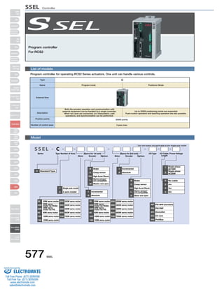
1. Program controller
For RCS2
List of models
Program controller for operating RCS2 Series actuators. One unit can handle various controls.
Type C
Name Program mode Positioner Mode
External View
Description
Number of control axes:
Model
S S E L C
Series (Specs for 1st axis) (Specs for 2nd axis)
577 SSEL
Type Number of Axes
* 2nd axis specs not applicable to the single-axis model.
Motor Encoder Option Motor Encoder Option
I/O Cable
Length
Power Voltage
I/O Type
B Brake
C Creep sensor
HA High Accel./Decel.
L Home sensor/
LS-compatible
M Master axis spec
B Brake
C Creep sensor
HA High Accel./Decel.
L Home sensor/
LS-compatible
S Slave axis spec
20 20W servo motor
30D 30W servo
motor for RCS2
30R 30W servo
motor for RS
60 60W servo motor
100 100W servo motor
150 150W servo motor
200 200W servo motor
300 300W servo motor
400 400W servo motor
600 600W servo motor
750 750W servo motor
20 20W servo motor
30D 30W servo
motor for RCS2
30R 30W servo
motor for RS
60 60W servo motor
100 100W servo motor
150 150W servo motor
200 200W servo motor
300 300W servo motor
400 400W servo motor
600 600W servo motor
750 750W servo motor
1 Single-axis model
2 2-axis model I Incremental
A Absolute
I Incremental
A Absolute
1 Single-phase
AC100V
2
Single-phase
AC200V
0 No cable
2 2m
3 3m
5 5m
NP PIO NPN (standard)
PN PIO PNP
DV DeviceNet
CC CC-Link
PR ProfiBus
C Standard Type
Both the actuator operation and communication with
external equipment can be handled by a single controller.
When two axes are connected, arc interpolation, path
operations, and synchronization can be performed.
Up to 20000 positioning points are supported.
Push-motion operation and teaching operation are also possible.
Position points 20000 points
2 axes max.
Slider
Type
Mini
Standard
Controllers
Integrated
Rod
Type
Mini
Standard
Controllers
Integrated
Table/Arm
/Flat Type
Mini
Standard
Gripper/
Rotary Type
Linear Servo
Type
Cleanroom
Type
Splash-Proof
Controllers
PMEC
/AMEC
PSEP
/ASEP
ROBO
NET
ERC2
PCON
ACON
SCON
PSEL
ASEL
SSEL
XSEL
Pulse Motor
Servo Motor
(24V)
Servo Motor
(200V)
Linear
Servo Motor
SSEL Controller
Sold & Serviced By:
ELECTROMATE
Toll Free Phone (877) SERVO98
Toll Free Fax (877) SERV099
www.electromate.com
sales@electromate.com
2. Required Number of
Regenerative Resistor Units
Vertical
~200W
1 unit
2 units
~800W ~600W
~800W
* Depending on the operating conditions,
ޓmore regenerative resistors may be needed.
SSEL 578
PLC
I/O Flat Cable (see P586)
<Model: CB-DS-PIO020>
(supplied with controller)
Field Network
Regenerative Resistor Unit
(See P585)
<Model: REU-2>
(Optional)
Panel Unit
(See P585)
<Model: PU-1>
Horizontal
0 units ~200W
Cable for Regenerative Resistor Unit
<Model: CB-SC-REU010>
(Supplied with the regenerative resistor unit.)
0.2m
Adapter Cable (see P586)
<Model: CB-SEL-SJ002>
(Optional)
3m
USB Cable (see P586)
<Model: CB-SEL-USB030>
(Supplied with the IA-101-X-USB
PC software)
Absolute Data Backup Battery (see P585)
<Model: AB-5>
(included with absolute type controller)
Teaching Pendant (see P585)
<Model: SEL-T/SEL-TD>
(Optional)
* Always use a noise filter
when connecting power
Motor Cable
<Model: CB-RCC-MA
Standard 1m/3m/5m
For a replacement cable, see P586
Encoder Cable
Model: CB-RCS2-PA
Standard 1m/3m/5m
For a replacement cable, see P586.
RS232C Cable
Model: CB-ST-E1MW050-
EB
(Supplied with the
IA-101-X-MW
PC software)
5m
5m
PC Software (see P585)
Model: IA-101-X-MW (with RS232C cable)
Model: IA-101-X-USB (with USB cable)
System Memory Backup Battery (see P585)
Actuator
RCS2 series/single-axis robot/linear servo actuator
2m
1m
3m
Model: AB-5-CS (with case)
AB-5 (standard battery)
(Optional)*1
*1ޓThe system memory backup battery is a
required feature if you wish to retain data
such as flags used in programs even after
the power has been shut off.
Main
Power
Supply Single-phase AC100V
Single-phase AC200V
Recommended: MC1220 (for AC100V) (Manufacturer: TDK-Lambda)
MC1210 (for AC200V) (Manufacturer: TDK-Lambda)
(Available through IAI. Please inquire for details.)
System configuration
Slider
Type
Mini
Standard
Controllers
Integrated
Rod
Type
Mini
Standard
Controllers
Integrated
Table/Arm
/Flat Type
Mini
Standard
Gripper/
Rotary Type
Linear Servo
Type
Cleanroom
Type
Splash-Proof
Controllers
PMEC
/AMEC
PSEP
/ASEP
ROBO
NET
ERC2
PCON
ACON
SCON
PSEL
ASEL
SSEL
XSEL
Pulse Motor
Servo Motor
(24V)
Servo Motor
(200V)
Linear
Servo Motor
SSEL Controller
Sold Serviced By:
ELECTROMATE
Toll Free Phone (877) SERVO98
Toll Free Fax (877) SERV099
www.electromate.com
sales@electromate.com
3. I/O Specifications
■ Input section External input specifications
P24V
Item
Input voltage
Input current
ON/OFF voltage
Isolation method
Specifications
DC24V ±10%
7mA / circuit
ON voltage (min.) NPN:DC16V / PNP:DC8V
OFF voltage (max.) NPN:DC5V / PNP:DC19V
Photocoupler
External
power
supply
+24V Input terminal
Inputs R=3.3kΩ
External
power
supply
+24V Input terminal
R=560Ω
Explanation of I/O Signal Functions
■ Output section External output specifications
Item
Load Voltage
Max. load current
Residual voltage (Max.)
Isolation method
Internal circuit Outputs
Outputs
Two modes can be selected for the SSEL controller: “Program Mode,” in which the actuator is operated by entering a program,
and “Positioner Mode,” in which PLC signals are received and the actuator is moved to designated positions.
The Positioner Mode has the five input patterns listed below to enable various applications.
579 SSEL
R=560Ω
Internal circuit
P24
N
Load External
power
supply
+ 2 4 V
N
Inputs R=3.3kΩ
Internal circuit P24V
N
Internal circuit
External
power
supply
+ 2 4 V
Load
NPN Specifications NPN Specifications
PNP Specifications PNP Specifications
Specifications
DC24V
100m A / 1point 400mA / 8 points in total
Max 0.1mA / 1 point
Photocoupler
■ Control Function by Type
Operation mode Features
Program mode
Positioner mode
Various operations including linear/arc interpolation operation, path operation ideal for coating processes, etc., arch-motion
operation and palletizing operation can be performed using the Super SEL language that lets you program
complex control actions using simple commands.
This is the basic mode from which operations can be conducted by designating position numbers and inputting the start
signal.
Push-motion operation and teaching operation are also possible.
Multiple parts of the same shape with slightly different hole positions can be handled using movement commands to the
same position numbers by simply changing the product type number.
With a 2-axis controller, each axis can be commanded and operated separately.
In this mode, the slider (rod) moves based on an external signal, when the actuator is stopped, the current position can
be registered as position data.
Standard mode
Product change
mode
2-axis
independent mode
Teaching mode
DS-S-C1
Compatible mode
If you were using a DS-S-C1 controller, you can replace it with a SSEL controller without having to change the host
programs. *This mode does not ensure actuator compatibility.
Slider
Type
Mini
Standard
Controllers
Integrated
Rod
Type
Mini
Standard
Controllers
Integrated
Table/Arm
/Flat Type
Mini
Standard
Gripper/
Rotary Type
Linear Servo
Type
Cleanroom
Type
Splash-Proof
Controllers
PMEC
/AMEC
PSEP
/ASEP
ROBO
NET
ERC2
PCON
ACON
SCON
PSEL
ASEL
SSEL
XSEL
Pulse Motor
Servo Motor
(24V)
Servo Motor
(200V)
Linear
Servo Motor
SSEL Controller
Sold Serviced By:
ELECTROMATE
Toll Free Phone (877) SERVO98
Toll Free Fax (877) SERV099
www.electromate.com
sales@electromate.com
4. SSEL 580
Explanation of I/O Signal Functions
Pin Number Category
Input
Output
N
Port No. Program Mode Functions
016
24V input Connect 24V.
Selects the program number to start.
(Input as BCD values to ports 016 to 022)
Resets the system to the same state as when the power is turned on.
Starts the programs selected by ports 016 to 022.
Waits for external input via program instructions.
Turns off when an alarm occurs. (Contact B)
Turns on when the controller starts up normally and is in an operable state.
These outputs can be turned ON/OFF as desired via program instructions.
Connect 0V.
0V 24
Wiring Diagram
1A P24
1B
2A
2B
3A
3B
4A
4B
5A
5B
6A
6B
7A
7B
8A
8B
9A
9B
10A
10B
11A
11B
12A
12B
13A
13B
14A
14B
15A
15B
16A
16B
17A
17B
017
018
019
020
021
022
023
000
001
002
003
004
005
006
007
008
009
010
011
012
013
014
015
300
301
302
303
304
305
306
307
Select Program No. 1
Select Program No. 2
Select Program No. 4
Select Program No. 8
Select Program No. 10
Select Program No. 20
Select Program No. 40
CPU reset
Start
General-purpose input
General-purpose input
General-purpose input
General-purpose input
General-purpose input
General-purpose input
General-purpose input
General-purpose input
General-purpose input
General-purpose input
General-purpose input
General-purpose input
General-purpose input
General-purpose input
General-purpose input
Alarm
Ready
General-purpose output
General-purpose output
General-purpose output
General-purpose output
General-purpose output
General-purpose output
0V input
Pin Number Category
Input
Output
N
Port No. Positioner
016
Note: This is for NPN. PNP will be different.
Standard Mode Functions
24V input Connect 24V.
Specifies the position numbers to move to, using port number 007 to 019
The number can be specified either as BCD or binary.
−
−
−
Resets minor errors. (Severe errors require a restart.)
Starts moving to selected position.
Performs home return.
Switches between Servo ON and OFF.
Performs a push motion.
Pauses the motion when turned OFF, and resumes motion when turned ON.
Stops the motion when turned OFF. The remaining motion is canceled.
When this signal is turned ON for a 2-axis model, the actuator moves by linear interpolation.
Specifies the position numbers to move to, using ports 007 to 019.
The number can be specified either as BCD or binary.
Turns off when an alarm occurs. (Contact B)
Turns on when the controller starts up normally and is in an operable state.
Turns on when the movement to the destination is complete.
Turns on when the home return operation is complete.
Turns on when servo is ON.
Turns on when a push motion is complete.
Turns on when the system battery runs low (warning level).
Turns on when the battery for the absolute encoder runs low (warning level).
Connect 0V.
0V 24
Wiring Diagram
1A P24
1B
2A
2B
3A
3B
4A
4B
5A
5B
6A
6B
7A
7B
8A
8B
9A
9B
10A
10B
11A
11B
12A
12B
13A
13B
14A
14B
15A
15B
16A
16B
17A
17B
017
018
019
020
021
022
023
000
001
002
003
004
005
006
007
008
009
010
011
012
013
014
015
300
301
302
303
304
305
306
307
Position input 10
Position input 11
Position input 12
Position input 13
Position input 14
Position input 15
Position input 16
Error reset
Start
Home Return
Servo ON
Push
Pause
Cancel
Interpolation setting
Position input 1
Position input 2
Position input 3
Position input 4
Position input 5
Position input 6
Position input 7
Position input 8
Position input 9
Alarm
Ready
Positioning complete
Home Return complete
Servo ON output
Pushing complete
System battery error
Absolute encoder battery error
0V input
Program mode
Positioner mode
Note: This is for NPN. PNP will be different.
Slider
Type
Mini
Standard
Controllers
Integrated
Rod
Type
Mini
Standard
Controllers
Integrated
Table/Arm
/Flat Type
Mini
Standard
Gripper/
Rotary Type
Linear Servo
Type
Cleanroom
Type
Splash-Proof
Controllers
PMEC
/AMEC
PSEP
/ASEP
ROBO
NET
ERC2
PCON
ACON
SCON
PSEL
ASEL
SSEL
XSEL
Pulse Motor
Servo Motor
(24V)
Servo Motor
(200V)
Linear
Servo Motor
SSEL Controller
Sold Serviced By:
ELECTROMATE
Toll Free Phone (877) SERVO98
Toll Free Fax (877) SERV099
www.electromate.com
sales@electromate.com
5. Explanation of I/O Signal Functions
Positioner, Product-Type Change Mode
Pin Number Category
Input
Output
N
Positioner, 2-axis Independent Mode
581 SSEL
Port No. Positioner Product
016
Type Change Mode Functions
24V input Connect 24V.
Specifies the position numbers to move to, and the product type
numbers, using ports 007 to 022.
The position and product type numbers are assigned by parameter
settings. The number can be specified either as BCD or binary.
Starts moving to selected position.
Performs home return.
Switches between Servo ON and OFF.
Performs a push motion.
Pauses the motion when turned OFF, and resumes motion when turned ON.
Stops the motion when turned OFF. The remaining motion is canceled.
When this signal is turned ON for a 2-axis model, the actuator moves by linear interpolation.
Specifies the position numbers to move to, and the product type numbers,
using ports 007 to 022.
The position and product type numbers are assigned by parameter settings.
The number can be specified either as BCD or binary.
Connect 0V.
0V 24
Wiring Diagram
1A P24
Resets minor errors. (Severe errors require a restart.)
Turns off when an alarm occurs. (Contact B)
Turns on when the controller starts up normally and is in an operable state.
Turns on when the movement to the destination is complete.
Turns on when the home return operation is complete.
Turns on when servo is ON.
Turns on when a push motion is complete.
Turns on when the system battery runs low (warning level).
Turns on when the battery for the absolute encoder runs low (warning level).
1B
2A
2B
3A
3B
4A
4B
5A
5B
6A
6B
7A
7B
8A
8B
9A
9B
10A
10B
11A
11B
12A
12B
13A
13B
14A
14B
15A
15B
16A
16B
17A
17B
017
018
019
020
021
022
023
000
001
002
003
004
005
006
007
008
009
010
011
012
013
014
015
300
301
302
303
304
305
306
307
Position/Product Type Input 10
Position/Product Type Input 11
Position/Product Type Input 12
Position/Product Type Input 13
Position/Product Type Input 14
Position/Product Type Input 15
Position/Product Type Input 16
Error reset
Start
Home Return
Servo ON
Push
Pause
Cancel
Interpolation setting
Position/Product Type Input 1
Position/Product Type Input 2
Position/Product Type Input 3
Position/Product Type Input 4
Position/Product Type Input 5
Position/Product Type Input 6
Position/Product Type Input 7
Position/Product Type Input 8
Position/Product Type Input 9
Alarm
Ready
Positioning complete
Home Return complete
Servo ON output
Pushing complete
System battery error
Absolute encoder battery error
0V input
Pin Number Category
Input
Output
N
Port No. Positioner
016
Note: This is for NPN. PNP will be different.
Independent Mode Functions
24V input Connect 24V.
Specifies the position numbers to move to, using ports 010 to 022.
The position numbers on the 1st and 2nd axes are assigned by
parameter settings.
The number can be specified either as BCD or binary.
Starts the movement to the selected position number on the 1st axis.
Performs Home Return on the 1st axis.
Switches between servo ON and OFF for the 1st axis.
Pauses the motion on 1st axis when turned OFF, and resumes when turned ON.
Cancels the movement on the 1st axis.
Starts the movement to the selected position number on the 2nd axis.
Performs Home Return on the 2nd axis.
Switches between servo ON and OFF for the 2nd axis.
Pauses the motion on 2nd axis when turned OFF, and resumes when turned ON.
Cancels the movement on the 2nd axis.
Specifies the position numbers to move to, using ports 010 to 022.
The position numbers on the 1st and 2nd axes are assigned by
parameter settings.
The number can be specified either as BCD or binary.
Connect 0V.
0V 24
Wiring Diagram
1A P24
Resets minor errors. (Severe errors require a restart.)
Turns off when an alarm occurs. (Contact B)
Turns on when the controller starts up normally and is in an operable state.
Turns on when the movement to the specified position on the 1st axis is complete.
Turns on when home return on the 1st axis is complete.
Turns on when the 1st axis is in a servo ON state.
Turns on when the movement to the specified position on the 2nd axis is complete.
Turns on when home return on the 2nd axis is complete.
Turns on when the 2nd axis is in a servo ON state.
1B
2A
2B
3A
3B
4A
4B
5A
5B
6A
6B
7A
7B
8A
8B
9A
9B
10A
10B
11A
11B
12A
12B
13A
13B
14A
14B
15A
15B
16A
16B
17A
17B
017
018
019
020
021
022
023
000
001
002
003
004
005
006
007
008
009
010
011
012
013
014
015
300
301
302
303
304
305
306
307
Position input 7
Position input 8
Position input 9
Position input 10
Position input 11
Position input 12
Position input 13
Error reset
Start 1
Home Return 1
Servo ON 1
Pause 1
Cancel 1
Start 2
Home Return 2
Servo ON 2
Pause 2
Cancel 2
Position input 1
Position input 2
Position input 3
Position input 4
Position input 5
Position input 6
Alarm
Ready
Positioning complete 1
Home Return complete 1
Servo ON output 1
Positioning complete 2
Home Return complete 2
Servo ON output 2
0V input
Note: This is for NPN. PNP will be different.
Slider
Type
Mini
Standard
Controllers
Integrated
Rod
Type
Mini
Standard
Controllers
Integrated
Table/Arm
/Flat Type
Mini
Standard
Gripper/
Rotary Type
Linear Servo
Type
Cleanroom
Type
Splash-Proof
Controllers
PMEC
/AMEC
PSEP
/ASEP
ROBO
NET
ERC2
PCON
ACON
SCON
PSEL
ASEL
SSEL
XSEL
Pulse Motor
Servo Motor
(24V)
Servo Motor
(200V)
Linear
Servo Motor
SSEL Controller
Sold Serviced By:
ELECTROMATE
Toll Free Phone (877) SERVO98
Toll Free Fax (877) SERV099
www.electromate.com
sales@electromate.com
6. SSEL 582
Explanation of I/O Signal Functions
Positioner, Teaching Mode
Pin Number Category
Input
Output
N
016
24V input Connect 24V.
While the signal is input, the 1st axis is moved in the - (negative) direction.
While the signal is input, the 2nd axis is moved in the + (positive) direction.
While the signal is input, the 2nd axis is moved in the - (negative) direction.
Specifies how much to move during inching.
(Total of the values specified for ports 019 to 022)
Port No. Positioner
Teaching Mode Functions
Starts moving to selected position.
Switches between Servo ON and OFF.
Pauses the motion when turned OFF, and resumes motion when turned ON.
Ports 003 to 013 are used to specify the position number to move, and
the position number for inputting the current position.
When the teaching mode setting on port 014 is in the ON state, the
current value is written to the specified position number.
While the signal is input, the 1st axis is moved in the plus direction.
Connect 0V.
0V 24
Wiring Diagram
1A P24
Resets minor errors. (Severe errors require a restart.)
Turns off when an alarm occurs. (Contact B)
Turns on when the controller starts up normally and is in an operable state.
Turns on when the movement to the destination is complete.
Turns on when the home return operation is complete.
Turns on when servo is ON.
Turns on when the system battery runs low (warning level).
Turns on when the battery for the absolute encoder runs low (warning level).
1B
2A
2B
3A
3B
4A
4B
5A
5B
6A
6B
7A
7B
8A
8B
9A
9B
10A
10B
11A
11B
12A
12B
13A
13B
14A
14B
15A
15B
16A
16B
17A
17B
017
018
019
020
021
022
023
000
001
002
003
004
005
006
007
008
009
010
011
012
013
014
015
300
301
302
303
304
305
306
307
JOG− on 1st axis
JOG+ on 2nd axis
JOG− on 2nd axis
Specify inching (0.01mm)
Specify inching (0.1mm)
Specify inching (0.5mm)
Specify inching (1mm)
Error reset
Start
Servo ON
Pause
Position input 1
Position input 2
Position input 3
Position input 4
Position input 5
Position input 6
Position input 7
Position input 8
Position input 9
Position input 10
Position input 11
Teaching mode setting
JOG+ on 1st axis
Alarm
Ready
Positioning complete
Home Return complete
Servo ON output
System battery error
Absolute encoder battery error
0V input
Positioner, DS-S-C1 Compatible Mode
Pin Number Category
Input
Output
N
016
24V input Connect 24V.
Note: This is for NPN. PNP will be different.
(Same as ports 004 through 015)
Port No. Positioner DS-S-C1
Compatible Mode Functions
Starts moving to selected position.
Pauses the motion when turned ON, and resumes motion when turned OFF.
Stops the motion when turned ON. The remaining motion is canceled.
When this signal is turned ON for a 2-axis model, the actuator moves by linear interpolation.
Ports 004 through 016 are used to specify the position number to move.
The numbers are specified as BCD.
Connect 0V.
0V 24
Wiring Diagram
1A P24
Resets the system to the same state as when the power is turned on.
Turns off when an alarm occurs. (Contact A)
Turns on when the controller starts up normally and is in an operable state.
Turns on when the movement to the destination is complete.
Turns on when the system battery runs low (warning level).
Turns on when the battery for the absolute encoder runs low (warning level).
1B
2A
2B
3A
3B
4A
4B
5A
5B
6A
6B
7A
7B
8A
8B
9A
9B
10A
10B
11A
11B
12A
12B
13A
13B
14A
14B
15A
15B
16A
16B
17A
17B
017
018
019
020
021
022
023
000
001
002
003
004
005
006
007
008
009
010
011
012
013
014
015
300
301
302
303
304
305
306
307
Position No. 1000
Position No. 2000
Position No. 4000
Position No. 8000
Position No. 10000
Position No. 20000
NC (*1)
CPU reset
Start
Hold (Pause)
Cancel
Interpolation setting
Position No. 1
Position No. 2
Position No. 4
Position No. 8
Position No. 10
Position No. 20
Position No. 40
Position No. 80
Position No. 100
Position No. 200
Position No. 400
Position No. 800
Alarm
Ready
Positioning complete
System battery error
Absolute encoder battery error
0V input
(*1) The input needs to be set to OFF. Be sure to leave this disconnected.
Note: This is for NPN. PNP will be different.
Slider
Type
Mini
Standard
Controllers
Integrated
Rod
Type
Mini
Standard
Controllers
Integrated
Table/Arm
/Flat Type
Mini
Standard
Gripper/
Rotary Type
Linear Servo
Type
Cleanroom
Type
Splash-Proof
Controllers
PMEC
/AMEC
PSEP
/ASEP
ROBO
NET
ERC2
PCON
ACON
SCON
PSEL
ASEL
SSEL
XSEL
Pulse Motor
Servo Motor
(24V)
Servo Motor
(200V)
Linear
Servo Motor
SSEL Controller
Sold Serviced By:
ELECTROMATE
Toll Free Phone (877) SERVO98
Toll Free Fax (877) SERV099
www.electromate.com
sales@electromate.com
7. Table of specifications
Item Specifications
Connected actuator
Input Voltage
Power Supply Capacity
Dielectric strength voltage
Withstand voltage
Rush current
Vibration resistance
Number of control axes
Maximum total output of connected axis
Position detection method
Speed setting
Acceleration setting
Operating method
Programming language
Number of programs
Number of program steps
Number of multi-tasking programs
Positioning Points
Data memory device
Data input method
Number of I/O
I/O power
PIO cable
Serial communications function
Field Network
Motor Cable
Encoder cable
Protection function
Ambient operating humidity and temperature
Ambient atmosphere
Protection class
Weight
External dimensions
External Dimensions
SSEL 1-axis controller
583 SSEL
RCS2 series actuator / single axis robot / linear servo actuator
Single-phase AC90V to AC126.5V
Single-phase AC180V to AC253V
Max. 1660VA (for 400W, 2-axis operation)
DC500V 10MΩ or higher
AC500V 1 min.
Control Power 15A / Motor Power 37.5A Control Power 30A / Motor Power 75A
XYZ directions 10 to 57Hz, One side amplitude: 0.035mm (continuous), 0.075mm (intermittent)
58 to 150 Hz 4.9 m/s2 (continuous), 9.8 m/s2 (intermittent)
1 axis / 2 axis
400W 800W
Incremental encoder / Absolute encoder
1mm/sec and up, the maximum depends on actuator specifications
0.01G and up, the maximum depends on the actuator
Program operation / Positioner operation (switchable)
Super SEL language
128 programs
9999 steps
8 programs
20000 points
FLASHROM (A system-memory backup battery can be added as an option)
Teaching pendant or PC software
24 input points / 8 output points (NPN or PNP selectable)
Externally supplied 24VDC ± 10%
CB-DS-PIO □□□ (supplied with the controller)
RS232C (D-Sub Half-pitch connector) / USB connector
DeviceNet, CC-Link, ProfiBus
CB-ACS-MA □□□ (Max. 20m)
CB-RCP2-PA □□□ (Max. 20m)
Motor overcurrent, Motor driver temperature check, Overload check, Encoder open-circuit check
Soft limit over, system error, battery error, etc.
0 to 40°C 10 to 95% (non-condensing)
Free from corrosive gases. In particular, there shall be no significant dust.
IP20
1.4kg
100mm (W) x 202.6mm (H) x 126mm (D)
(Note 1)
(Note 1) Absolute data back-up battery. Not installed with
incremental specification.
SSEL 2-axis controller
(Note 1)
(Note 1) Absolute data back-up battery. Not installed with
incremental specification.
Basic Specifications
Control
specification
Communication Program
General
specifications
Slider
Type
Mini
Standard
Controllers
Integrated
Rod
Type
Mini
Standard
Controllers
Integrated
Table/Arm
/Flat Type
Mini
Standard
Gripper/
Rotary Type
Linear Servo
Type
Cleanroom
Type
Splash-Proof
Controllers
PMEC
/AMEC
PSEP
/ASEP
ROBO
NET
ERC2
PCON
ACON
SCON
PSEL
ASEL
SSEL
XSEL
Pulse Motor
Servo Motor
(24V)
Servo Motor
(200V)
Linear
Servo Motor
SSEL Controller
Sold Serviced By:
ELECTROMATE
Toll Free Phone (877) SERVO98
Toll Free Fax (877) SERV099
www.electromate.com
sales@electromate.com
8. 15 Brake switch for axis 1
This switch is used to release the axis brake. Setting it to
the left position (RLS side) forcibly releases the brake,
while setting it to the right position (NOM side) causes the
controller to automatically control the brake.
SSEL 584
Name of Each Part
$#6 $#6
5$#6
2 System I/O connector
Connector for emergency stop / enable input / brake power
input, etc.
11 Grounding screw
Protective grounding screw. Always ground this screw.
12 External regenerative resistor connector
A connector for the regenerative resistor that must be
connected when the built-in regenerative resistor alone
does not offer sufficient capacity in high-acceleration/
high-load operation, etc.
Whether or not an external regenerative resistor is
necessary depends on the conditions of your specific
application such as the axis configuration.
13 Motor connector for axis 1
Connects the motor cable of the axis 1 actuator.
14 Motor connector for axis 2
Connects the motor cable of the axis 2 actuator.
16 Brake switch for axis 2
This switch is used to release the axis brake. Setting it to
the left position (RLS side) forcibly releases the brake,
while setting it to the right position (NOM side) causes the
controller to automatically control the brake.
17 Encoder connector for axis 1
Connect the encoder cable of the axis 1 actuator.
18 Encoder connector for axis 2
Connect the encoder cable of the axis 2 actuator.
19 Absolute-data backup battery connector for axis 1
A connector for the battery that backs up absolute data for
axis 1 when the actuator uses an absolute encoder.
20 Absolute-data backup battery connector for axis 2
A connector for the battery that backs up absolute data for
axis 2 when the actuator uses an absolute encoder.
21 System-memory backup battery connector
A connector for the system-memory backup battery.
3 Teaching pendant connector
A half-pitch I/O 26-pin connector that connects a teaching
pendant when the running mode is MANU. A special
conversion cable is needed to connect a conventional
Dsub, 25-pin connector.
4 Mode switch
This switch is used to specify the running mode of the
controller. The left position indicates the MANU (manual
operation) mode, while the right position indicates the
AUTO (automatic operation) mode. Teaching can only be
performed as manual operation, and automatic operation
using external I/Os is not possible in the MANU mode.
5 USB connector
A connector for PC connection via USB. If the USB
connector is connected, the TP connector is disabled and
all communication inputs to the TP connector are cut off.
6 I/O Connector
A connector for interface I/Os.
34-pin flat cable connector for DIO (24IN/8OUT) interface.
I/O power is also supplied to the controller via this
connector (Pin No. 1 and No. 34).
7 Panel unit connector
A connector for the panel unit (optional) that displays the
controller status and error numbers.
8 Absolute data backup battery
When an absolute-type axis is operated, this battery retains
position data even after the power is cut off.
9 System memory backup battery (Option)
This battery is needed if you wish to retain various data
recorded in the SRAM of the controller even after the
power is cut off.
This battery is optional. Specify it if necessary.
10 Power supply connector
AC power connector. Divided into the control power input
and motor power input.
1 Status indicator LEDs
These LEDs are used to indicate the operating condition of
the controller.
The LED status indicators are as follows:
PWR : Power is input to controller.
RDY : The controller is ready to perform program
operation.
ALM : The controller is abnormal.
EMG : An emergency stop is actuated and the drive
source is cut off.
SV1 : The axis 1 actuator servo is on.
SV2 : The axis 2 actuator servo is on.
11
12
13
15
16
14
17
18
1 9
10
8
2
3
4
5
6
7
19
20
8
9
21
Slider
Type
Mini
Standard
Controllers
Integrated
Rod
Type
Mini
Standard
Controllers
Integrated
Table/Arm
/Flat Type
Mini
Standard
Gripper/
Rotary Type
Linear Servo
Type
Cleanroom
Type
Splash-Proof
Controllers
PMEC
/AMEC
PSEP
/ASEP
ROBO
NET
ERC2
PCON
ACON
SCON
PSEL
ASEL
SSEL
XSEL
Pulse Motor
Servo Motor
(24V)
Servo Motor
(200V)
Linear
Servo Motor
SSEL Controller
Sold Serviced By:
ELECTROMATE
Toll Free Phone (877) SERVO98
Toll Free Fax (877) SERV099
www.electromate.com
sales@electromate.com
9. Option
Teaching Pendant
A teaching device for entering programs
and positions, test runs, and monitoring.
Model Description
IA-101-X-MW-J (with RS232C cable + adapter cable)
SEL-T option
585 SSEL
Specifications
39.0
Item SEL-T-J SEL-TD-J
3-position Enable Switch No Yes
Compliant
SEL-T-J
SEL-TD-J
Standard type with adapter cable
Deadman's switch type and
adapter cable
5m
Adapter cable: CB-SEL-SJ002
0.2m
66.6
46.9
55.0
89.6
218.3
110.0
• Wall-mounting
hook
Model HK-1
• Strap
Model STR-1
PC Software (Windows Only)
A startup support software for entering programs/positions, performing
test runs, and monitoring. More functions have been added for
debugging, and improvements have been made to shorten the start-up
time.
IA-101-X-MW (with RS232C cable)
5m 0.2m
Adapter cable:
RS232C Cable
CB-ST-E1MW050-EB
PC Software (CD) CB-SEL-SJ002
IA-101-X-USB (with USB cable)
3m
Compatible controller
SSEL-C
Dummy plug
DP-3
PC Software (CD)
USB cable
CB-SEL-USB030
Note:
Compliant
Only versions 6.0.0.0 and later can be used
with the SSEL controller.
Features
Model/Price
Configuration
Features
Model
Configuration
Model
Configuration
ANSI/UL standards
CE mark
Display
Ambient Operating
Temp./Humidity
Protective structure
Weight
Non-compliant
20 char. × 4 lines
0~40ºC 10~90% RH (non-condensing)
IP54
Approx. 0.4kg (not incl. cable)
Panel Unit
Display device that shows the error code from
the controller or the currently running program
number.
PU-1 (Cable length: 3m)
ø3.2 17
114
43
Horizontal
Vertical
175
Absolute Data Backup Battery System Memory Backup Battery
Battery for saving absolute data, when
operating an actuator with an absolute encoder.
Same as the battery used for system memory
backup.
AB-5
This battery is required, for example, when you
are using global flags in the program and you
want to retain your data even after the power
has been turned OFF.
AB-5-CS
AB-5
(with case)
(Standalone battery)
Features
Model
Features
Model
Features
Model
A unit that converts the regenerative current, generated during the
acceleration/deceleration of the of the motor, into heat.
In the table on the right, check the total power output of the actuator to see if a
regenerative resistor is needed.
REU-2 (for SCON/SSEL)
Features
Model
Specifications
Weight of main unit
Main unit-Controller
Connection Cable (included)
0.9kg
CB-SC-REU010 (for SSEL)
Required Number of Units Exterior Dimensions
0 units ~200W
~200W
* Depending on the operating conditions,
ޓmore regenerative resistors may be needed.
ø5
16.6 126
34
5
195
186
Regenerative Resistor Unit
Standard Price
Internal regenerative resistance 220Ω 80W
1 unit
2 units
~800W ~600W
~800W
* If 2 regenerative units are needed,
acquire one REU-2 and one REU-1
(See P596).
Slider
Type
Mini
Standard
Controllers
Integrated
Rod
Type
Mini
Standard
Controllers
Integrated
Table/Arm
/Flat Type
Mini
Standard
Gripper/
Rotary Type
Linear Servo
Type
Cleanroom
Type
Splash-Proof
Controllers
PMEC
/AMEC
PSEP
/ASEP
ROBO
NET
ERC2
PCON
ACON
SCON
PSEL
ASEL
SSEL
XSEL
Pulse Motor
Servo Motor
(24V)
Servo Motor
(200V)
Linear
Servo Motor
SSEL Controller
Sold Serviced By:
ELECTROMATE
Toll Free Phone (877) SERVO98
Toll Free Fax (877) SERV099
www.electromate.com
sales@electromate.com
10. USB Cable Adapter Cable
When you need spare parts after purchasing the product, such as when replacing a cable, refer to the list of models below.
Signal Color Wire
Pink
Purple
White
Blue/red
Orange/White
Green/White AWG26
Ground
Blue
Black
Yellow
Green
Brown
No.
5 4
2 1
3
6
9 8 7
10
11
12
13
14
A A
B
Z B
Z
LS+
FG
SD
SD
BAT−
VCC
GND
LS-BAT+
No. Signal Color Wire
AWG26
AWG26
SSEL 586
Option
Spare parts
Wire
AWG26
(soldered)
No.
10
11
12
13
26
25
24
23
9
18
19
5 4
2 1
3
6
8 7
14
15
16
17
20
21
22
Signal
E24V
0V
LS
CREEP
OT
RSV
A+
A−
B+
B−
Z+
Z−
SRD-SRD+
BAT+
BAT−
VCC
BKR-GND
BKR+
Color
Gray/White
Brown/White
Pink
Purple
White
Blue/red
Orange/White
Green/White
Blue
Orange
Black
Yellow
Green
Pin No. Color Wire
Flat
cable
crimped
Wire
Flat
cable
crimped
Pin No. Color
1A Brown 1 9B Gray 2
Motor cable/Motor robot cable
(Front view) (Front view)
Min. bend radius r = 50 mm or larger (when movable type is used)
* Only the robot cable is to be used in a cable track.
Encoder cable/Encoder robot cable
(41) (14)
Encoder cable/Encoder robot cable for RCS2-RT6/RT6R/RT7R/RA13R
1B 1A
17B 17A
(20) (10)
(15)
10
(25)
10
1
LS side
Flat cable AWG28 (34-core)
2m
No connector
1B
2A
2B
3A
3B
4A
4B
5A
5B
6A
6B
7A
7B
8A
8B
9A
Red 1
Orange 1
Yellow 1
Green 1
Blue1
Purple 1
Gray 1
White 1
Black 1
Brown-2
Red 2
Orange 2
Yellow 2
Green 2
Blue 2
Purple 2
10A
10B
11A
11B
12A
12B
13A
13B
14A
14B
15A
15B
16A
16B
17A
17B
White 2
Black 2
Brown-3
Red 3
Orange 3
Yellow 3
Green 3
Blue 3
Purple 3
Gray 3
White 3
Black 3
Brown-4
Red 4
Orange 4
Yellow 4
4
1
I/O Flat Cable
Model CB-DS-PIO □□□
* Enter the cable length (L) into □□□ . Compatible to a maximum of 10 meters.
Ex.: 080 = 8 m
Dummy Plug
When connecting the SSEL controller to a
computer with a USB cable, this plug is
inserted in the teaching port to shut off the
enable circuit.
(Supplied with the PC software IA-101-X-USB)
A cable for connecting the controller to the
USB port to a computer.
A controller with no USB port (e.g. XSEL) can
be connected to the USB port of a computer
by connecting an RS232C cable to the USB
cable via a USB adapter.
DP-3 (See PC software IA-101-X-USBMW)
CB-SEL-USB030 (Cable length: 3㨙)
An adapter cable to connect the D-sub
25-pin connector from the teaching pendant
or a PC to the teaching connector (half-pitch)
of the SSEL controller.
CB-SEL-SJ002 (Cable length: 0.2㨙)
Features
Model
Features
Model
Features
Model
Model CB-RCC-MA □□□ / CB-RCC-MA □□□ -RB
* Enter the cable length (L) into □□□ . Compatible to a maximum of 30 meters.
Ex.: 080 = 8 m
L
Controller side
1
4
Wire Color Signal
0.75sq
Green PE 1
Signal Color Wire
0.75sq
(crimped)
1 U Red
Mechanical side
(16)
(ø9)
(21)
(18)
(41)
Red
White
Black
U
V
W
2
3
4
2
3
4
V
W
PE
White
Black
Green
Model CB-RCS2-PA □□□ / CB-X3-PA □□□
* Enter the cable length (L) into □□□ . Compatible to a maximum of 30 meters.
Ex.: 080 = 8 m
1
9
1
13
14
26
18
L
Ground wire and shield braiding Gray
Red
(crimped)
Orange
15
16
17
18
BK−
BK+
The shield is connected to the hood by a clamp.
Brown/White
Gray/White
Brown
Gray
Red
(ø10)
Controller side
(13)
(37)
(Front view) Mechanical side (Front view)
Model CB-RCS2-PLA □□□ / CB-X2-PLA □□□
* Enter the cable length (L) into □□□ . Compatible to a maximum of 30 meters.
Ex.: 080 = 8 m
Ground wire and shield braiding
(crimped)
AWG26
(soldered)
10
1 A White/Blue
Wire Color Signal No.
No. Signal Color Wire
The shield is connected to the hood by a clamp.
(The wire color White/Blue indicates the colors of the band and insulation.)
(crimped)
1 E24V White/Orange
1
9
1
13
14
26
18
L
6
(ø10)
Controller side Mechanical side
(13)
(41) (14)
(37)
(Front view)
(8)
(15)
(18)
(25)
White/Orange
White/Green
Brown/Blue
Brown/Yellow
Brown/Red
Brown/Black
White/Blue
White/Yellow
White/Red
White/Black
White/Purple
White/Gray
Orange
Green
Purple
Gray
Red
Black
Blue
Yellow
E24V
0V
LS
CREEP
OT
RSV
A+
A−
B+
B−
Z+
Z−
SRD+
SRD−
BAT+
BAT−
VCC
GND
BKR−
BKR+
11
12
13
26
25
24
23
9
18
19
12345678
14
15
16
17
20
21
22
23456
23456789
10
11
12
13
14
15
16
17
18
0V
LS
CREEP
OT
RSV
ABBZZ
FG
SD
SD
BAT+
BAT−
VCC
GND
BK−
BK+
White/Green
Brown/Blue
Brown/Yellow
Brown/Red
Brown/Black
White/Yellow
White/Red
White/Black
White/Purple
White/Gray
Ground
Orange
Green
Purple
Gray
Red
Black
Blue
Yellow
Min. bend radius r = 50 mm or larger (when movable type is used)
* Only the robot cable is to be used in a cable track.
Min. bend radius r = 50 mm or larger (when movable type is used)
* Only the robot cable is to be used in a cable track.
Slider
Type
Mini
Standard
Controllers
Integrated
Rod
Type
Mini
Standard
Controllers
Integrated
Table/Arm
/Flat Type
Mini
Standard
Gripper/
Rotary Type
Linear Servo
Type
Cleanroom
Type
Splash-Proof
Controllers
PMEC
/AMEC
PSEP
/ASEP
ROBO
NET
ERC2
PCON
ACON
SCON
PSEL
ASEL
SSEL
XSEL
Pulse Motor
Servo Motor
(24V)
Servo Motor
(200V)
Linear
Servo Motor
SSEL Controller
Sold Serviced By:
ELECTROMATE
Toll Free Phone (877) SERVO98
Toll Free Fax (877) SERV099
www.electromate.com
sales@electromate.com