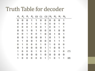
This document describes a keypad scanner circuit with 3 columns and 4 rows that is able to detect which key is pressed and output a 4-bit binary number corresponding to the key. It includes a block diagram, truth table, and Verilog code for the scanner. When a valid key is detected, the circuit will output a signal for one clock cycle. Potential applications of the keypad scanner include mobile phones, calculators, ATMs, and telephones.


![Verilog Code
• module scanner (R, CLK,C,N, V);
• input [3:0] R;
• input CLK;
• inout [2:0] C;
• output [3:0]N;
• reg C0_tmp, C1_tmp, C2_tmp;
• assign C[0] = C0_tmp;
• assign C[1] = C1_tmp;
• assign C[2] = C2_tmp;
• assign K = R[0] | R[1] | R[2] | R[3] ;
• assign N[3] = (R[2] & ~C[0]) | (R[3] & ~C[1]) ;
• assign N[2] = R[1] | (R[2] & C[0]) ;
• assign N[1] = (R[0] & ~C[0]) | (~R[2] & C[2]) | (~R[1] & ~R[0] & C[0]) ;
• assign N[0] = (R[1] & C[1]) | (~R[1] & C[2]) | (~R[3] & ~R[1] & ~C[1]) ;
• endmodule](https://image.slidesharecdn.com/keypadscannervlsi-200520194046/85/Keypad-scanner-using-Verilog-code-in-VLSI-Systems-6-320.jpg)