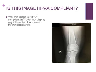
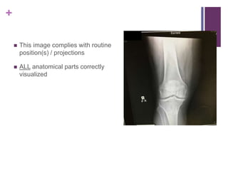
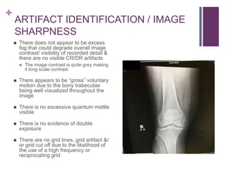
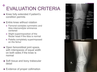
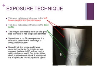
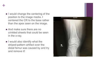
+
AP KNEE
PAIGE KAUFFMAN
+
IS THIS IMAGE HIPAA COMPLIANT?
 Yes, this image is HIPAA
compliant as it does not display
any information that violates
HIPAA compliancy.
+
MARKER & PATIENT ID
 The correct anatomical side marker is
placed on the lateral side making it
appear on the viewer’s left in relation
to the part
 The marker was placed beside the
anatomical part prior to the exposure
 The anatomical marker correctly marks
the side being imaged
 The marker is not superimposing any
pertinent anatomy
 There are no additional markers
needed/ used for this image
 Could use “weight bearing” markers if
knee was ordered weight bearing
 Based on the marker placement the
image is correctly displayed
+
RADIATION HYGIENE
 Proper beam restriction requires the
presence of at least three sides of
collimation on the image
 There are at least three sides of beam
restriction present
 Black boarder
 There is evidence to prove primary
shielding was used because there is
collimation on the side closest to the
gonads
 I shielded the patient
 Gonadal shielding must be provided if
gonads are within 5 cm of the
primary beam
+
ROUTINE RADIOGRAPHIC
PROJECTION PERFORMED:
 AP
 45 degree Oblique
 Medial rotation
 Lateral rotation
 Lateral
 mediolateral
Other Projections May Include:
• Cross Table Lateral “Shoot Thru”
• Tangential “Sunrise” Method
• Knees AP Weight – Bearing
• Knees PA Weight – Bearing, Rosenberg
• Intercondylar Fossa
• PA Axial Holmblad
• PA Axial Camp-Coventry
• AP Axial Beciere
** Projections differ based on
institutional / departmental protocls
+
 This image complies with routine
position(s) / projections
 ALL anatomical parts correctly
visualized
+
ARTIFACT IDENTIFICATION
 There appears to be an artifact
on the medial side of the knee
along with a striped-pattern over
the distal femur
 No body parts superimposed that
should not be
 There appears to be hospital
paraphernalia ( crinkled bed
sheet)
 There appears to be no
indwelling artifacts/ foreign
bodies visible
+
ARTIFACT IDENTIFICATION / IMAGE
SHARPNESS
 There does not appear to be excess
fog that could degrade overall image
contrast/ visibility of recorded detail &
there are no visible CR/DR artifacts
 The image contrast is quite grey making
it long scale contrast
 There appears to be “gross” voluntary
motion due to the bony trabeculae
being well visualized throughout the
image
 There is no excessive quantum mottle
visible
 There is no evidence of double
exposure
 There are no grid lines, grid artifact &/
or grid cut off due to the likelihood of
the use of a high frequency or
reciprocating grid
+
** Grids should be used w/ body
parts that measure more the 10cm
 Avg knee measures 9-13 cm, where non-grid or gird technique
can be employed
 Dependent upon patient knee size, radiographer/ physician
preference, department protocol
 Bontrager:
 Non-grid for smaller patients, with knees measuring 10cm or less
 Grid for larger patients, with knees measuring 10cm or more
+
IMAGE SHARPNESS
 Size distortion does not appear greater
than expected
 The CR should enter 1cm (1/2 inch)
below the patellar apex
 Off-centering is ≤1 cm –
shape distortion is
minimal
 Correct centering, alignment, CR
location = important to avoid shape /
size distortion
 Narrow joint spaces clearly demonstrated
 CR angle improves visualization of joint
spaces
+
Visualization of Joint Space
 To ensure CR is parallel to tibial plateau, & to visualize an open
joint space, measure distance between ASIS to table top to
determine CR angle …
 Angle is varied depending on the measurement
 <19 cm 3-5 degrees CAUDAD
 Thin patient
 19-24 cm 0 degrees
 Average patient
 > 25 cm 3-5 degrees CEPHALAD
 Thicker patient
+
ACCUARATE PART POSITIONING
 The part is adequately aligned to the
longitudinal axis of the imaging media
 The part is not centered to the image
media
 The CR is not centered within 1 cm of
the anatomical part
 The CR is not adequately aligned with
the image media due to the irregular
amounts of beam restriction used
 The CR’s alignment does conform to
an accepted IR exposure field
recognition template / field
+
POSITIONING
 IR Size: 10 x 12 inch, lengthwise
 40 in SID
 Place patient in the supine
position, and adjust the body so
that the pelvis is not rotated
+
Positioning
 With the IR under the patients knee, flex the joint slightly, locate
the apex of the patella and as the patient extends the knee,
center the IR about ½ inch below the patellar apex. This
centers the IR to the joint space
 Adjust the patients leg by placing the femoral epicondyles
parallel with the IR for a true AP projection. The patella lies
slightly off center to the medial side
 If the knee cannot be fully extended, a curved IR may be used
 SHIELD GONADS
 Collimate to 10 X 12 inch
+
EVALUATION CRITERIA
 Knee fully extended if patient’s
condition permits
 Entire knee without rotation
 Femoral condyles symmetric and
tibia intercondylar eminence
centered
 Slight superimposition of the
fibular head if the tibia is normal
 Patella completely superimposed
on the femur
 Open femorotibial joint space,
with interspaces of equal width
on both sides if the knee is
normal
 Soft tissue and bony trabecular
detail
 Evidence of proper collimation
+ IMAGE EVALUATION
 Knee fully extended ✔
 Entire knee without rotation ✔
 Femoral condyles symmetrical ✔
 Tibia intercondylar eminence centered ✔
 Slight superimposition of the fibular head ✔
 Open femorotibial joint space, with
interspace of equal width on both sides ✔
 Soft tissue & bony trabecular detail ✔
 Evidence of collimation ✔
IS THE ANATOMICAL PART CORRECTLY POSITIONED?
YES
+
EXPOSURE TECHNIQUE
 The most radiolucent structure is the soft
tissue margins and the joint space
 The most radiopaque structure is the bony
cortex
 The images contrast is more on the grey
side therefore it has long scale contrast
 Since there is no EI value present it is
difficult to determine if the image is
adequately exposed
 Since I took the image and it was
accepted by the techs, it is in normal
range of the hospital EI values, and is
adequately exposed !! But it should be
short scale contrast (black & white) and
the image looks more long scale (grey)
+
ACCEPT OR REJECT?
 This image meets the standards
for acceptance criteria but the
striped pattern artifact over the
distal femur is concerning!
 It is of diagnostic quality
 I would / did accept this image
 No repeat necessary, however I
would change ..
+
 I would change the centering of the
position to the image media. I
centered the CR to the base rather
than the apex seen on the image.
 And make sure there are no
crinkled sheets that could be seen
in the x-ray.
 I would also identify what the
striped-pattern artifact over the
distal femur was caused by and try
and remove it!
+
REFRENCES
 Frank, E. D., Long, B. W., Smith, B. J., & Merrill, V. (2012).
Merrill's atlas of radiographic positioning & procedures. St.
Louis, MO: Elsevier/Mosby.
 McQuillen-Martensen, K. (2015). Radiographic image
analysis. St. Louis, MO: Elsevier Saunders.
 Picture: BY ME @ Nazareth Hospital

Kauffman ap knee

  • 1.
  • 2.
    + IS THIS IMAGEHIPAA COMPLIANT?  Yes, this image is HIPAA compliant as it does not display any information that violates HIPAA compliancy.
  • 3.
    + MARKER & PATIENTID  The correct anatomical side marker is placed on the lateral side making it appear on the viewer’s left in relation to the part  The marker was placed beside the anatomical part prior to the exposure  The anatomical marker correctly marks the side being imaged  The marker is not superimposing any pertinent anatomy  There are no additional markers needed/ used for this image  Could use “weight bearing” markers if knee was ordered weight bearing  Based on the marker placement the image is correctly displayed
  • 4.
    + RADIATION HYGIENE  Properbeam restriction requires the presence of at least three sides of collimation on the image  There are at least three sides of beam restriction present  Black boarder  There is evidence to prove primary shielding was used because there is collimation on the side closest to the gonads  I shielded the patient  Gonadal shielding must be provided if gonads are within 5 cm of the primary beam
  • 5.
    + ROUTINE RADIOGRAPHIC PROJECTION PERFORMED: AP  45 degree Oblique  Medial rotation  Lateral rotation  Lateral  mediolateral Other Projections May Include: • Cross Table Lateral “Shoot Thru” • Tangential “Sunrise” Method • Knees AP Weight – Bearing • Knees PA Weight – Bearing, Rosenberg • Intercondylar Fossa • PA Axial Holmblad • PA Axial Camp-Coventry • AP Axial Beciere ** Projections differ based on institutional / departmental protocls
  • 6.
    +  This imagecomplies with routine position(s) / projections  ALL anatomical parts correctly visualized
  • 7.
    + ARTIFACT IDENTIFICATION  Thereappears to be an artifact on the medial side of the knee along with a striped-pattern over the distal femur  No body parts superimposed that should not be  There appears to be hospital paraphernalia ( crinkled bed sheet)  There appears to be no indwelling artifacts/ foreign bodies visible
  • 8.
    + ARTIFACT IDENTIFICATION /IMAGE SHARPNESS  There does not appear to be excess fog that could degrade overall image contrast/ visibility of recorded detail & there are no visible CR/DR artifacts  The image contrast is quite grey making it long scale contrast  There appears to be “gross” voluntary motion due to the bony trabeculae being well visualized throughout the image  There is no excessive quantum mottle visible  There is no evidence of double exposure  There are no grid lines, grid artifact &/ or grid cut off due to the likelihood of the use of a high frequency or reciprocating grid
  • 9.
    + ** Grids shouldbe used w/ body parts that measure more the 10cm  Avg knee measures 9-13 cm, where non-grid or gird technique can be employed  Dependent upon patient knee size, radiographer/ physician preference, department protocol  Bontrager:  Non-grid for smaller patients, with knees measuring 10cm or less  Grid for larger patients, with knees measuring 10cm or more
  • 10.
    + IMAGE SHARPNESS  Sizedistortion does not appear greater than expected  The CR should enter 1cm (1/2 inch) below the patellar apex  Off-centering is ≤1 cm – shape distortion is minimal  Correct centering, alignment, CR location = important to avoid shape / size distortion  Narrow joint spaces clearly demonstrated  CR angle improves visualization of joint spaces
  • 11.
    + Visualization of JointSpace  To ensure CR is parallel to tibial plateau, & to visualize an open joint space, measure distance between ASIS to table top to determine CR angle …  Angle is varied depending on the measurement  <19 cm 3-5 degrees CAUDAD  Thin patient  19-24 cm 0 degrees  Average patient  > 25 cm 3-5 degrees CEPHALAD  Thicker patient
  • 12.
    + ACCUARATE PART POSITIONING The part is adequately aligned to the longitudinal axis of the imaging media  The part is not centered to the image media  The CR is not centered within 1 cm of the anatomical part  The CR is not adequately aligned with the image media due to the irregular amounts of beam restriction used  The CR’s alignment does conform to an accepted IR exposure field recognition template / field
  • 13.
    + POSITIONING  IR Size:10 x 12 inch, lengthwise  40 in SID  Place patient in the supine position, and adjust the body so that the pelvis is not rotated
  • 14.
    + Positioning  With theIR under the patients knee, flex the joint slightly, locate the apex of the patella and as the patient extends the knee, center the IR about ½ inch below the patellar apex. This centers the IR to the joint space  Adjust the patients leg by placing the femoral epicondyles parallel with the IR for a true AP projection. The patella lies slightly off center to the medial side  If the knee cannot be fully extended, a curved IR may be used  SHIELD GONADS  Collimate to 10 X 12 inch
  • 15.
    + EVALUATION CRITERIA  Kneefully extended if patient’s condition permits  Entire knee without rotation  Femoral condyles symmetric and tibia intercondylar eminence centered  Slight superimposition of the fibular head if the tibia is normal  Patella completely superimposed on the femur  Open femorotibial joint space, with interspaces of equal width on both sides if the knee is normal  Soft tissue and bony trabecular detail  Evidence of proper collimation
  • 16.
    + IMAGE EVALUATION Knee fully extended ✔  Entire knee without rotation ✔  Femoral condyles symmetrical ✔  Tibia intercondylar eminence centered ✔  Slight superimposition of the fibular head ✔  Open femorotibial joint space, with interspace of equal width on both sides ✔  Soft tissue & bony trabecular detail ✔  Evidence of collimation ✔ IS THE ANATOMICAL PART CORRECTLY POSITIONED? YES
  • 17.
    + EXPOSURE TECHNIQUE  Themost radiolucent structure is the soft tissue margins and the joint space  The most radiopaque structure is the bony cortex  The images contrast is more on the grey side therefore it has long scale contrast  Since there is no EI value present it is difficult to determine if the image is adequately exposed  Since I took the image and it was accepted by the techs, it is in normal range of the hospital EI values, and is adequately exposed !! But it should be short scale contrast (black & white) and the image looks more long scale (grey)
  • 18.
    + ACCEPT OR REJECT? This image meets the standards for acceptance criteria but the striped pattern artifact over the distal femur is concerning!  It is of diagnostic quality  I would / did accept this image  No repeat necessary, however I would change ..
  • 19.
    +  I wouldchange the centering of the position to the image media. I centered the CR to the base rather than the apex seen on the image.  And make sure there are no crinkled sheets that could be seen in the x-ray.  I would also identify what the striped-pattern artifact over the distal femur was caused by and try and remove it!
  • 20.
    + REFRENCES  Frank, E.D., Long, B. W., Smith, B. J., & Merrill, V. (2012). Merrill's atlas of radiographic positioning & procedures. St. Louis, MO: Elsevier/Mosby.  McQuillen-Martensen, K. (2015). Radiographic image analysis. St. Louis, MO: Elsevier Saunders.  Picture: BY ME @ Nazareth Hospital