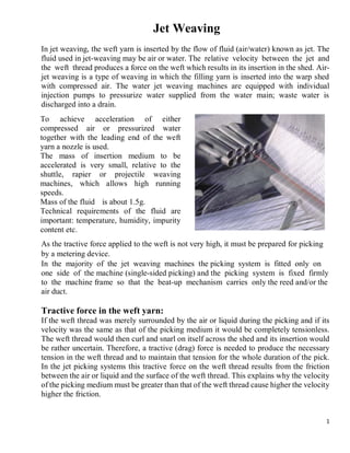
SlideShare a Scribd company logo
1 of 20
Download to read offline
1
Jet Weaving
In jet weaving, the weft yarn is inserted by the flow of fluid (air/water) known as jet. The
fluid used in jet-weaving may be air or water. The relative velocity between the jet and
the weft thread produces a force on the weft which results in its insertion in the shed. Air-
jet weaving is a type of weaving in which the filling yarn is inserted into the warp shed
with compressed air. The water jet weaving machines are equipped with individual
injection pumps to pressurize water supplied from the water main; waste water is
discharged into a drain.
As the tractive force applied to the weft is not very high, it must be prepared for picking
by a metering device.
In the majority of the jet weaving machines the picking system is fitted only on
one side of the machine (single-sided picking) and the picking system is fixed firmly
to the machine frame so that the beat-up mechanism carries only the reed and/or the
air duct.
Tractive force in the weft yarn:
If the weft thread was merely surrounded by the air or liquid during the picking and if its
velocity was the same as that of the picking medium it would be completely tensionless.
The weft thread would then curl and snarl on itself across the shed and its insertion would
be rather uncertain. Therefore, a tractive (drag) force is needed to produce the necessary
tension in the weft thread and to maintain that tension for the whole duration of the pick.
In the jet picking systems this tractive force on the weft thread results from the friction
between the air or liquid and the surface of the weft thread. This explains why the velocity
of the picking medium must be greater than that of the weft thread cause higher the velocity
higher the friction.
To achieve acceleration of either
compressed air or pressurized water
together with the leading end of the weft
yarn a nozzle is used.
The mass of insertion medium to be
accelerated is very small, relative to the
shuttle, rapier or projectile weaving
machines, which allows high running
speeds.
Mass of the fluid is about 1.5g.
Technical requirements of the fluid are
important: temperature, humidity, impurity
content etc.
2
The level of friction developed in a flowing medium is dependent on the followings:
 The square of the velocity difference,
 The viscosity of the medium as well as temperature of the medium
(Viscosity ↑ Tractive force ↑).
 The roughness and length of the weft thread.
 In the water jet insertion systems, the wetting property of the weft yarn.
The higher the viscosity the higher the tractive force. As the viscosity of the air is very low,
high relative velocities must be used in the air jet picking systems. Viscosity is largely
dependent on the temperature of the medium. For example, the viscosity of water at 00
C is
0.017 gm∕cm ∕s while at 100 0
C it is as low as 0.0028 gm ∕cm∕s. In the jet picking systems
the tractive force on the weft thread is the higher the rougher the surface of the weft
yarn. Considering the low viscosity of the employed picking medium, air-jet picking
systems are designed mainly for the spun weft weaving. However, they have become
suitable to insert filament yarns with some developments in main nozzle design.
Types of jet weaving:
Air jet weaving:
Air jet weaving is a type of weaving in which the weft yarn is inserted into the warp shed
with compressed air.
The air-jet weaving machine combines high performance with low manufacturing
requirements. It has an extremely high weft insertion rate. Due to its exceptional
performance, air-jet machines are used primarily for the economical production of
standard fabrics, covering a wide range of styles. Meanwhile, more and more special
Jet weaving
Air jet
Single nozzle
with confuser
guides and
suction unit
Multiple
nozzles with
air guides
Multiple
nozzles with
profiled reed
Water jet
3
fabrics are also covered: heavy cotton fabrics such as denim, terry fabrics, glass fabrics,
tire cord etc.
Invention:
In 1914, Brooks took the first attempt to use compressed air stream instead of shuttle. In
1929, Bollou took out a patent which incorporated a suction device at the receiving side.
First commercial machine was “Maxbo Murata” based on Maxbo Paaeboes design.
Advantages and disadvantages of air jet weaving machine:
Advantages:
 High productivity
 Low initial expenses
 High WIR
 Simple operation and reduced hazard because of few moving parts
 Reduced space requirements
 Low noise and vibration levels
 Low spare parts requirement
 Reliability and minimum maintenance
Disadvantage:
 Due to air resistance there form pile up and buckle tip of yarn
 Double pick may occurred
 Excess air pressure of main nozzle cause miss pick or broken pick.
 Loose pick
 Snarling
 Excess dynamic pressure
 Weft stop problem
 Tip problem
 Timing of shed may not be proper
 Too high or too low main nozzle pressure
 Left side (weft yarn insertion side) warp yarn is loose.
Large width of fabric can not be produced in air jet loom cause:
 The yarn become hairy.
 Weft yarn become untwisted specially in case of open end yarn.
 Yarn can be curl and the controlling of straightening of the weft yarn is difficult.
4
Timing Diagram:
Insertion configurations of air-jet weaving:
Three different systems have been used mainly on commercial air-jet weaving machines:
1. Single nozzle, confusor guides and suction unit at the exit side
2. Multiple nozzles with guides
3. Multiple nozzles with profiled reed
Although all three systems have been used in commercial looms, the configuration
system 3 is the most common and standard configuration in the market.
The main nozzle applies the necessary driving force to initiate the insertion of
predetermined length of weft yarn. The air jet flying in a free space becomes mixed with
the environmental air and loses its velocity on a relatively short distance. Hence the
integrity of the air is preserved by either a confusor or a tunnel (profiled) reed. Buckling of
the leading end of the weft is prevented by applying a constraint at the insertion side of the
machine and by maintaining the projection velocity by a series of back-up jets. This system
is precisely timed and back-up nozzles are progressively opened.
Figure: Typical timing diagram of an air-jet loom with multi-nozzles and profiled reed.
5
System-1: Single nozzle, confusor guides and suction unit at the exit side
In system 1, a single nozzle is used to insert the yarn. Air jet guide ducts (also known as
confusor) is formed by a series of ribs (flat metal plates). They are located on the race-
board in front of the reed across the entire width and penetrate between the warp ends
during the picking. The confusor keeps the initial concentration of the air as much as
possible. The leading end of the weft is stretched by a suction device.
6
System-2: Multiple nozzles with guide
System-3: Multiple nozzles with profiled reed
Figure: Single nozzle, confusor guides and
suction system.
The disadvantage of this system is the
weaving width limitation due to the
lack of additional back-up nozzles to
keep the air (and yarn) velocity high
enough across the fabric width. Air
duct is conically expanded in the
picking direction so that air molecules
in the outer fringes of the jet can be
deflected back into the main stream.
In addition to the main nozzles and air
guide ducts, auxiliary nozzles are also
used. They are arranged across the warp
width at certain intervals and they
inject (blow) the air sequentially in
groups in the direction of weft yarn
movements. The main nozzle consumes
only a small fraction of the compressed
air used in air-jet weaving machines as
compared to relay nozzles.
Figure: Multiple nozzles with guide
system.
Figure: Multiple nozzle with profiled reed.
7
Required properties of the air (air quality) in air-jet weaving:
Moisture:
 Moisture in liquid form must be eliminated.
 Vaporized moisture should be eliminated whenever possible.
 Dew point should be below 10°C. Moisture is removed from air by the process of
cooling.
Improper elimination of moisture will cause:
 Corrosion on metallic parts.
 Adhesion of foreign materials on inner walls of piping thus creating obstruction
towards airflow. It also tends to produce pin-holes on the wall of piping which
cause air-leakage.
 Degrading the quality of fabrics.
Oil: Aerosol form and vapor form must be eliminated by oil remover. Improper treatment
will cause:
 Corrosion on metal surface.
 Adhesion of foreign materials on inner side of piping cause of clog nozzles.
 Stain on fabrics.
 Problems of environmental conditions as well as health.
In this system, profiled reed wires are used
and the weft yarn is fed in to the reed tunnel
via the main nozzle. The main nozzle
(sometimes the main and tandem nozzle
combination) provides the initial
acceleration, where the relay nozzles provide
high air velocity across the shed. Profiled
reed provides guidance for the air
stream and separates the weft yarn from
warp sheets. Relay nozzles are located at
certain intervals, say 50 mm, however, last
four nozzles at the exit side are spaced
closer, say 25 mm. Additional nozzles
increase the air consumption.
Figure: Multiple nozzle with profiled
reed system.
In this system, the entrance and exit of the lamellae in and out of the shed are eliminated.
Thus, abrasion on the warp ends is reduced and misplacement of the warp ends between
lamellae, which may cause fabric defects, is prevented. With the profiled reed, the
restriction on warp density is also less severe than the case of the confusor guide system.
8
Dust: Dust particles larger than five microns must be eliminated. This is done by filtering
the incoming air. Improper treatment will cause:
 Choking and blocking of nozzles and inaccurate valve action
 Serious hazards mixed with oil and moisture.
The air-jet weaving machines are supplied with compressed air maintained from a central
source. And to supply purified air the preparation of the air is done before its distribution
by filtering, cooling, compressing, drying etc.
Operating Principle of Air-jet weaving:
The yarn is pulled from the supply package at a constant speed, which is regulated by the
rollers, located with the measuring disk just in front of the yarn package. The measuring
disk removes a length of yarn appropriate to the width of the fabric being woven. A clamp
holds the yarn in an insertion storage area, where an auxiliary air nozzle forms it into the
shape of a hairpin. The main nozzle begins blowing air so that the yarn is set in motion as
soon as clamp opens. The hairpin shape is stretched out as the yarn is blown into the guiding
channel of the reed with the shed open. The yarn is carried through the shed by the air
currents emitted by the relay nozzles along the channel. The initial propulsive force is
provided by a main nozzle. Electronically controlled relay nozzles provide additional
booster jets to carry the yarn across the shed. At the end of the each insertion cycle the
Figure: Operating principle of air-jet weaving.
9
clamp closes; the yarn is beaten in, and then cut, after the shed is closed. Again some
selvage-forming device is required to provide stability to the edges of the fabric.
Equation of tractive (propelling) force by air jet:
The total force on a body placed in a stream of fluid consists of skin friction and the integral
of normal forces. The sum of the two is called total or profile drag. The propelling force to
move the yarn in air-jet insertion is provided by friction between the air and yarn surface
and is given by the following formula:
Ff = 0.5 Cf ρ (U-V)²(𝝿dL)
Here, Ff = Propelling force along yarn axis
Cf = Surface friction co-efficient
ρ = Air density
U = Air velocity
V = Yarn velocity
d = Yarn diameter
L = Yarn length on which the fluid stream is acting
This force is proportional to the square of the relative velocity between the air and yarn.
The propulsive force increases with an increase in the air velocity and the yarn diameter.
This is because with increasing diameter, the yarn surface area that is in contact with the
air becomes larger. The dimensionless coefficient Cf is a function of Reynolds number. In
the case of compressible fluids, they also depend on Mach number. Surface friction
coefficient for spun yarns and thick yarns (with a certain hairiness) is higher than that for
fine and smooth yarns. For untreated cotton yarns the Cf is twice that of singed cotton yarns.
For textured yarns, Cf varies depending on the openness of the yarn structure.
Yarn structure, surface characteristics, hairiness, manufacturing method, twist level,
whether single or ply, texturing etc. greatly influence the propelling force of the yarn in
air-jet weaving.
Types of relay nozzle:
Figure: Multi-holes and single hole
relay nozzle.
With the main nozzle, relay nozzles are
used in the air-jet weaving to get expected
weft velocity. Auxiliary nozzles are placed
across the machine width on the loom.
Approximately 80% of the compressed air
used in an air-jet weaving machine is used
by the relay nozzles. A relay nozzle can
have a single hole or multiple holes
arranged in the direction of yarn flight. A
multi-hole relay nozzle is also called a
shower nozzle. Cross-section of the hole in
relay nozzle may be in shape of circle,
porous, rectangle, ellipse, star etc.
10
It is reported that the convex shape (C type) of the relay nozzle top may prevent warp
damages in special cases such as in filament warp weaving by avoiding splitting of the
yarn. For dull fibers or filaments always coated nozzle is used.
For a more even filling insertion, the opening of the relay nozzles is tapered. This tapered
outlet has a bundling effect on the air-jet and thus air pressure increase 30% up to 50 mm
distance. Otherwise the blowing angle with tapered relay nozzles remain constant which
helps in good flow of jet.
Otherwise a nozzle is used at the opposite of picking side (right side) called stretch nozzle
to prevent the looseness of filling yarn. It holds the filling by air to eliminate any slack
pick.
Methods of air jet control (Injection air timing of relay nozzle):
Figure: Relay nozzle tops.
Figure: Relay nozzle with tapered
opening.
Figure: Relay injection system. Figure: Injection air timing of relay nozzle.
11
Weft yarn tension during insertion:
Yarn tension affects the filling insertion by hindering the yarn movement. Yarn velocity
depends to a large extent on its tension. During the insertion, high tension causes longer
insertion times, hence lower yarn velocities. Resulting from the high air pressure, high
tensions also cause weak yarns to break. Therefore, it is desirable to even out the tension
fluctuations during insertion. Several factors determine the yarn tension on the filling yarn:
friction between the yarn and still air (before the nozzle), mechanical friction between the
yarn and guides, and air-friction force on the yarn inside the insertion channel.
Factors affects the insertion time of jet:
The factors which affect the yarn insertion are the air velocity at the main nozzle, the air
velocity distribution along the guide channel, the yarn structure and the conditions behind
the main nozzle.
Insertion time depends on the following parameters:
• Yarn structure
• Yarn surface characteristics (lubrication, finishing, etc.)
• Yarn texturing
• Yarn linear density
• Yarn twist and ply
• Yarn surface area subject to air
• Relative velocity of the air and yarn
To increase the yarn velocity, the air friction force should be increased and the tension
which hinders the yarn motion should be decreased. To increase the air friction force, air
velocity should be increased. For this, closed tubes will be ideal which will also reduce the
air consumption.
Air-jet machines can handle both spun (natural, synthetic or blended) yarns and continuous
filament yarns. Textured yarns are especially suitable for air-jet weaving due to high
propelling force. Monofilament yarns are not suitable for air-jet weaving because of low
friction between air and yarn which is due to smooth surface of the monofilament yarn. A
wide range of fabrics from gauze fabrics to dense, heavy cotton fabrics, from patterned
dress fabrics to ribbon fabrics can be woven on air-jet weaving machines. Air-jet weaving
is also ideal for fine glass fabric production. Specially designed air-jet weaving machines
are used for tire cord manufacturing with tuck-in selvage in plain weave. Since the force
required to move the yarn mass is provided exclusively by air friction against the yarn
surface, it is largely dependent on the yarn structure, the yarn and fiber surface and relative
motion of air and yarn. The propulsive force is largely independent of the fiber material.
The air consumption of the main jet depends on the yarn type and denier. Spun yarns and
coarse yarns (with a certain hairiness) have higher air resistance coefficients than fine and
smooth materials. This explains why monofilament yarns cannot be inserted with air-jet.
The factors that essentially determine whether a yarn is suitable for pneumatic insertion are
its count, structure and twist.
12
Effect of yarn structure:
High twist, large denier, long staple, high fibril cohesion increase the stand-ability of spun
yarns to air-jet, giving longer yarn breaking time. More air is needed to weave continuous
filament fabrics than spun fabrics due to less frictional force between yarn surface and air
flow. Yarn velocity in the insertion channel increases with the number of filaments due to
the larger yarn surface that is in contact with the air. Yarns having a larger diameter require
increased air pressure for filling insertion. This is because the mass of the yarn increases
in proportion with the square of the yarn diameter, whereas the yarn surface area increases
linearly with the diameter. Open-end (OE) yarns give higher mean yarn velocities than ring
spun (RS) yarns but ring spun yarns have higher initial acceleration. OE yarns are
composed of concentric structures with an inner core which contains most of the fibers in
a compact and highly twisted assembly. The outer layers are wrapped around the core and
are less packed. OE yarns are 15% bulkier and less hairy than RS yarns. The bulkier
structure of OE yarns, which increases the yarn surface area, causes the increased air
friction. Although OE yarns have higher average velocity, RS yarns have higher velocity
at the beginning of the insertion. The initial acceleration of the RS yarns is slightly higher
than that of OE yarns which must be due to the higher hairiness of the RS yarns.
Effect of yarn texturing:
Effect of yarn count:
High linear density causes longer insertion times. The significance of this effect increases
with increasing range of linear density. However, it has an effect on the acceleration and
instantaneous velocity. Coarse yarns have a high linear density, hence their initial
acceleration is normally low. This is because yarn acceleration is inversely proportional to
the yarn mass. Towards the end of the insertion, the velocity of the coarse yarns increases
due to the high inertia. The effect of inertia on yarn velocity compensates for the low initial
acceleration resulting in approximately the same velocity irrespective of the yarn count
when the change in count is within a small range. However, the effect of linear density
becomes important if the range is too large. Finer yarn has considerably higher average
velocity compared to coarse yarn.
False-twist and air-jet texturing increase
the friction force on the yarn leading to an
increase in yarn velocity compared to
straight filament yarns. Because of the
bulky structure of the textured yarn, air
penetrates into the textured yarn better,
causing higher propelling force.
Figure: Comparison of the velocity of textured
and straight filament yarn.
13
Fine yarn has higher acceleration and velocity at the first 2 m. After that, again because of
the inertia, the velocity of the coarse yarn stays above that of the fine yarn. However, this
inertia effect is not as significant as the mass effect and fine yarn shows higher average
velocity along the insertion length.
Effect of twist and ply:
Twist level plays an important role in the behavior of yarn in air-jet insertion. Twist
increases the strength of the yarns by creating lateral forces which prevent the fibers in the
yarn from slipping over one another. These forces bring the fibers closer which makes the
yarn more compact. High twist level increases the insertion time since twist reduces the
diameter of the yarn and makes the yarn surface smoother. The propulsive force decreases
with a decrease in the diameter and the smoother surface reduces the friction between the
yarn surface and the air. As a result, yarns with low twist have higher velocities. There is
no significant difference between S and Z twist for air-jet insertion. Freedom of the filling
to untwist during insertion results in twist loss during weaving which affects the strength
of the fabric, its dye uptake, and possibly other properties. Plying is done by twisting
several yarns together to obtain more durable yarns. The ply twist is applied in the opposite
direction to the twist direction of component strands. Plied yarns give longer insertion
times in air-jet filling insertion than one-ply yarns with the same count. The reason is that
additional twist makes the yarn surface smoother and reduces air friction.
Filling insertion rate and machine speed are also influenced by the following factors:
 Weaving machine (nominal weaving width, shedding, number of harnesses, selvage
formation)
 Fabric style (fabric density, warp yarn tensile force, weft yarn count, weave)
 Style dependent weaving machine settings (shed movement, shed angle, harness
frame and harness weight)
 Yarn material
Figure: Acceleration curves of ring spun yarns with
smaller difference in linear density.
Yarn A: Ne 10/1, Yarn D: Ne 16/1.
Figure: Velocity distributions of ring spun yarns
with large differences in linear density.
Yarn L: Ne 6/1, Yarn M: Ne 50/1.
14
Some practical problem of air-jet weaving machine:
1. Short pick: Though the right measuring drum is used, slippage in the friction drive of
the drag rollers could cause a problem. Cleanliness of the stopper is another reason for a
short pick. Any obstruction in the passage of weft would cause a short pick.
2. Loose pick: Woven fabric will be defective due to loose weft yarns. Causes are as
follows:
 Low air pressure on main or sub-nozzle.
 Delayed beating time.
 Variation in weft yarn thickness or any other defects in the yarn.
 Too less yarn supplying tension.
 Less or more air jetting time.
3. Snarling: If a pre-measured weft is blown into the shed, this snarling shortens the
effective length of the weft causing the machine to be stopped by weft sensor. By adjusting
the storage tube position, increasing the effectiveness of the suction at the end of tube and
altering the auxiliary nozzle pressure effected a better and optimum loop formation, this
defect can be avoided.
4. Excess number of relay nozzles: Excess number of relay nozzles (more than required)
creates problem in the form of unnecessary weft stop in spite of the pressure of weft. The
last nozzle being very close to the weft detector cause the deflection of weft yarn could end
up as faulty signal of weft absence.
5. In case of profiled reed, the distance between the fell of the cloth and temple should not
be set very close cause the selvedge ends are likely to break frequently.
6. The mechanical cutter that is used immediately after the main nozzle should cut sharply
and effectively at the appropriate time, failure of which results in higher weft stop
problems.
7. Dynamic pressure of the main nozzle more than required damages the weft. Proper
sequence of blowing of relay nozzles plays a vital role in avoiding the unnecessary weft
stops.
8. Tip trouble: In this case entanglement of the tip of weft yarn takes place. Reasons are
followings:
 Low feeding power.
 Timing of shed may not be proper.
 Too high or too low main nozzle pressure.
 Left side warp yarn is loose.
15
Air-jet loom manufacturers:
 Sulzer
 Tsudakoma
 Picanol
 Toyoda
 Dornier
 Somet
 Muller AG
Water jet weaving:
The first loom to make use of a water jet for insertion of weft was developed by Satyr.
Water-jet weaving machines were first developed in Czechoslovakia in the 1950s and
subsequently refined by the Japanese in the 1960s. The water jet loom was first shown at
the Brussels textile Machinery Exhibition in 1995.
A water-jet weaving machine inserts the filling yarn by highly pressurized water. The
tractive force is provided by the relative velocity between the filling yarn and the water jet.
If there is no velocity difference between the water and yarn, then there would be no tension
on the yarn which would result in curling and snarling of the yarn. The tractive force can
be affected by the viscosity of the water and the roughness and length of the filling yarn;
higher viscosities cause higher tractive forces. The viscosity of water depends on the
temperature.
Advantages and disadvantages of water jet loom:
Advantages:
 Suitable for hydrophobic/ non-absorbent fibre like synthetic fibre.
 High WIR.
 Less power consumption.
 Production rate is high.
 Noise level is lower than projectile and rapier loom.
 This type of loom is suitable for.
Disadvantages:
 Not suitable for hydrophilic fiber like cotton.
 Due to bard water rust may form in the metal parts and can damage the yarn.
 Maximum two weft patterning is possible.
 High maintenance cost.
 Drainage system is required.
 Water should be filtered and purified.
16
Water jet picking system:
The weft insertion on water jet weaving i.e, the flow of water has three phases:
1) Acceleration inside the pump prior to injection into the nozzle
2) Jet outlet from the nozzle
3) Flow inside the shed. The water flow inside the shed has a conical shape with three
regions: compact, split and atomized.
To flow the water injection pump is used. Water is incompressible and when the water is
supplied into a pump cylinder, it is accelerated by a spring loaded piston and fed through a
piping to the main nozzle. The advantage of this main nozzle is its simplicity and
disadvantage is that a considerably higher consumption of water and water leakage
between individual picks.
Conditions of water jet weaving:
• The water quality:
– Mechanical impurities must be filtered.
– Must not contain sediment forming additives (Fe, Mg, Ca, Si).
– Hardness: 5-10 in German scale.
– Must be harmless biologically and hygienically.
• The working conditions:
– Operating temperature of water: 16-24°C
– Operating pressure of water: 0.5-1.5 kg/cm2
• Design modifications of weaving machine:
– The machine should be provided with an anti-corrosive protective finish
or the machine parts (i.e. Reed, temples, healds) should be made of
corrosion resisting steels.
• Water extraction and final drying:
– The cloth may contain a great amount of water and water should be
extracted. It is achieved through a cloth squeezing or a suction and then
drying. Such a system consumes 2 to 3 KW energy and unexpected source
of additional heating in the weaving room.
– The waste water is usually removed into a drainage system.
• Working speeds:
– The width and speed of water jet looms have been gradually increased.
– The modern water jet weaving machines can have a speed of around 1500
PPM while the maximum reed width is 3 m and the WIR is 1800 m/min.
17
Problem due to water:
 Turbid water: Turbidity makes water cloudy or opaque due to the presence of organic
(plants etc.) and inorganic (salts, rocks etc.) compound which causes the presence of
scaling, rusting, damaging the pump cylinder, nozzle etc.
 pH: pH (potential of hydrogen) is a scale of acidity from 0 to 14 indicates hydrogen
ion concentration. The problem of erosion and rusting occurred by heavy acid and
heavy alkaline water. So pH must be neutral (7).
 Hardness: Hardness of the water means the presence of bicarbonate, chloride and
sulphate salt of calcium, magnesium and other soluble mineral salts. This gives
problems of scaling at the cutters, thus deteriorating the insulation of feeler head.
 Plus ion: Contains iron and magnesium compounds which give scaling.
 Minus ion: Free chlorine causes problems of erosion.
Working procedure of water jet loom:
Main Parts:
1. Main Nozzle: The water pressure is releases from it.
2. Accumulator: It is the device on which reserve length of pick is wound.
3. Tension Regulator: To maintain the tension of weft (filling) yarn.
9
Figure: Structure of water jet loom.
18
4. Weft (filling) Clamper: It holds the tip of the weft (filling) yarn.
5. Leno Mechanism: It is to form the selvedge.
6. Front roller: The woven fabric is passes from the front roller
7. Cone: It is one kind of weft (filling) package.
8. Pump: It is used to pressurize the water from the source to the water tank of the
loom.
9. Container: Container is used for water reservoir.
10. Cam: It is required for the functioning of the pump.
11. Selvedge cones: Selvedge cones is the packages of the selvedge ends.
12. Leno heald eye: It is the device through which the leno ends passes to form leno
selvedge.
13. Clamping Device: The selvedge ends are passes through it.
14. Thermal device: Maintain the water temperature.
15. Heald frames: The warp ends passes through the heald eyes mounted on the heald
shaft for lifting during shedding.
16. Cloth roll: It is the woven fabric roll.
Working process:
Figure shows how the machine is operated. The weft yarn, which is fed from cone (7), is
drawn-off by a feeding and measuring device (2) and then passes through a tension
regulator (3) and a weft clamp (4). When the insertion has to take place, the weft clamp
loosens its hold and the thread inserted inside a nozzle (1) is struck by a jet of pressurized
water and launched through the shed at high speed. After the insertion has taken place,
while the weft is hold flat by the threads which are moved by the leno mechanisms (5), the
thermal knives (14) enter into action on the launch side to cut the weft, and on the opposite
side to trim the fabric. A yarn clamping device (13) holds the weft waste which is cut off
by the right-handed thermal knife, while rotating gears arrange for its removal (center
selvedge). The water is conveyed by a pump (8), provided with a filter, the piston of which
is controlled by a cam (10) producing the phases of water suction from the container (9)
and of water supply to nozzle (1).
The sequence of the launch phases is the following: the pump (8) enters into action and the
initial water jet serves only to straighten the residual small piece of weft, from nozzle (1)
to thermal knife (14). This action, which has a duration time varying from 5 to 30 rotation
degrees of the main shaft, depends on the yarn count and is named guide angle. The yarn
flight forms a so-called flight angle, leaving clamp (4) open to permit to the pressurized
water jet to insert the weft thread into the shed. The clamp opening time varies according
to reed width and to loom running speed. On yarn exit from the shed, there is an electrical
feeler or an infrared sensor which checks the presence of the weft end and makes the
19
machine to stop in case of absence of the weft. A drying device removes the humidity
absorbed by the fabric, sucking it through grooves produced in the front beam (6) of the
machine. A maximum of two weft colours can be inserted (weft mixer).
Weft insertion factors:
Since the weft is inserted by a water jet, the flying stability of the weft inserted depends
upon the following factors:
 The amount of water jetted.
 The pressure under which the water is jetted.
 The cross-section of nozzle at the time of jetting.
 The timing of the clamper opening and closing with respect to the water jetting angle.
 The measuring length of yarn.
 The position of the nozzle.
Comparison between air jet and water jet weaving:
Due to the viscosity of water and its surface tension, a water-jet is more coherent than an
air-jet. Since the wet moving element is more massive, there is less chance for the filling
yarn to entangle with the warp. The braking of the filling yarn is provided by the reed. The
width of a water-jet weaving machine depends on the water pressure and diameter of the
jet. Since water is not compressible, it is relatively easy to give enough pressure to the
water-jet for insertion. The diameter of the jet is around 0.1 cm and the amount of water
used for one pick is usually less than 2 cc. Double pump system, with two nozzle at will
filling insertion, is suitable for weaving fabrics with two different fillings yarn. Filling
insertion occurs from one nozzle position. In some machines, an evaporator is used to dry
the fabric on-loom. The wastewater after insertion is usually removed into a drainage
system.
Water jet looms are similar in many ways to air jet looms but they differ in construction,
operating conditions and performance.
In air jet loom compressed air is used for filling insertion where pressurized water is used
in case of water jet loom.
Air jet loom is suitable for both the hydrophilic and hydrophobic fiber. In water jet loom,
warp and weft yarn must be water-insensitive i.e., insensitive in nature. Thermoplastic
yarns (nylon, polyester, polypropylene, glass, acetate etc.) are used and when the warp
yarns are sized, it must be with water insensitive sizes like acrylic ester size for water jet
loom.
In water jet loom more tractive force is found than air jet loom due to the higher viscosity
of water compared to air.
In water jet loom, all the machine parts that get wet must be resistant to corrosion. The
machine is built in mild steel with a protective water proof spray paint. The healds wire are
20
of aluminium, the healds wire and reed are of stainless steel. The nuts and bolts which
come in contact of water are of either stainless steel or brass and the guide rolls are of hard
chrome dull finish. The machine uses rubber emery and rubber temple rings. And the water
must be free from any kind of metal ion. But for the air jet loom, such types of precaution
do not require just the air should be free from dust and moisture.

More Related Content

What's hot

Presentation on forward feed &backward feed of combing
Presentation on forward feed &backward feed of combingPresentation on forward feed &backward feed of combing
Presentation on forward feed &backward feed of combingKATHAMAHANTY
 
Multiphase weaving
Multiphase weavingMultiphase weaving
Multiphase weavingFuad Ahmed
 
ROTOR SPINNING PROCESS
ROTOR SPINNING PROCESSROTOR SPINNING PROCESS
ROTOR SPINNING PROCESSMazbah Uddin
 
WRAP AND FRICTION SPINNING SYSTEM
WRAP AND FRICTION SPINNING SYSTEMWRAP AND FRICTION SPINNING SYSTEM
WRAP AND FRICTION SPINNING SYSTEMMazbah Uddin
 
Nonwoven Presentation
Nonwoven PresentationNonwoven Presentation
Nonwoven Presentationalaminmasum1
 
Ring Spinning Frame/ Ring Frame
Ring Spinning Frame/ Ring FrameRing Spinning Frame/ Ring Frame
Ring Spinning Frame/ Ring FrameMd. Yousuf Hossain
 
Multi phase and circular loom by Vignesh Dhanabalan
Multi phase and circular loom by Vignesh DhanabalanMulti phase and circular loom by Vignesh Dhanabalan
Multi phase and circular loom by Vignesh DhanabalanVignesh Dhanabalan
 
DIFFERENT TYPES OF DRAFTING SYSTEMS
DIFFERENT TYPES OF DRAFTING SYSTEMSDIFFERENT TYPES OF DRAFTING SYSTEMS
DIFFERENT TYPES OF DRAFTING SYSTEMSChirag Bansal
 
Rapier weaving
Rapier weavingRapier weaving
Rapier weavingFuad Ahmed
 
Ring Frame Auto Doffing
Ring Frame Auto DoffingRing Frame Auto Doffing
Ring Frame Auto DoffingBhagat Ram
 
Jute spinning assingnment_MD. SALIM RANA_DUET
Jute spinning assingnment_MD. SALIM RANA_DUETJute spinning assingnment_MD. SALIM RANA_DUET
Jute spinning assingnment_MD. SALIM RANA_DUETSaLim Rana
 

What's hot (20)

Presentation on forward feed &backward feed of combing
Presentation on forward feed &backward feed of combingPresentation on forward feed &backward feed of combing
Presentation on forward feed &backward feed of combing
 
Compact Spinning System
Compact Spinning SystemCompact Spinning System
Compact Spinning System
 
Multiphase weaving
Multiphase weavingMultiphase weaving
Multiphase weaving
 
ROTOR SPINNING PROCESS
ROTOR SPINNING PROCESSROTOR SPINNING PROCESS
ROTOR SPINNING PROCESS
 
WRAP AND FRICTION SPINNING SYSTEM
WRAP AND FRICTION SPINNING SYSTEMWRAP AND FRICTION SPINNING SYSTEM
WRAP AND FRICTION SPINNING SYSTEM
 
Knitting technology
Knitting technologyKnitting technology
Knitting technology
 
Warping
WarpingWarping
Warping
 
Nonwoven Presentation
Nonwoven PresentationNonwoven Presentation
Nonwoven Presentation
 
Rapier loom
Rapier loomRapier loom
Rapier loom
 
Carding note
Carding noteCarding note
Carding note
 
Friction spinning System
Friction spinning System Friction spinning System
Friction spinning System
 
Roving
RovingRoving
Roving
 
Ring Spinning Frame/ Ring Frame
Ring Spinning Frame/ Ring FrameRing Spinning Frame/ Ring Frame
Ring Spinning Frame/ Ring Frame
 
Multi phase and circular loom by Vignesh Dhanabalan
Multi phase and circular loom by Vignesh DhanabalanMulti phase and circular loom by Vignesh Dhanabalan
Multi phase and circular loom by Vignesh Dhanabalan
 
DIFFERENT TYPES OF DRAFTING SYSTEMS
DIFFERENT TYPES OF DRAFTING SYSTEMSDIFFERENT TYPES OF DRAFTING SYSTEMS
DIFFERENT TYPES OF DRAFTING SYSTEMS
 
Combing
CombingCombing
Combing
 
Rapier weaving
Rapier weavingRapier weaving
Rapier weaving
 
FABRIC STRUCTURE PART 3
FABRIC STRUCTURE PART 3FABRIC STRUCTURE PART 3
FABRIC STRUCTURE PART 3
 
Ring Frame Auto Doffing
Ring Frame Auto DoffingRing Frame Auto Doffing
Ring Frame Auto Doffing
 
Jute spinning assingnment_MD. SALIM RANA_DUET
Jute spinning assingnment_MD. SALIM RANA_DUETJute spinning assingnment_MD. SALIM RANA_DUET
Jute spinning assingnment_MD. SALIM RANA_DUET
 

Similar to Jet weaving

Jet weaving by vijay
Jet weaving by vijayJet weaving by vijay
Jet weaving by vijayVijay Prakash
 
water Jet loom 424
water Jet loom 424water Jet loom 424
water Jet loom 424syed424
 
Spun Laid Process, Melt Blown Process, Differences between spun laid Process ...
Spun Laid Process, Melt Blown Process, Differences between spun laid Process ...Spun Laid Process, Melt Blown Process, Differences between spun laid Process ...
Spun Laid Process, Melt Blown Process, Differences between spun laid Process ...MD. SAJJADUL KARIM BHUIYAN
 
Fabric filter/Bag House
Fabric filter/Bag HouseFabric filter/Bag House
Fabric filter/Bag HouseJunaidKhan603
 
Presentation on process control study in spinning dpt.
Presentation on process control study in spinning dpt.Presentation on process control study in spinning dpt.
Presentation on process control study in spinning dpt.Anchal Aneja
 
Details study on apron, condenser, spacer and top roller.
Details study on apron, condenser, spacer and top roller.Details study on apron, condenser, spacer and top roller.
Details study on apron, condenser, spacer and top roller.Asif Ahmed TONMOY
 
Theoretical and Practical Examination of the Process of Transfer of Cotton to...
Theoretical and Practical Examination of the Process of Transfer of Cotton to...Theoretical and Practical Examination of the Process of Transfer of Cotton to...
Theoretical and Practical Examination of the Process of Transfer of Cotton to...ijtsrd
 
Spunlace (hydroentanglement)
Spunlace (hydroentanglement)Spunlace (hydroentanglement)
Spunlace (hydroentanglement)Himanshu Gupta
 
spacerfabrics-140619015426-phpapp01 (1).pdf
spacerfabrics-140619015426-phpapp01 (1).pdfspacerfabrics-140619015426-phpapp01 (1).pdf
spacerfabrics-140619015426-phpapp01 (1).pdfRecepYardmc
 
Spacer fabrics
Spacer fabricsSpacer fabrics
Spacer fabricsjana_bhuva
 

Similar to Jet weaving (20)

Non woven
Non wovenNon woven
Non woven
 
Jet weaving by vijay
Jet weaving by vijayJet weaving by vijay
Jet weaving by vijay
 
water Jet loom 424
water Jet loom 424water Jet loom 424
water Jet loom 424
 
Modern loom
Modern loomModern loom
Modern loom
 
Study on modern loom
Study on modern loomStudy on modern loom
Study on modern loom
 
Advanced weft systems
Advanced weft systemsAdvanced weft systems
Advanced weft systems
 
Rocky weaving
Rocky weavingRocky weaving
Rocky weaving
 
Spun Laid Process, Melt Blown Process, Differences between spun laid Process ...
Spun Laid Process, Melt Blown Process, Differences between spun laid Process ...Spun Laid Process, Melt Blown Process, Differences between spun laid Process ...
Spun Laid Process, Melt Blown Process, Differences between spun laid Process ...
 
Autoconer 21C
Autoconer 21CAutoconer 21C
Autoconer 21C
 
Fabric filter/Bag House
Fabric filter/Bag HouseFabric filter/Bag House
Fabric filter/Bag House
 
Presentation on process control study in spinning dpt.
Presentation on process control study in spinning dpt.Presentation on process control study in spinning dpt.
Presentation on process control study in spinning dpt.
 
Advance spinning Dr.Ash
Advance spinning Dr.AshAdvance spinning Dr.Ash
Advance spinning Dr.Ash
 
carding
cardingcarding
carding
 
Details study on apron, condenser, spacer and top roller.
Details study on apron, condenser, spacer and top roller.Details study on apron, condenser, spacer and top roller.
Details study on apron, condenser, spacer and top roller.
 
Theoretical and Practical Examination of the Process of Transfer of Cotton to...
Theoretical and Practical Examination of the Process of Transfer of Cotton to...Theoretical and Practical Examination of the Process of Transfer of Cotton to...
Theoretical and Practical Examination of the Process of Transfer of Cotton to...
 
Spunlace (hydroentanglement)
Spunlace (hydroentanglement)Spunlace (hydroentanglement)
Spunlace (hydroentanglement)
 
NewDev.Part-I.pdf
NewDev.Part-I.pdfNewDev.Part-I.pdf
NewDev.Part-I.pdf
 
spacerfabrics-140619015426-phpapp01 (1).pdf
spacerfabrics-140619015426-phpapp01 (1).pdfspacerfabrics-140619015426-phpapp01 (1).pdf
spacerfabrics-140619015426-phpapp01 (1).pdf
 
Spacer fabrics
Spacer fabricsSpacer fabrics
Spacer fabrics
 
class 2.ppt
class 2.pptclass 2.ppt
class 2.ppt
 

More from Fuad Ahmed

Projectile weaving
Projectile weavingProjectile weaving
Projectile weavingFuad Ahmed
 
Introduction of modern loom
Introduction of modern loomIntroduction of modern loom
Introduction of modern loomFuad Ahmed
 
Preparation of weaving
Preparation of weavingPreparation of weaving
Preparation of weavingFuad Ahmed
 
Man made fiber
Man made fiberMan made fiber
Man made fiberFuad Ahmed
 
Self cleaning fabric (nano-technology)
Self cleaning fabric (nano-technology)Self cleaning fabric (nano-technology)
Self cleaning fabric (nano-technology)Fuad Ahmed
 
Self cleaning fabric
Self cleaning fabricSelf cleaning fabric
Self cleaning fabricFuad Ahmed
 
Textile testing and quality control
Textile testing and quality controlTextile testing and quality control
Textile testing and quality controlFuad Ahmed
 
Handling grievance
Handling grievanceHandling grievance
Handling grievanceFuad Ahmed
 
Fabric structure and design
Fabric structure and designFabric structure and design
Fabric structure and designFuad Ahmed
 
Textile fiber identification
Textile fiber identificationTextile fiber identification
Textile fiber identificationFuad Ahmed
 

More from Fuad Ahmed (11)

Projectile weaving
Projectile weavingProjectile weaving
Projectile weaving
 
Introduction of modern loom
Introduction of modern loomIntroduction of modern loom
Introduction of modern loom
 
Fabric faults
Fabric faultsFabric faults
Fabric faults
 
Preparation of weaving
Preparation of weavingPreparation of weaving
Preparation of weaving
 
Man made fiber
Man made fiberMan made fiber
Man made fiber
 
Self cleaning fabric (nano-technology)
Self cleaning fabric (nano-technology)Self cleaning fabric (nano-technology)
Self cleaning fabric (nano-technology)
 
Self cleaning fabric
Self cleaning fabricSelf cleaning fabric
Self cleaning fabric
 
Textile testing and quality control
Textile testing and quality controlTextile testing and quality control
Textile testing and quality control
 
Handling grievance
Handling grievanceHandling grievance
Handling grievance
 
Fabric structure and design
Fabric structure and designFabric structure and design
Fabric structure and design
 
Textile fiber identification
Textile fiber identificationTextile fiber identification
Textile fiber identification
 

Recently uploaded

power system scada applications and uses
power system scada applications and usespower system scada applications and uses
power system scada applications and usesDevarapalliHaritha
 
(MEERA) Dapodi Call Girls Just Call 7001035870 [ Cash on Delivery ] Pune Escorts
(MEERA) Dapodi Call Girls Just Call 7001035870 [ Cash on Delivery ] Pune Escorts(MEERA) Dapodi Call Girls Just Call 7001035870 [ Cash on Delivery ] Pune Escorts
(MEERA) Dapodi Call Girls Just Call 7001035870 [ Cash on Delivery ] Pune Escortsranjana rawat
 
Current Transformer Drawing and GTP for MSETCL
Current Transformer Drawing and GTP for MSETCLCurrent Transformer Drawing and GTP for MSETCL
Current Transformer Drawing and GTP for MSETCLDeelipZope
 
main PPT.pptx of girls hostel security using rfid
main PPT.pptx of girls hostel security using rfidmain PPT.pptx of girls hostel security using rfid
main PPT.pptx of girls hostel security using rfidNikhilNagaraju
 
Introduction to Microprocesso programming and interfacing.pptx
Introduction to Microprocesso programming and interfacing.pptxIntroduction to Microprocesso programming and interfacing.pptx
Introduction to Microprocesso programming and interfacing.pptxvipinkmenon1
 
CCS355 Neural Network & Deep Learning UNIT III notes and Question bank .pdf
CCS355 Neural Network & Deep Learning UNIT III notes and Question bank .pdfCCS355 Neural Network & Deep Learning UNIT III notes and Question bank .pdf
CCS355 Neural Network & Deep Learning UNIT III notes and Question bank .pdfAsst.prof M.Gokilavani
 
OSVC_Meta-Data based Simulation Automation to overcome Verification Challenge...
OSVC_Meta-Data based Simulation Automation to overcome Verification Challenge...OSVC_Meta-Data based Simulation Automation to overcome Verification Challenge...
OSVC_Meta-Data based Simulation Automation to overcome Verification Challenge...Soham Mondal
 
Sheet Pile Wall Design and Construction: A Practical Guide for Civil Engineer...
Sheet Pile Wall Design and Construction: A Practical Guide for Civil Engineer...Sheet Pile Wall Design and Construction: A Practical Guide for Civil Engineer...
Sheet Pile Wall Design and Construction: A Practical Guide for Civil Engineer...Dr.Costas Sachpazis
 
VICTOR MAESTRE RAMIREZ - Planetary Defender on NASA's Double Asteroid Redirec...
VICTOR MAESTRE RAMIREZ - Planetary Defender on NASA's Double Asteroid Redirec...VICTOR MAESTRE RAMIREZ - Planetary Defender on NASA's Double Asteroid Redirec...
VICTOR MAESTRE RAMIREZ - Planetary Defender on NASA's Double Asteroid Redirec...VICTOR MAESTRE RAMIREZ
 
Call Girls Narol 7397865700 Independent Call Girls
Call Girls Narol 7397865700 Independent Call GirlsCall Girls Narol 7397865700 Independent Call Girls
Call Girls Narol 7397865700 Independent Call Girlsssuser7cb4ff
 
Model Call Girl in Narela Delhi reach out to us at 🔝8264348440🔝
Model Call Girl in Narela Delhi reach out to us at 🔝8264348440🔝Model Call Girl in Narela Delhi reach out to us at 🔝8264348440🔝
Model Call Girl in Narela Delhi reach out to us at 🔝8264348440🔝soniya singh
 
High Profile Call Girls Nagpur Meera Call 7001035870 Meet With Nagpur Escorts
High Profile Call Girls Nagpur Meera Call 7001035870 Meet With Nagpur EscortsHigh Profile Call Girls Nagpur Meera Call 7001035870 Meet With Nagpur Escorts
High Profile Call Girls Nagpur Meera Call 7001035870 Meet With Nagpur EscortsCall Girls in Nagpur High Profile
 
GDSC ASEB Gen AI study jams presentation
GDSC ASEB Gen AI study jams presentationGDSC ASEB Gen AI study jams presentation
GDSC ASEB Gen AI study jams presentationGDSCAESB
 
College Call Girls Nashik Nehal 7001305949 Independent Escort Service Nashik
College Call Girls Nashik Nehal 7001305949 Independent Escort Service NashikCollege Call Girls Nashik Nehal 7001305949 Independent Escort Service Nashik
College Call Girls Nashik Nehal 7001305949 Independent Escort Service NashikCall Girls in Nagpur High Profile
 
Past, Present and Future of Generative AI
Past, Present and Future of Generative AIPast, Present and Future of Generative AI
Past, Present and Future of Generative AIabhishek36461
 
IVE Industry Focused Event - Defence Sector 2024
IVE Industry Focused Event - Defence Sector 2024IVE Industry Focused Event - Defence Sector 2024
IVE Industry Focused Event - Defence Sector 2024Mark Billinghurst
 
ZXCTN 5804 / ZTE PTN / ZTE POTN / ZTE 5804 PTN / ZTE POTN 5804 ( 100/200 GE Z...
ZXCTN 5804 / ZTE PTN / ZTE POTN / ZTE 5804 PTN / ZTE POTN 5804 ( 100/200 GE Z...ZXCTN 5804 / ZTE PTN / ZTE POTN / ZTE 5804 PTN / ZTE POTN 5804 ( 100/200 GE Z...
ZXCTN 5804 / ZTE PTN / ZTE POTN / ZTE 5804 PTN / ZTE POTN 5804 ( 100/200 GE Z...ZTE
 
Application of Residue Theorem to evaluate real integrations.pptx
Application of Residue Theorem to evaluate real integrations.pptxApplication of Residue Theorem to evaluate real integrations.pptx
Application of Residue Theorem to evaluate real integrations.pptx959SahilShah
 

Recently uploaded (20)

power system scada applications and uses
power system scada applications and usespower system scada applications and uses
power system scada applications and uses
 
(MEERA) Dapodi Call Girls Just Call 7001035870 [ Cash on Delivery ] Pune Escorts
(MEERA) Dapodi Call Girls Just Call 7001035870 [ Cash on Delivery ] Pune Escorts(MEERA) Dapodi Call Girls Just Call 7001035870 [ Cash on Delivery ] Pune Escorts
(MEERA) Dapodi Call Girls Just Call 7001035870 [ Cash on Delivery ] Pune Escorts
 
Current Transformer Drawing and GTP for MSETCL
Current Transformer Drawing and GTP for MSETCLCurrent Transformer Drawing and GTP for MSETCL
Current Transformer Drawing and GTP for MSETCL
 
main PPT.pptx of girls hostel security using rfid
main PPT.pptx of girls hostel security using rfidmain PPT.pptx of girls hostel security using rfid
main PPT.pptx of girls hostel security using rfid
 
★ CALL US 9953330565 ( HOT Young Call Girls In Badarpur delhi NCR
★ CALL US 9953330565 ( HOT Young Call Girls In Badarpur delhi NCR★ CALL US 9953330565 ( HOT Young Call Girls In Badarpur delhi NCR
★ CALL US 9953330565 ( HOT Young Call Girls In Badarpur delhi NCR
 
Introduction to Microprocesso programming and interfacing.pptx
Introduction to Microprocesso programming and interfacing.pptxIntroduction to Microprocesso programming and interfacing.pptx
Introduction to Microprocesso programming and interfacing.pptx
 
CCS355 Neural Network & Deep Learning UNIT III notes and Question bank .pdf
CCS355 Neural Network & Deep Learning UNIT III notes and Question bank .pdfCCS355 Neural Network & Deep Learning UNIT III notes and Question bank .pdf
CCS355 Neural Network & Deep Learning UNIT III notes and Question bank .pdf
 
OSVC_Meta-Data based Simulation Automation to overcome Verification Challenge...
OSVC_Meta-Data based Simulation Automation to overcome Verification Challenge...OSVC_Meta-Data based Simulation Automation to overcome Verification Challenge...
OSVC_Meta-Data based Simulation Automation to overcome Verification Challenge...
 
Sheet Pile Wall Design and Construction: A Practical Guide for Civil Engineer...
Sheet Pile Wall Design and Construction: A Practical Guide for Civil Engineer...Sheet Pile Wall Design and Construction: A Practical Guide for Civil Engineer...
Sheet Pile Wall Design and Construction: A Practical Guide for Civil Engineer...
 
VICTOR MAESTRE RAMIREZ - Planetary Defender on NASA's Double Asteroid Redirec...
VICTOR MAESTRE RAMIREZ - Planetary Defender on NASA's Double Asteroid Redirec...VICTOR MAESTRE RAMIREZ - Planetary Defender on NASA's Double Asteroid Redirec...
VICTOR MAESTRE RAMIREZ - Planetary Defender on NASA's Double Asteroid Redirec...
 
Call Girls Narol 7397865700 Independent Call Girls
Call Girls Narol 7397865700 Independent Call GirlsCall Girls Narol 7397865700 Independent Call Girls
Call Girls Narol 7397865700 Independent Call Girls
 
Model Call Girl in Narela Delhi reach out to us at 🔝8264348440🔝
Model Call Girl in Narela Delhi reach out to us at 🔝8264348440🔝Model Call Girl in Narela Delhi reach out to us at 🔝8264348440🔝
Model Call Girl in Narela Delhi reach out to us at 🔝8264348440🔝
 
High Profile Call Girls Nagpur Meera Call 7001035870 Meet With Nagpur Escorts
High Profile Call Girls Nagpur Meera Call 7001035870 Meet With Nagpur EscortsHigh Profile Call Girls Nagpur Meera Call 7001035870 Meet With Nagpur Escorts
High Profile Call Girls Nagpur Meera Call 7001035870 Meet With Nagpur Escorts
 
GDSC ASEB Gen AI study jams presentation
GDSC ASEB Gen AI study jams presentationGDSC ASEB Gen AI study jams presentation
GDSC ASEB Gen AI study jams presentation
 
Call Us -/9953056974- Call Girls In Vikaspuri-/- Delhi NCR
Call Us -/9953056974- Call Girls In Vikaspuri-/- Delhi NCRCall Us -/9953056974- Call Girls In Vikaspuri-/- Delhi NCR
Call Us -/9953056974- Call Girls In Vikaspuri-/- Delhi NCR
 
College Call Girls Nashik Nehal 7001305949 Independent Escort Service Nashik
College Call Girls Nashik Nehal 7001305949 Independent Escort Service NashikCollege Call Girls Nashik Nehal 7001305949 Independent Escort Service Nashik
College Call Girls Nashik Nehal 7001305949 Independent Escort Service Nashik
 
Past, Present and Future of Generative AI
Past, Present and Future of Generative AIPast, Present and Future of Generative AI
Past, Present and Future of Generative AI
 
IVE Industry Focused Event - Defence Sector 2024
IVE Industry Focused Event - Defence Sector 2024IVE Industry Focused Event - Defence Sector 2024
IVE Industry Focused Event - Defence Sector 2024
 
ZXCTN 5804 / ZTE PTN / ZTE POTN / ZTE 5804 PTN / ZTE POTN 5804 ( 100/200 GE Z...
ZXCTN 5804 / ZTE PTN / ZTE POTN / ZTE 5804 PTN / ZTE POTN 5804 ( 100/200 GE Z...ZXCTN 5804 / ZTE PTN / ZTE POTN / ZTE 5804 PTN / ZTE POTN 5804 ( 100/200 GE Z...
ZXCTN 5804 / ZTE PTN / ZTE POTN / ZTE 5804 PTN / ZTE POTN 5804 ( 100/200 GE Z...
 
Application of Residue Theorem to evaluate real integrations.pptx
Application of Residue Theorem to evaluate real integrations.pptxApplication of Residue Theorem to evaluate real integrations.pptx
Application of Residue Theorem to evaluate real integrations.pptx
 

Jet weaving

  • 1. 1 Jet Weaving In jet weaving, the weft yarn is inserted by the flow of fluid (air/water) known as jet. The fluid used in jet-weaving may be air or water. The relative velocity between the jet and the weft thread produces a force on the weft which results in its insertion in the shed. Air- jet weaving is a type of weaving in which the filling yarn is inserted into the warp shed with compressed air. The water jet weaving machines are equipped with individual injection pumps to pressurize water supplied from the water main; waste water is discharged into a drain. As the tractive force applied to the weft is not very high, it must be prepared for picking by a metering device. In the majority of the jet weaving machines the picking system is fitted only on one side of the machine (single-sided picking) and the picking system is fixed firmly to the machine frame so that the beat-up mechanism carries only the reed and/or the air duct. Tractive force in the weft yarn: If the weft thread was merely surrounded by the air or liquid during the picking and if its velocity was the same as that of the picking medium it would be completely tensionless. The weft thread would then curl and snarl on itself across the shed and its insertion would be rather uncertain. Therefore, a tractive (drag) force is needed to produce the necessary tension in the weft thread and to maintain that tension for the whole duration of the pick. In the jet picking systems this tractive force on the weft thread results from the friction between the air or liquid and the surface of the weft thread. This explains why the velocity of the picking medium must be greater than that of the weft thread cause higher the velocity higher the friction. To achieve acceleration of either compressed air or pressurized water together with the leading end of the weft yarn a nozzle is used. The mass of insertion medium to be accelerated is very small, relative to the shuttle, rapier or projectile weaving machines, which allows high running speeds. Mass of the fluid is about 1.5g. Technical requirements of the fluid are important: temperature, humidity, impurity content etc.
  • 2. 2 The level of friction developed in a flowing medium is dependent on the followings:  The square of the velocity difference,  The viscosity of the medium as well as temperature of the medium (Viscosity ↑ Tractive force ↑).  The roughness and length of the weft thread.  In the water jet insertion systems, the wetting property of the weft yarn. The higher the viscosity the higher the tractive force. As the viscosity of the air is very low, high relative velocities must be used in the air jet picking systems. Viscosity is largely dependent on the temperature of the medium. For example, the viscosity of water at 00 C is 0.017 gm∕cm ∕s while at 100 0 C it is as low as 0.0028 gm ∕cm∕s. In the jet picking systems the tractive force on the weft thread is the higher the rougher the surface of the weft yarn. Considering the low viscosity of the employed picking medium, air-jet picking systems are designed mainly for the spun weft weaving. However, they have become suitable to insert filament yarns with some developments in main nozzle design. Types of jet weaving: Air jet weaving: Air jet weaving is a type of weaving in which the weft yarn is inserted into the warp shed with compressed air. The air-jet weaving machine combines high performance with low manufacturing requirements. It has an extremely high weft insertion rate. Due to its exceptional performance, air-jet machines are used primarily for the economical production of standard fabrics, covering a wide range of styles. Meanwhile, more and more special Jet weaving Air jet Single nozzle with confuser guides and suction unit Multiple nozzles with air guides Multiple nozzles with profiled reed Water jet
  • 3. 3 fabrics are also covered: heavy cotton fabrics such as denim, terry fabrics, glass fabrics, tire cord etc. Invention: In 1914, Brooks took the first attempt to use compressed air stream instead of shuttle. In 1929, Bollou took out a patent which incorporated a suction device at the receiving side. First commercial machine was “Maxbo Murata” based on Maxbo Paaeboes design. Advantages and disadvantages of air jet weaving machine: Advantages:  High productivity  Low initial expenses  High WIR  Simple operation and reduced hazard because of few moving parts  Reduced space requirements  Low noise and vibration levels  Low spare parts requirement  Reliability and minimum maintenance Disadvantage:  Due to air resistance there form pile up and buckle tip of yarn  Double pick may occurred  Excess air pressure of main nozzle cause miss pick or broken pick.  Loose pick  Snarling  Excess dynamic pressure  Weft stop problem  Tip problem  Timing of shed may not be proper  Too high or too low main nozzle pressure  Left side (weft yarn insertion side) warp yarn is loose. Large width of fabric can not be produced in air jet loom cause:  The yarn become hairy.  Weft yarn become untwisted specially in case of open end yarn.  Yarn can be curl and the controlling of straightening of the weft yarn is difficult.
  • 4. 4 Timing Diagram: Insertion configurations of air-jet weaving: Three different systems have been used mainly on commercial air-jet weaving machines: 1. Single nozzle, confusor guides and suction unit at the exit side 2. Multiple nozzles with guides 3. Multiple nozzles with profiled reed Although all three systems have been used in commercial looms, the configuration system 3 is the most common and standard configuration in the market. The main nozzle applies the necessary driving force to initiate the insertion of predetermined length of weft yarn. The air jet flying in a free space becomes mixed with the environmental air and loses its velocity on a relatively short distance. Hence the integrity of the air is preserved by either a confusor or a tunnel (profiled) reed. Buckling of the leading end of the weft is prevented by applying a constraint at the insertion side of the machine and by maintaining the projection velocity by a series of back-up jets. This system is precisely timed and back-up nozzles are progressively opened. Figure: Typical timing diagram of an air-jet loom with multi-nozzles and profiled reed.
  • 5. 5 System-1: Single nozzle, confusor guides and suction unit at the exit side In system 1, a single nozzle is used to insert the yarn. Air jet guide ducts (also known as confusor) is formed by a series of ribs (flat metal plates). They are located on the race- board in front of the reed across the entire width and penetrate between the warp ends during the picking. The confusor keeps the initial concentration of the air as much as possible. The leading end of the weft is stretched by a suction device.
  • 6. 6 System-2: Multiple nozzles with guide System-3: Multiple nozzles with profiled reed Figure: Single nozzle, confusor guides and suction system. The disadvantage of this system is the weaving width limitation due to the lack of additional back-up nozzles to keep the air (and yarn) velocity high enough across the fabric width. Air duct is conically expanded in the picking direction so that air molecules in the outer fringes of the jet can be deflected back into the main stream. In addition to the main nozzles and air guide ducts, auxiliary nozzles are also used. They are arranged across the warp width at certain intervals and they inject (blow) the air sequentially in groups in the direction of weft yarn movements. The main nozzle consumes only a small fraction of the compressed air used in air-jet weaving machines as compared to relay nozzles. Figure: Multiple nozzles with guide system. Figure: Multiple nozzle with profiled reed.
  • 7. 7 Required properties of the air (air quality) in air-jet weaving: Moisture:  Moisture in liquid form must be eliminated.  Vaporized moisture should be eliminated whenever possible.  Dew point should be below 10°C. Moisture is removed from air by the process of cooling. Improper elimination of moisture will cause:  Corrosion on metallic parts.  Adhesion of foreign materials on inner walls of piping thus creating obstruction towards airflow. It also tends to produce pin-holes on the wall of piping which cause air-leakage.  Degrading the quality of fabrics. Oil: Aerosol form and vapor form must be eliminated by oil remover. Improper treatment will cause:  Corrosion on metal surface.  Adhesion of foreign materials on inner side of piping cause of clog nozzles.  Stain on fabrics.  Problems of environmental conditions as well as health. In this system, profiled reed wires are used and the weft yarn is fed in to the reed tunnel via the main nozzle. The main nozzle (sometimes the main and tandem nozzle combination) provides the initial acceleration, where the relay nozzles provide high air velocity across the shed. Profiled reed provides guidance for the air stream and separates the weft yarn from warp sheets. Relay nozzles are located at certain intervals, say 50 mm, however, last four nozzles at the exit side are spaced closer, say 25 mm. Additional nozzles increase the air consumption. Figure: Multiple nozzle with profiled reed system. In this system, the entrance and exit of the lamellae in and out of the shed are eliminated. Thus, abrasion on the warp ends is reduced and misplacement of the warp ends between lamellae, which may cause fabric defects, is prevented. With the profiled reed, the restriction on warp density is also less severe than the case of the confusor guide system.
  • 8. 8 Dust: Dust particles larger than five microns must be eliminated. This is done by filtering the incoming air. Improper treatment will cause:  Choking and blocking of nozzles and inaccurate valve action  Serious hazards mixed with oil and moisture. The air-jet weaving machines are supplied with compressed air maintained from a central source. And to supply purified air the preparation of the air is done before its distribution by filtering, cooling, compressing, drying etc. Operating Principle of Air-jet weaving: The yarn is pulled from the supply package at a constant speed, which is regulated by the rollers, located with the measuring disk just in front of the yarn package. The measuring disk removes a length of yarn appropriate to the width of the fabric being woven. A clamp holds the yarn in an insertion storage area, where an auxiliary air nozzle forms it into the shape of a hairpin. The main nozzle begins blowing air so that the yarn is set in motion as soon as clamp opens. The hairpin shape is stretched out as the yarn is blown into the guiding channel of the reed with the shed open. The yarn is carried through the shed by the air currents emitted by the relay nozzles along the channel. The initial propulsive force is provided by a main nozzle. Electronically controlled relay nozzles provide additional booster jets to carry the yarn across the shed. At the end of the each insertion cycle the Figure: Operating principle of air-jet weaving.
  • 9. 9 clamp closes; the yarn is beaten in, and then cut, after the shed is closed. Again some selvage-forming device is required to provide stability to the edges of the fabric. Equation of tractive (propelling) force by air jet: The total force on a body placed in a stream of fluid consists of skin friction and the integral of normal forces. The sum of the two is called total or profile drag. The propelling force to move the yarn in air-jet insertion is provided by friction between the air and yarn surface and is given by the following formula: Ff = 0.5 Cf ρ (U-V)²(𝝿dL) Here, Ff = Propelling force along yarn axis Cf = Surface friction co-efficient ρ = Air density U = Air velocity V = Yarn velocity d = Yarn diameter L = Yarn length on which the fluid stream is acting This force is proportional to the square of the relative velocity between the air and yarn. The propulsive force increases with an increase in the air velocity and the yarn diameter. This is because with increasing diameter, the yarn surface area that is in contact with the air becomes larger. The dimensionless coefficient Cf is a function of Reynolds number. In the case of compressible fluids, they also depend on Mach number. Surface friction coefficient for spun yarns and thick yarns (with a certain hairiness) is higher than that for fine and smooth yarns. For untreated cotton yarns the Cf is twice that of singed cotton yarns. For textured yarns, Cf varies depending on the openness of the yarn structure. Yarn structure, surface characteristics, hairiness, manufacturing method, twist level, whether single or ply, texturing etc. greatly influence the propelling force of the yarn in air-jet weaving. Types of relay nozzle: Figure: Multi-holes and single hole relay nozzle. With the main nozzle, relay nozzles are used in the air-jet weaving to get expected weft velocity. Auxiliary nozzles are placed across the machine width on the loom. Approximately 80% of the compressed air used in an air-jet weaving machine is used by the relay nozzles. A relay nozzle can have a single hole or multiple holes arranged in the direction of yarn flight. A multi-hole relay nozzle is also called a shower nozzle. Cross-section of the hole in relay nozzle may be in shape of circle, porous, rectangle, ellipse, star etc.
  • 10. 10 It is reported that the convex shape (C type) of the relay nozzle top may prevent warp damages in special cases such as in filament warp weaving by avoiding splitting of the yarn. For dull fibers or filaments always coated nozzle is used. For a more even filling insertion, the opening of the relay nozzles is tapered. This tapered outlet has a bundling effect on the air-jet and thus air pressure increase 30% up to 50 mm distance. Otherwise the blowing angle with tapered relay nozzles remain constant which helps in good flow of jet. Otherwise a nozzle is used at the opposite of picking side (right side) called stretch nozzle to prevent the looseness of filling yarn. It holds the filling by air to eliminate any slack pick. Methods of air jet control (Injection air timing of relay nozzle): Figure: Relay nozzle tops. Figure: Relay nozzle with tapered opening. Figure: Relay injection system. Figure: Injection air timing of relay nozzle.
  • 11. 11 Weft yarn tension during insertion: Yarn tension affects the filling insertion by hindering the yarn movement. Yarn velocity depends to a large extent on its tension. During the insertion, high tension causes longer insertion times, hence lower yarn velocities. Resulting from the high air pressure, high tensions also cause weak yarns to break. Therefore, it is desirable to even out the tension fluctuations during insertion. Several factors determine the yarn tension on the filling yarn: friction between the yarn and still air (before the nozzle), mechanical friction between the yarn and guides, and air-friction force on the yarn inside the insertion channel. Factors affects the insertion time of jet: The factors which affect the yarn insertion are the air velocity at the main nozzle, the air velocity distribution along the guide channel, the yarn structure and the conditions behind the main nozzle. Insertion time depends on the following parameters: • Yarn structure • Yarn surface characteristics (lubrication, finishing, etc.) • Yarn texturing • Yarn linear density • Yarn twist and ply • Yarn surface area subject to air • Relative velocity of the air and yarn To increase the yarn velocity, the air friction force should be increased and the tension which hinders the yarn motion should be decreased. To increase the air friction force, air velocity should be increased. For this, closed tubes will be ideal which will also reduce the air consumption. Air-jet machines can handle both spun (natural, synthetic or blended) yarns and continuous filament yarns. Textured yarns are especially suitable for air-jet weaving due to high propelling force. Monofilament yarns are not suitable for air-jet weaving because of low friction between air and yarn which is due to smooth surface of the monofilament yarn. A wide range of fabrics from gauze fabrics to dense, heavy cotton fabrics, from patterned dress fabrics to ribbon fabrics can be woven on air-jet weaving machines. Air-jet weaving is also ideal for fine glass fabric production. Specially designed air-jet weaving machines are used for tire cord manufacturing with tuck-in selvage in plain weave. Since the force required to move the yarn mass is provided exclusively by air friction against the yarn surface, it is largely dependent on the yarn structure, the yarn and fiber surface and relative motion of air and yarn. The propulsive force is largely independent of the fiber material. The air consumption of the main jet depends on the yarn type and denier. Spun yarns and coarse yarns (with a certain hairiness) have higher air resistance coefficients than fine and smooth materials. This explains why monofilament yarns cannot be inserted with air-jet. The factors that essentially determine whether a yarn is suitable for pneumatic insertion are its count, structure and twist.
  • 12. 12 Effect of yarn structure: High twist, large denier, long staple, high fibril cohesion increase the stand-ability of spun yarns to air-jet, giving longer yarn breaking time. More air is needed to weave continuous filament fabrics than spun fabrics due to less frictional force between yarn surface and air flow. Yarn velocity in the insertion channel increases with the number of filaments due to the larger yarn surface that is in contact with the air. Yarns having a larger diameter require increased air pressure for filling insertion. This is because the mass of the yarn increases in proportion with the square of the yarn diameter, whereas the yarn surface area increases linearly with the diameter. Open-end (OE) yarns give higher mean yarn velocities than ring spun (RS) yarns but ring spun yarns have higher initial acceleration. OE yarns are composed of concentric structures with an inner core which contains most of the fibers in a compact and highly twisted assembly. The outer layers are wrapped around the core and are less packed. OE yarns are 15% bulkier and less hairy than RS yarns. The bulkier structure of OE yarns, which increases the yarn surface area, causes the increased air friction. Although OE yarns have higher average velocity, RS yarns have higher velocity at the beginning of the insertion. The initial acceleration of the RS yarns is slightly higher than that of OE yarns which must be due to the higher hairiness of the RS yarns. Effect of yarn texturing: Effect of yarn count: High linear density causes longer insertion times. The significance of this effect increases with increasing range of linear density. However, it has an effect on the acceleration and instantaneous velocity. Coarse yarns have a high linear density, hence their initial acceleration is normally low. This is because yarn acceleration is inversely proportional to the yarn mass. Towards the end of the insertion, the velocity of the coarse yarns increases due to the high inertia. The effect of inertia on yarn velocity compensates for the low initial acceleration resulting in approximately the same velocity irrespective of the yarn count when the change in count is within a small range. However, the effect of linear density becomes important if the range is too large. Finer yarn has considerably higher average velocity compared to coarse yarn. False-twist and air-jet texturing increase the friction force on the yarn leading to an increase in yarn velocity compared to straight filament yarns. Because of the bulky structure of the textured yarn, air penetrates into the textured yarn better, causing higher propelling force. Figure: Comparison of the velocity of textured and straight filament yarn.
  • 13. 13 Fine yarn has higher acceleration and velocity at the first 2 m. After that, again because of the inertia, the velocity of the coarse yarn stays above that of the fine yarn. However, this inertia effect is not as significant as the mass effect and fine yarn shows higher average velocity along the insertion length. Effect of twist and ply: Twist level plays an important role in the behavior of yarn in air-jet insertion. Twist increases the strength of the yarns by creating lateral forces which prevent the fibers in the yarn from slipping over one another. These forces bring the fibers closer which makes the yarn more compact. High twist level increases the insertion time since twist reduces the diameter of the yarn and makes the yarn surface smoother. The propulsive force decreases with a decrease in the diameter and the smoother surface reduces the friction between the yarn surface and the air. As a result, yarns with low twist have higher velocities. There is no significant difference between S and Z twist for air-jet insertion. Freedom of the filling to untwist during insertion results in twist loss during weaving which affects the strength of the fabric, its dye uptake, and possibly other properties. Plying is done by twisting several yarns together to obtain more durable yarns. The ply twist is applied in the opposite direction to the twist direction of component strands. Plied yarns give longer insertion times in air-jet filling insertion than one-ply yarns with the same count. The reason is that additional twist makes the yarn surface smoother and reduces air friction. Filling insertion rate and machine speed are also influenced by the following factors:  Weaving machine (nominal weaving width, shedding, number of harnesses, selvage formation)  Fabric style (fabric density, warp yarn tensile force, weft yarn count, weave)  Style dependent weaving machine settings (shed movement, shed angle, harness frame and harness weight)  Yarn material Figure: Acceleration curves of ring spun yarns with smaller difference in linear density. Yarn A: Ne 10/1, Yarn D: Ne 16/1. Figure: Velocity distributions of ring spun yarns with large differences in linear density. Yarn L: Ne 6/1, Yarn M: Ne 50/1.
  • 14. 14 Some practical problem of air-jet weaving machine: 1. Short pick: Though the right measuring drum is used, slippage in the friction drive of the drag rollers could cause a problem. Cleanliness of the stopper is another reason for a short pick. Any obstruction in the passage of weft would cause a short pick. 2. Loose pick: Woven fabric will be defective due to loose weft yarns. Causes are as follows:  Low air pressure on main or sub-nozzle.  Delayed beating time.  Variation in weft yarn thickness or any other defects in the yarn.  Too less yarn supplying tension.  Less or more air jetting time. 3. Snarling: If a pre-measured weft is blown into the shed, this snarling shortens the effective length of the weft causing the machine to be stopped by weft sensor. By adjusting the storage tube position, increasing the effectiveness of the suction at the end of tube and altering the auxiliary nozzle pressure effected a better and optimum loop formation, this defect can be avoided. 4. Excess number of relay nozzles: Excess number of relay nozzles (more than required) creates problem in the form of unnecessary weft stop in spite of the pressure of weft. The last nozzle being very close to the weft detector cause the deflection of weft yarn could end up as faulty signal of weft absence. 5. In case of profiled reed, the distance between the fell of the cloth and temple should not be set very close cause the selvedge ends are likely to break frequently. 6. The mechanical cutter that is used immediately after the main nozzle should cut sharply and effectively at the appropriate time, failure of which results in higher weft stop problems. 7. Dynamic pressure of the main nozzle more than required damages the weft. Proper sequence of blowing of relay nozzles plays a vital role in avoiding the unnecessary weft stops. 8. Tip trouble: In this case entanglement of the tip of weft yarn takes place. Reasons are followings:  Low feeding power.  Timing of shed may not be proper.  Too high or too low main nozzle pressure.  Left side warp yarn is loose.
  • 15. 15 Air-jet loom manufacturers:  Sulzer  Tsudakoma  Picanol  Toyoda  Dornier  Somet  Muller AG Water jet weaving: The first loom to make use of a water jet for insertion of weft was developed by Satyr. Water-jet weaving machines were first developed in Czechoslovakia in the 1950s and subsequently refined by the Japanese in the 1960s. The water jet loom was first shown at the Brussels textile Machinery Exhibition in 1995. A water-jet weaving machine inserts the filling yarn by highly pressurized water. The tractive force is provided by the relative velocity between the filling yarn and the water jet. If there is no velocity difference between the water and yarn, then there would be no tension on the yarn which would result in curling and snarling of the yarn. The tractive force can be affected by the viscosity of the water and the roughness and length of the filling yarn; higher viscosities cause higher tractive forces. The viscosity of water depends on the temperature. Advantages and disadvantages of water jet loom: Advantages:  Suitable for hydrophobic/ non-absorbent fibre like synthetic fibre.  High WIR.  Less power consumption.  Production rate is high.  Noise level is lower than projectile and rapier loom.  This type of loom is suitable for. Disadvantages:  Not suitable for hydrophilic fiber like cotton.  Due to bard water rust may form in the metal parts and can damage the yarn.  Maximum two weft patterning is possible.  High maintenance cost.  Drainage system is required.  Water should be filtered and purified.
  • 16. 16 Water jet picking system: The weft insertion on water jet weaving i.e, the flow of water has three phases: 1) Acceleration inside the pump prior to injection into the nozzle 2) Jet outlet from the nozzle 3) Flow inside the shed. The water flow inside the shed has a conical shape with three regions: compact, split and atomized. To flow the water injection pump is used. Water is incompressible and when the water is supplied into a pump cylinder, it is accelerated by a spring loaded piston and fed through a piping to the main nozzle. The advantage of this main nozzle is its simplicity and disadvantage is that a considerably higher consumption of water and water leakage between individual picks. Conditions of water jet weaving: • The water quality: – Mechanical impurities must be filtered. – Must not contain sediment forming additives (Fe, Mg, Ca, Si). – Hardness: 5-10 in German scale. – Must be harmless biologically and hygienically. • The working conditions: – Operating temperature of water: 16-24°C – Operating pressure of water: 0.5-1.5 kg/cm2 • Design modifications of weaving machine: – The machine should be provided with an anti-corrosive protective finish or the machine parts (i.e. Reed, temples, healds) should be made of corrosion resisting steels. • Water extraction and final drying: – The cloth may contain a great amount of water and water should be extracted. It is achieved through a cloth squeezing or a suction and then drying. Such a system consumes 2 to 3 KW energy and unexpected source of additional heating in the weaving room. – The waste water is usually removed into a drainage system. • Working speeds: – The width and speed of water jet looms have been gradually increased. – The modern water jet weaving machines can have a speed of around 1500 PPM while the maximum reed width is 3 m and the WIR is 1800 m/min.
  • 17. 17 Problem due to water:  Turbid water: Turbidity makes water cloudy or opaque due to the presence of organic (plants etc.) and inorganic (salts, rocks etc.) compound which causes the presence of scaling, rusting, damaging the pump cylinder, nozzle etc.  pH: pH (potential of hydrogen) is a scale of acidity from 0 to 14 indicates hydrogen ion concentration. The problem of erosion and rusting occurred by heavy acid and heavy alkaline water. So pH must be neutral (7).  Hardness: Hardness of the water means the presence of bicarbonate, chloride and sulphate salt of calcium, magnesium and other soluble mineral salts. This gives problems of scaling at the cutters, thus deteriorating the insulation of feeler head.  Plus ion: Contains iron and magnesium compounds which give scaling.  Minus ion: Free chlorine causes problems of erosion. Working procedure of water jet loom: Main Parts: 1. Main Nozzle: The water pressure is releases from it. 2. Accumulator: It is the device on which reserve length of pick is wound. 3. Tension Regulator: To maintain the tension of weft (filling) yarn. 9 Figure: Structure of water jet loom.
  • 18. 18 4. Weft (filling) Clamper: It holds the tip of the weft (filling) yarn. 5. Leno Mechanism: It is to form the selvedge. 6. Front roller: The woven fabric is passes from the front roller 7. Cone: It is one kind of weft (filling) package. 8. Pump: It is used to pressurize the water from the source to the water tank of the loom. 9. Container: Container is used for water reservoir. 10. Cam: It is required for the functioning of the pump. 11. Selvedge cones: Selvedge cones is the packages of the selvedge ends. 12. Leno heald eye: It is the device through which the leno ends passes to form leno selvedge. 13. Clamping Device: The selvedge ends are passes through it. 14. Thermal device: Maintain the water temperature. 15. Heald frames: The warp ends passes through the heald eyes mounted on the heald shaft for lifting during shedding. 16. Cloth roll: It is the woven fabric roll. Working process: Figure shows how the machine is operated. The weft yarn, which is fed from cone (7), is drawn-off by a feeding and measuring device (2) and then passes through a tension regulator (3) and a weft clamp (4). When the insertion has to take place, the weft clamp loosens its hold and the thread inserted inside a nozzle (1) is struck by a jet of pressurized water and launched through the shed at high speed. After the insertion has taken place, while the weft is hold flat by the threads which are moved by the leno mechanisms (5), the thermal knives (14) enter into action on the launch side to cut the weft, and on the opposite side to trim the fabric. A yarn clamping device (13) holds the weft waste which is cut off by the right-handed thermal knife, while rotating gears arrange for its removal (center selvedge). The water is conveyed by a pump (8), provided with a filter, the piston of which is controlled by a cam (10) producing the phases of water suction from the container (9) and of water supply to nozzle (1). The sequence of the launch phases is the following: the pump (8) enters into action and the initial water jet serves only to straighten the residual small piece of weft, from nozzle (1) to thermal knife (14). This action, which has a duration time varying from 5 to 30 rotation degrees of the main shaft, depends on the yarn count and is named guide angle. The yarn flight forms a so-called flight angle, leaving clamp (4) open to permit to the pressurized water jet to insert the weft thread into the shed. The clamp opening time varies according to reed width and to loom running speed. On yarn exit from the shed, there is an electrical feeler or an infrared sensor which checks the presence of the weft end and makes the
  • 19. 19 machine to stop in case of absence of the weft. A drying device removes the humidity absorbed by the fabric, sucking it through grooves produced in the front beam (6) of the machine. A maximum of two weft colours can be inserted (weft mixer). Weft insertion factors: Since the weft is inserted by a water jet, the flying stability of the weft inserted depends upon the following factors:  The amount of water jetted.  The pressure under which the water is jetted.  The cross-section of nozzle at the time of jetting.  The timing of the clamper opening and closing with respect to the water jetting angle.  The measuring length of yarn.  The position of the nozzle. Comparison between air jet and water jet weaving: Due to the viscosity of water and its surface tension, a water-jet is more coherent than an air-jet. Since the wet moving element is more massive, there is less chance for the filling yarn to entangle with the warp. The braking of the filling yarn is provided by the reed. The width of a water-jet weaving machine depends on the water pressure and diameter of the jet. Since water is not compressible, it is relatively easy to give enough pressure to the water-jet for insertion. The diameter of the jet is around 0.1 cm and the amount of water used for one pick is usually less than 2 cc. Double pump system, with two nozzle at will filling insertion, is suitable for weaving fabrics with two different fillings yarn. Filling insertion occurs from one nozzle position. In some machines, an evaporator is used to dry the fabric on-loom. The wastewater after insertion is usually removed into a drainage system. Water jet looms are similar in many ways to air jet looms but they differ in construction, operating conditions and performance. In air jet loom compressed air is used for filling insertion where pressurized water is used in case of water jet loom. Air jet loom is suitable for both the hydrophilic and hydrophobic fiber. In water jet loom, warp and weft yarn must be water-insensitive i.e., insensitive in nature. Thermoplastic yarns (nylon, polyester, polypropylene, glass, acetate etc.) are used and when the warp yarns are sized, it must be with water insensitive sizes like acrylic ester size for water jet loom. In water jet loom more tractive force is found than air jet loom due to the higher viscosity of water compared to air. In water jet loom, all the machine parts that get wet must be resistant to corrosion. The machine is built in mild steel with a protective water proof spray paint. The healds wire are
  • 20. 20 of aluminium, the healds wire and reed are of stainless steel. The nuts and bolts which come in contact of water are of either stainless steel or brass and the guide rolls are of hard chrome dull finish. The machine uses rubber emery and rubber temple rings. And the water must be free from any kind of metal ion. But for the air jet loom, such types of precaution do not require just the air should be free from dust and moisture.