Download to read offline
![International Journal of Engineering Research and Development
e-ISSN: 2278-067X, p-ISSN: 2278-800X, www.ijerd.com
Volume 9, Issue 6 (December 2013), PP. 76-90
Towards a Ship Structural Optimisation Methodology at Early
Design Stage
Abbas Bayatfar1, Amirouche Amrane2, Philippe Rigo3
1
ANAST, University of Liege, Chemin des Chevreuils 1 (B52/3), 4000 Liège, Belgium
ANAST, University of Liege, Chemin des Chevreuils 1 (B52/3), 4000 Liège, Belgium
3
ANAST, University of Liege, Chemin des Chevreuils 1 (B52/3), 4000 Liège, Belgium
2
Abstract:- Ship structural optimisation with mathematical algorithms can be very helpful to find the best
solution (minimum weight, minimum cost, maximum inertia, etc). Typically, finite element analysis (FEA) tools
are used in ship structural assessment. But, to build FEM model from CAD one is not easy and needs a big
amount of manual work. This paper presents an innovative optimisation workflow by which the following steps
are automatically carried out, without any manual intervention. First, from 3D CAD model, the idealised CAD
model is created by idealisation module taking into account FEM needs. Then, the idealised CAD model is
transferred to a FEM tool. After that, the FEM model is meshed, loaded and solved. The obtained results (i.e.
stress and weight) are transferred to optimiser tool. The optimiser evaluates the values of the objective function
and the constraints previously defined and modifies the design variables (i.e. plate thickness and stiffener
scantling) to create a new structural model, going to the next iteration of the loop. This process continues until
the optimal solution is reached.
Keywords:- Ship structure; Optimisation methodology; FEM; CAD; BESST
I.
INTRODUCTION
In shipbuilding industry, structural optimisation using mathematical algorithms is not yet largely
implemented at the early design stage in an automatic process. This is while, ship structure optimisation with
mathematical algorithms can be very helpful to find the best solution (minimum weight, minimum cost, etc).
Typically, finite element analysis (FEA) tools are used in ship structural assessment. But, to build FEM model
from CAD one is not easy. It needs a great amount of manual work (e.g. cleaning and simplifying the CAD
geometry, defining missing data, etc) which may takes several weeks depends on the complexity of the model.
Thus, to automatically perform ship structure optimisation, the idealised CAD model must be ready to use for
FEM pre-processor. Also, a link must be created between the “CAD model” and the “FEM model” within the
optimisation environment.
Taking look at literature, it can be found some contributions given to the research area mentioned
above. For example, Birk [1] reported on the continuous development of an automated optimization procedure
for the design of offshore structure hulls. Current results of the development of an efficient CAD-FEM interface
for ship structures were presented by Doig et al. [2]. With the interface the direct extraction of FEM-friendly
geometry is ensured, allowing drastically savings of assessment effort. Bohm et al. [3] described an interface of
the ship construction CAD program AVEVA Marine and ANSYS. It idealises ship model data according to
approval rules into an ANSYS geometry model. The study on how it is possible to use a 3D CAD tool at early
design stages, to improve the overall design process, was presented by Alonso et al. [4]. It provides FORAN, a
shipbuilding CAD/CAM system, with the necessary capabilities to ensure its efficient use at early design stages.
Following the above noted, the current study was undertaken to develop an innovative workflow towards ship
structure optimisation loop at early design stage. The work was performed in the framework of the research
activity carried out by the European Project BESST "Breakthrough in European Ship and Shipbuilding
Technologies". The main focus of this paper is concerned with the development of an optimisation workflow
supported by CAD/FEM integration, showing that works automatically without any manual intervention. There
are two workflows provided in both which modeFRONTIER 4.4.2 is used as optimiser tool. In the first
optimisation loop, AVEVA Marine 12.0.SP6.39 (as CAD software) is integrated with ANSYS Classic 14.0 as
FEM software. And the second loop in which FORAN V70R1.0 and ANSYS Workbench 14.0 are used as CAD
software and FEM software respectively.
In this regard, a typical deck structure (as an initial case study) was taken into consideration to evaluate
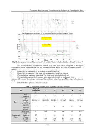
the iterative process in both workflows. As it‟s schematically shown in Fig. 1, the 3D CAD model is first
transferred from the CAD software to the idealisation module. Then, the idealisation module generates a
simplified geometry which belongs to the FEM needs. After that, the idealised CAD model is transferred to the
FEM software to create meshed and loaded structural model. Finally, the FE analysis is done and the obtained
76](https://image.slidesharecdn.com/j09067690-140201012515-phpapp02/85/International-Journal-of-Engineering-Research-and-Development-1-320.jpg)
![Towards a Ship Structural Optimisation Methodology at Early Design Stage
results for the objective function and the constraints previously defined are transferred to the optimiser tool to be
evaluated, in order to modify the design variables (plate thickness, stiffener dimensions, stiffener spacing, etc)
and to create a new structural model. The optimisation iteration process will be continued until the convergence
is attained.
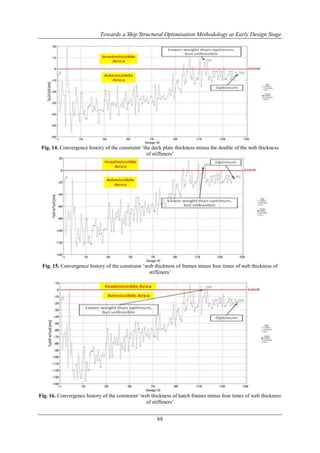
Fig. 1. Schematic of optimisation workflow
II.
MODEL FOR ANALYSIS
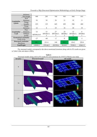
The deck structure model was quite similarly created by CAD AVEVA Marine software [5] and CAD
FORAN software [6]. The structure is constituted by deck plate, longitudinal girders, transversal frames,
longitudinal stiffeners placed between girders, and two longitudinal walls along with its stiffeners. In AVEVA
Marine model, the longitudinal stiffeners placed between girders and the stiffeners placed on two longitudinal
walls were taken into consideration as beam members (Fig. 2-a) while those in FORAN model were considered
as plate members (Fig. 2-b).
a) AVEVA Marine case study
b) FORAN case study
Fig. 2. Deck structure model
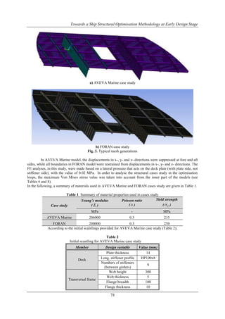
Among the elements inside the library of ANSYS [7], SHELL63 and beam44 were selected in order to
respectively discretise the plate and beam members (Fig. 3).
77](https://image.slidesharecdn.com/j09067690-140201012515-phpapp02/85/International-Journal-of-Engineering-Research-and-Development-2-320.jpg)
![Towards a Ship Structural Optimisation Methodology at Early Design Stage
Web height
600
Web thickness
5
Hatch frame
Flange breadth
100
Flange thickness
10
Web height
600
Web thickness
5
Longitudinal girder
Flange breadth
100
Flange thickness
10
Plate thickness
10
Longitudinal wall
Stiffener profile
HP160x8
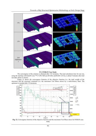
and for FORAN case study (Table 3), the total structural weights are respectively 80649.92 kg and 74904 Kg.
Table 3
Initial scantling for FORAN case study
Member
Design variable
Plate thickness
Deck
Stiffener (between girders)
Web height
Web thickness
Transversal frame
Flange breadth
Flange thickness
Web height
Hatch frame
Web thickness
Web height
Web thickness
Longitudinal girder
Flange breadth
Flange thickness
Plate thickness
Longitudinal wall
Stiffener (placed on walls)
III.
Value (mm)
14
114x8
300
5
200
10
600
5
600
5
100
10
5
180x10
OPTIMISATION WORFLOW DESCRIPTION
III.1 AVEVA Marine based Workflow
Figure 4 presents the integration development of the optimisation workflow using AVEVA Marine
12.0.SP6.39, ANSYS Classic 14.0 and modeFRONTIER 4.4.2 [8] as CAD software, FEM software and
optimiser tool respectively. The design variables used in the optimisation loop along with their lower and upper
bounds are given in Table 4.
Table 4
Design variables limits for AVEVA case study
Member
Deck
Transversal frame
Longitudinal girder
Longitudinal wall
Design variable
Min (mm)
Max (mm)
Plate thickness
Long. stiffener profile
Numbers of stiffeners
(between girders)
Web height
Web thickness
Flange breadth
Flange thickness
Web height
Web thickness
Flange breadth
Flange thickness
Plate thickness
5
HP80x6
40
HP430x20
5
15
200
5
50
5
200
5
50
5
5
1000
40
500
40
1000
40
500
40
40
Stiffener profile
HP80x6
HP430x20
79](https://image.slidesharecdn.com/j09067690-140201012515-phpapp02/85/International-Journal-of-Engineering-Research-and-Development-4-320.jpg)
![Towards a Ship Structural Optimisation Methodology at Early Design Stage
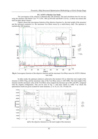
Also, the geometrical constraints imposed can be seen in Fig. 4 (see ellipse outline). Among which can
be mentioned the following [9]:
Web thickness of stiffeners to be less than the double of the deck plate thickness
The deck plate thickness to be less than the double of web thickness of stiffeners
Web height of frames to be greater than the web height of stiffeners
Fig. 4. AVEVA Marine based optimisation workflow
As it‟s shown above in red outline, AVEVA Marine is first lunched to create FEM model and to export
it to ANSYS Classic input file (APDL file). Then, the automatic loading tool shown in orange outline combines
the provided APDL file with the file included mesh generation, boundary and loading conditions, in order to be
read by ANSYS Classic. After that, the FE analysis is done and the required results are provided in the result
extraction module shown in yellow outline. In this module, the weight of the structure was defined as objective
function to be minimised. And, as a structural constraint, maximum Von Mises stress was imposed to be less
than the yield strength of the material. Finally, the obtained results for the objective function and the constraints
previously defined are transferred to the optimiser tool (shown in green outline) to be evaluated, in order to
modify the design variables (plate thickness, stiffener dimensions, stiffener spacing, etc) and to create a new
structural model.
In this regard, from the library of algorithms included in modeFRONTIER 4.2.2, the design of
experiments was taken as a constraint satisfaction problem (CSP) to find an assignment to each variable so that
all geometrical constraints are satisfied. Also, SIMPLEX algorithm (used in mono-objective optimisation) was
chosen to determine which designs need to be evaluated.
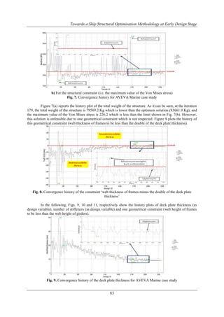
III.2 FORAN based Workflow
Figure 5 presents the integration development of the workflow using FORAN V70R1.0, ANSYS
Workbench 14.0 and modeFRONTIER 4.4.2 as CAD software, FEM software and optimiser tool respectively.
Here should be noted that the workflow provided in Fig. 5 is not a realistic optimisation, but it‟s more like a
dimensioning task. This is because the design variables used in this loop could just be taken into consideration
as below.
Deck plate thickness
Web thickness for stiffeners
80](https://image.slidesharecdn.com/j09067690-140201012515-phpapp02/85/International-Journal-of-Engineering-Research-and-Development-5-320.jpg)
![Towards a Ship Structural Optimisation Methodology at Early Design Stage
Web thickness and flange thickness for longitudinal girders
Web thickness and flange thickness for transversal frames
Wall plate thickness for longitudinal walls
The lower and upper bounds of the above-mentioned design variables were set between 5 (mm) and 40 (mm).
From the Fig. 5, by ellipse outline, the geometrical constraints imposed can be seen, among which the following
can be mentioned [9]:
Web thickness of stiffeners to be less than the double of the deck plate thickness
The deck plate thickness to be less than the double of web thickness of stiffeners
Fig. 5. FORAN based workflow
In the workflow shown above, in the red outline, the FORAN script tool reads both geometry file (STP
file) and attribute file (XML file) provided by FORAN in order to create ANSYS Workbench model (WBPJ
file). Then, in ANSYS Workbench environment, the required mesh, boundary and loading conditions are
automatically applied. After that, the FE analysis is done and the required results are provided in the result
extraction module shown in orange outline.
In this module, similar to AVEVA based optimisation workflow, the weight of the structure was
defined as objective function to be minimised. And as a structural constraint, maximum Von Mises stress was
imposed to be less than the yield strength of the material. Finally, the obtained results for the objective function
and the constraints previously defined are transferred to the optimiser tool (shown in green outline) to be
evaluated, in order to modify the design variables (i.e. thickness for the stiffeners, girders, frames and
longitudinal walls) and to create a new structural model.
In this regard, from the library of algorithms included in modeFRONTIER 4.2.2, the optimization
algorithm chosen was SIMPLEX which is used in mono-objective optimisation.
IV.
RESULTS AND DISCUSSIONS
AVEVA Marine based optimisation workflow and FORAN based workflow were successfully
validated and the obtained results are presented in this section. The communication between all integrated
software and tools are fully in an automatic process, without any manual intervention on graphical user interface.
81](https://image.slidesharecdn.com/j09067690-140201012515-phpapp02/85/International-Journal-of-Engineering-Research-and-Development-6-320.jpg)
![Towards a Ship Structural Optimisation Methodology at Early Design Stage
124
152
(optimum)
V.
CONCLUSIONS
The present work was performed in the framework of the research activity carried out by the European
Project BESST "Breakthrough in European Ship and Shipbuilding Technologies". The challenge was the
implementation of CAD and FEM software/tools in optimisation loops. Lots of efforts were put to manage
correct connections and good data exchanges between different software/modules included in innovative
structural optimisation workflows so that they successfully works in automatic processes without any manual
intervention on graphical user interfaces. In this regard, a typical ship deck structure (as an initial case study)
was taken into consideration to evaluate the iterative processes in the workflows.
The remaining study for the future is to work on a model respecting the structural necessities, in order to
improve the optimisation processes by adding more structural constraints (buckling, fatigue, vibration, etc.) and
considering additional objective functions (e.g. minimum cost, maximum inertia) to achieve a real feasible
optimum solution.
ACKNOWLEDGMENT
The present work was performed in the framework of the research activity carried out by the European
Project BESST "Breakthrough in European Ship and Shipbuilding Technologies". In this regard, the authors
wish to acknowledge the support given by European Community's Seventh Framework Programme (FP7/20072013) under grant agreement n° 233980 which has been led to the results presented in this paper.
REFERENCES
[1].
[2].
[3].
[4].
[5].
[6].
[7].
[8].
[9].
Birk L. Application of constrained multi-objective optimisation to the design of offshore structure hulls.
Journal of Offshore Mechanics and Arctic Engineering 2008; 131 (No. 1).
Doig R., Bohm M. Simulation-based structural design of ships. In: Proceedings of the 11 th International
Symposium on Practical Design of Ships and other Floating Structures (PRADS), Rio de Janeiro,
Brasil, 2010.
Bohm M. Interconnection of rules based CAD idealisation for ship structures to ANSYS. ANSYS
Conference & 28. CADFEM Users´ Meeting, Aachen, Germany, 2010.
Alonso V, Gonzalez C, Perez R. Efficient use of 3D tools at early design stages. In: Proceedings of the
12th International Conference on Computer and IT Applications in the Maritime Industries (COMPIT),
Cortona, Italy, 2013.
AVEVA Marine, Official homepage: http://www.aveva.com.
SENER Engineering Group, Official homepage of the FORAN system, Available at:
http://www.foransystem.com.
ANSYS User‟s Manual (Version 14.0). Houston, Swanson Analysis Systems Inc. 2011.
ModeFRONTIER, Official homepage: http://www.esteco.com.
LBR5 User‟s Guide (version 5.8 a). Liege, University of Liege, 2005.
90](https://image.slidesharecdn.com/j09067690-140201012515-phpapp02/85/International-Journal-of-Engineering-Research-and-Development-15-320.jpg)

The document presents an innovative workflow for ship structural optimization during the early design stage, utilizing automated processes that integrate CAD and FEM tools without manual intervention. It outlines the steps for generating simplified CAD models, conducting finite element analysis, and iteratively modifying design variables to achieve optimal weight and stress specifications. The study demonstrates successful validation of workflows, showcasing significant reductions in structural weight and stress through iterative analysis and design adjustments.