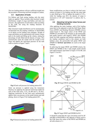
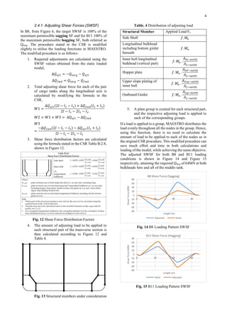
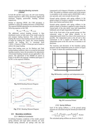
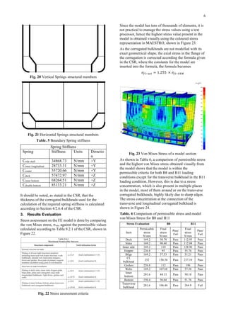
SlideShare a Scribd company logo
1 of 9
Download to read offline
Preliminary Hull Strength Assessment with MAESTRO Linear Finite Element
Modelling
By
Kang Jing ,Tay
A dissertation submitted in
Fulfilment of the partial requirements
for the degree of
Bachelor of Engineering in
Naval Architecture
School of Marine Science and Technology
Newcastle University
July 2016
Declaration
No part of the work presented in this thesis has been submitted in support of an application for another
degree or qualification of this or any other university or other institute of learning.
ABSTRACT
MAESTRO finite element program is used in an attempt
to conduct a preliminary FEM Common Structural Rules
hull strength assessment procedure for a double hull oil
tanker. MAESTRO is designed specifically for floating
structures, including ship structures. Rapid structural
modelling features takes advantage of uniformity in ship
structures. Ship based loading and loading management
features for multiple environmental and cargo loading
conditions. Comprehensive structural evaluation features
for stress and buckling assessment. A program tailored
for ship structures such as MAESTRO can potentially be
used for all stages of ship design and assessment
efficiently and effectively to achieve desired outcomes.
Utilisation of functions designed in MAESTRO in this
project has allowed substantial success in streamlining
and saving of effort and time in the CSR preliminary
assessment procedure. This project presents an example
of assessing the integrity of a working ship structure
design using the functions in MAESTRO to streamline
the lengthy and complicated preliminary procedure
recommended in the Common Structural Rules.
Keywords
FEM, Structure, IACS, Common Structural Rules,
MAESTRO
1. Introduction
The objective of classification of ships is to assess the
structural integrity of a ship. Classification has played an
integral role in the maritime industry where being in class
has become a ‘quality stamp’ for a ship’s structure,
showing that the structure is designed, constructed, and
is compliant with class rules. Today, close to all ships are
in class with a classification society.
Classification societies develops their own structural
rules and applies them to ships that are in class with them
or wants to be in class with them. A group of 12
classification societies have come together to form the
International Association of Classification Societies
(IACS). Together, these 12 classification societies cover
more than 90% of the world’s cargo tonnage.(IACS
2011) In an effort by IACS to harmonise the rules and
standards of ship classifications, the Common Structural
Rules (CSR) is produced. The CSR sets a basis for ship
assessment and is the product of the technical expertise
and experience of members of the IACS. (IACS 2016)
In assessing a ship, the classification society conducts a
range of surveys, ranging from visual to computational.
Accordance to Section 9/2.1 of the CSR for oil tankers, a
FE assessment is to be conducted to assess the structural
integrity of the hull structure. This assessment is done
accordance to the procedure laid out in the CSR and
verifies the hull structure against the required strength of
each components in the hull structure stated in the CSR.
(IACS 2010)
In this project, Finite Element program, MAESTRO, is
used to conduct the FEM assessment procedure in the
CSR to assess the integrity of a hull structure. This
project will provide some insight into utilising the
functions available in MAESTRO to streamline and
conduct the assessment procedure in the sections of
modelling, loading, constraining and stress assessment.
2. Modelling
2.1 Modelling
The design ship is a 183m Oil Product tanker. The
principal dimensions of the ship is shown in Table 1.
Table. 1 Principal Dimensions of design ship
Principal Dimensions
Length Overall (LOA) 183m
Length Between Perpendiculars (LBP) 174m
Breadth (Moulded) 32.2m
Depth (Moulded) 19.1m
Designed draft (Moulded) 11.0m
Scantling draft (Moulded) 13.0m
The model is created using MAESTRO Ship Design
program ver.11.2.0. The choice of MAESTRO is because
the program is specifically designed for floating
structures, including ship structures. The program can
potentially be used in all stages of ship design, with
functions of modelling, analysing and optimization.
MAESTRO’s modelling functions allows coarse mesh
finite element structures to be created rapidly, along with
fine meshing capabilities when needed. Analysis of
structures is by linear FEM, and this is sufficient
according to IACS Common Structural Rules for Oil
Tankers structural strength assessment procedure, which
this project will be based on. (MAESTRO) (MAESTRO
2015)
The finite element midship model created is of full
breadth and depth, and spans 3 identical cargo tanks
length, with the stools of the transverse corrugated
bulkheads at both ends modelled entirely, shown in
Figure 1.
Fig. 1 Starboard side of Full Breadth Tanker Model
The model is created with 3 or 4 nodes plate elements
and the stiffeners are created as beam elements using the
girder or stiffener functions. The mesh size follows the
longitudinal stiffening system and 3 panels between each
transverse web shown in Figure 2. To simplify the
modelling process, some structures, including stiffeners
and hopper have been adjusted slightly to match the
stiffener spacing and hence mesh sizes of other structures
as shown in Figure 3 and Figure 4.
The reduced thickness of all elements is calculated and
applied to all plating and stiffener elements according to
the formula:
𝑡 𝐹𝐸𝑀−𝑛𝑒𝑡50 = 𝑡 𝑔𝑟𝑠 − 0.5𝑡 𝑐𝑜𝑟𝑟
2
Fig. 2 Mesh size according to stiffener spacing
Fig. 3 Displaced Stiffener to simplify model
Fig. 4 Adjusted Hopper to match Girders Mesh
Corrugated bulkheads and bulkhead stools are modelled
using shell and beam elements. The shell element mesh
follows the mesh size of the inner bottom and the inner
side longitudinal, the shape of the stool and corrugation,
and the stiffeners in the stools, are adjusted to match the
meshing as shown in Figure 5.
Fig. 5 Mesh Size and Geometrical Shape of Corrugation
and stool
Most openings in the model are not required to be
modelled according to the criteria stated in the CSR,
except the openings on the transverse web in the double
bottom and the top stool, and the web ring opening.
However, none of the openings are modelled as the
openings on the transverse webs exceeds the criteria only
slightly as shown in Table 2. For the web ring openings,
due to the number of stiffeners at the area, it is not
practical to model the web ring opening using coarse
mesh finite elements. The web ring opening can be
incorporated by use of the MAESTRO/Rhino to create
the mesh and importing the geometry into the model.
Table. 2 CSR criteria for openings
Criteria
Openings do not need to
be modelled
H0/h<0.35 and g0<1.2
Openings in double
bottom web
H0/h=0.37 and g0=1.07
Openings in top stool H0/h=0.38 and g0=1.27
With completion of the model, the model is checked for
element connectivity, for free edges and for aspect ratio
of less than 3. The model is also checked for accuracy of
geometrical shape by comparing the model’s second
moment of area (Izz) and location of vertical neutral axis
(ȳ) with the original structural drawing. The small
difference in the two second moment of area and location
of vertical neutral axis shown in Table 3 may be due to
the simplifications in the modelling process, but is within
acceptable range.
Table. 3 Comparison of model and drawing geometry
2.2 Loading conditions
Standard design load combinations listed in the CSR are
to be used in the structural analysis. These load
combinations are separated into Sea-going load cases,
and Harbour and tank testing load cases, where Sea-
going load cases consists of static and dynamic loading,
and Harbour load cases only consist of static loading. In
this study, the model will only be tested in 2 of the
Harbour and Tank testing load cases, B8 and B11, shown
in Figure 6.
Fig. 6 Loading Combinations
Model Calculated
Izz (mm4
) 1.85397 x 10¹⁴
1.79 x 10¹⁴
ȳ (mm) 8.25 x 10³
8.35 x 10³
3
This two loading patterns will give sufficient insight into
the procedure of assessing structural strength of a tanker.
2.3 Application of loads
For Habour and Tank testing loading, only the static
loads are applied. These includes ship structural weight
distribution, weight of cargo and ballast, and static sea
pressure. The application of each loads is done according
to the CSR, but using the loading functions in
MAESTRO.
Ship structural weight distribution can be automatically
incorporated into the loading conditions in MAESTRO
as an option on the loading cases dialogue. Weight of
cargo and ballast can be represented with created volume
parts in the model and filling up the volume, stating the
percentage of tank filled and the density of cargo. This
automatically loads the model with the weight of the
cargo and applies the equivalent pressure on the tank
walls as shown in Figure 7 and 8.
Fig. 7 Tank wall pressure for loading pattern B8
Fig. 8 Tank wall pressure for loading pattern B11
Static sea pressure is applied using the immersion
function, by applying the relevant immersion depth for
each of the load cases, 1/3Tsc for B8 and Tsc for B11.
Applying immersion for the load cases automatically
applies static sea pressure on the model bottom and side
plating, shown in Figure 9 for loading pattern B11.
Fig. 9 Immersion pressure for loading pattern B11
Some modifications are done to achieve the load cases
criteria in Figure 6. For loading case B8, the cargo tank
is only filled up to 70% to lighten the model to 1/3Tsc,
while for loading case B11, the density of cargo is
increased to 1.35 x10⁻⁹
tonne/mm3
to achieve the Tsc
criteria.
2.4 Adjusting hull girder shear forces and
bending moments
After applying the static loadings, each of the loading
cases have to be adjusted to meet the Still Water Shear
Force (SWSF) and Bending Moment (SWBM) criteria
stated Figure 6. The target values of the SWSF and
SWBM are provided by the designer as the permissible
hull girder positive and negative SWSF and SWBM
limits for both seagoing and harbour operations. Since
the loading conditions used in this project are both
harbour cases, the permissible hull girder SWSF and
SWBM for harbour operations are used as the target
loadings.
In achieving the target SWSF and SWBM criteria, the
SWSF and SWBM of the 3 tank length model should
look approximately equivalent to Figure 10 for B8, and
Figure 11 for B11.
Fig. 10 Target SWSF and SWBM for B8
Fig. 11 Target SWSF and SWBM for B11
It should be noted that the sign convention used for SF
and BM in MAESTRO is the opposite of those used in
the CSR, hence the values of the SWSF and SWBM are
all with a factor of -1.
4
2.4.1 Adjusting Shear Forces (SWSF)
In B8, from Figure 6, the target SWSF is 100% of the
maximum permissible sagging SF and for B11 100% of
the maximum permissible hogging SF, both referred as
Qtarg. The procedure stated in the CSR is modified
slightly to utilise the loading functions in MAESTRO.
The modified procedure is as follows:
1. Required adjustments are calculated using the
SWSF values obtained from the static loaded
model,
∆𝑄 𝑎𝑓𝑡 = −𝑄𝑡𝑎𝑟𝑔 − 𝑄 𝑎𝑓𝑡
∆𝑄 𝑓𝑤𝑑 = 𝑄𝑡𝑎𝑟𝑔 − 𝑄 𝑓𝑤𝑑
2. Total adjusting shear force for each of the pair
of cargo tanks along the longitudinal axis is
calculated by modifying the formula in the
CSR,
𝑊1 =
∆𝑄 𝑎𝑓𝑡(2𝑙 − 𝑙2 − 𝑙3) + ∆𝑄 𝑓𝑤𝑑(𝑙2 + 𝑙3)
2𝑙 − 𝑙1 − 2𝑙2 − 𝑙3
𝑊2 = 𝑊1 + 𝑊3 = ∆𝑄 𝑎𝑓𝑡 − ∆𝑄 𝑓𝑤𝑑
𝑊3
=
−∆𝑄 𝑓𝑤𝑑(2𝑙 − 𝑙1 − 𝑙2) − ∆𝑄 𝑎𝑓𝑡(𝑙1 + 𝑙2)
2𝑙 − 𝑙1 − 2𝑙2 − 𝑙3
3. Shear force distribution factors are calculated
using the formula stated in the CSR Table B.2.8,
shown in Figure 12.
Fig. 12 Shear Force Distribution Factors
4. The amount of adjusting load to be applied to
each structural part of the transverse section is
then calculated according to Figure 12 and
Table 4.
Fig. 13 Structural members under consideration
Table. 4 Distribution of adjusting load
Structural Member Applied Load Fs
Side Shell 𝑓. 𝑊𝑛
Longitudinal bulkhead
including bottom girder
beneath
𝑓. 𝑊𝑛
Inner hull longitudinal
bulkhead (vertical part)
𝑓. 𝑊𝑛 .
𝐴𝑙ℎ−𝑛𝑒𝑡50
𝐴2−𝑛𝑒𝑡50
Hopper plate 𝑓. 𝑊𝑛 .
𝐴 𝐻𝑃−𝑛𝑒𝑡50
𝐴2−𝑛𝑒𝑡50
Upper slope plating of
inner hull
𝑓. 𝑊𝑛 .
𝐴 𝑈𝑠𝑝−𝑛𝑒𝑡50
𝐴2−𝑛𝑒𝑡50
Outboard Girder 𝑓. 𝑊𝑛 .
𝐴 𝑂𝑔−𝑛𝑒𝑡50
𝐴2−𝑛𝑒𝑡50
5. A plate group is created for each structural part,
and the respective adjusting load is applied to
each of the corresponding groups.
If a load is applied to a group, MAESTRO distributes the
load evenly throughout all the nodes in the group. Hence,
using this function, there is no need to calculate the
amount of load to be applied to each of the nodes as in
the original CSR procedure. This modified procedure can
save much effort and time in both calculations and
loading of the model, while achieving the same objective.
The adjusted SWSF for both B8 and B11 loading
conditions is shown in Figure 14 and Figure 15
respectively, attaining the required Qtarg of 64MN at both
bulkheads fore and aft of the middle tank.
Fig. 14 B8 Loading Pattern SWSF
Fig. 15 B11 Loading Pattern SWSF
-80
-60
-40
-20
0
20
40
60
80
0 20 40 60
ShearForce(MN)
Length (m)
B8 Shear Force (Sagging)
Adjusted Static
-80
-60
-40
-20
0
20
40
60
80
0 20 40 60
ShearForce(MN)
Length (m)
B11 Shear Force (Hogging)
Static Adjusted
5
2.4.2 Adjusting Bending moments
(SWBM)
In both B8 and B11 load cases, the still water bending
moment required is 100% of the maximum sagging and
minimum hogging permissible bending moment
respectively.
Similar to adjusting SWSF, the CSR procedure is
modified to utilise the loading functions in MAESTRO.
The required SWBM adjustments are calculated from the
following equation in the CSR:
𝑀𝑣−𝑒𝑛𝑑 = 𝑀𝑣−𝑡𝑎𝑟𝑔 − 𝑀𝑣−𝑝𝑒𝑎𝑘
The additional vertical bending moment is then
distributed evenly on both ends of the model using the
end moment loading function. This works well for
loading B8, however the bending moment still fall short
of target for loading B11, hence, the vertical bending
moment for loading B11 is increased from
5.503E+11Nmm to 7.030E+11Nmm per end of model to
achieve the target loading.
Since both loading cases are for Harbour and Tank
testing loading conditions, there is no need for horizontal
bending moments, hence the procedures for adjustments
of horizontal bending moments are not applicable to this
project. The adjustment of the SWBM are shown in
Figure 16 for B8 to the required -169MNm and Figure 17
for B11 to the required 164MNm.
Fig. 16 B8 Bending Moment Diagram
Fig. 17 B11 Bending Moment Diagram
2.5 Boundary conditions
2.5.1 Method of constrains
In defining boundary conditions of the model, ground
spring elements and rigid spline elements are used.
Ground spring elements are springs with one end
constrained in all 6 degrees of freedom, as defined in the
CSR. The global co-ordinate system used in this project
is accordance to the system used in MAESTRO, with y
axis upwards, and z axis towards the port side.
Ground spring elements with spring stiffness in the
global z degree of freedom is applied to nodes along the
deck, inner bottom and bottom shell.
Ground spring elements with spring stiffness in the
global y degree of freedom is applied to nodes along the
vertical parts of the side shells, inner hull longitudinal
bulkheads and oil-tight longitudinal bulkheads.
Each of the fixed ends of the ground springs are then
connected, using a rigid spline element, to an
independent point which is as close to the neutral axis as
possible. The independent point at the aft end is then
constrained in the x degree of freedom, with the
independent point at the fore end free to translate in all
directions.
The locations and directions of the boundary spring
elements and the independent point are shown in Figure
18. Figure 19 shows the constrained model.
Fig. 18 Boundary conditions and independent point
Fig. 19 Constrained Model
2.5.2 Spring Stiffness
Each of the spring stiffness, c, of the ground spring
elements are calculated using the formula provided in the
CSR,
𝑐 = (
𝐸
1 + 𝑣
)
𝐴 𝑠−𝑛𝑒𝑡50
𝑙 𝑡𝑘 𝑛
= 0.77
𝐴 𝑠−𝑛𝑒𝑡50 𝐸
𝑙 𝑡𝑘 𝑛
𝑁/𝑚𝑚
The calculated spring stiffness are shown in Table 5.
-200
-150
-100
-50
0
0 20 40 60
BendingMoment(MNm)
Length (m)
B8 BendingMoment
Adjusted static
-50
0
50
100
150
200
0 20 40 60
BendingMoment(MNm)
Length (m)
B11 BendingMoment
Static Adjusted
6
Fig. 20 Vertical Springs structural members
Fig. 21 Horizontal Springs structural members
Table. 5 Boundary Spring stiffness
Spring Stiffness
Spring Stiffness Units Directio
n
Cside shell 34868.73 N/mm +Y
Cinner longitudinal 28733.31 N/mm +Y
Ccenter 55720.66 N/mm +Y
Cdeck 57472.97 N/mm +Z
Cinner bottom 68264.51 N/mm +Z
Cdouble bottom 85133.21 N/mm +Z
It should be noted, as stated in the CSR, that the
thickness of the corrugated bulkheads used for the
calculation of the required spring stiffness is calculated
according to Section 4/2.6.4 of the CSR.
3. Results Evaluation
Stress assessment on the FE model is done by comparing
the von Mises stress, σvm, against the permissible values
calculated according to Table 9.2.1 of the CSR, shown in
Figure 22.
Fig. 22 Stress assessment criteria
Since the model has tens of thousands of elements, it is
not practical to manage the stress values using a text
processor, hence the highest stress value present in the
model is obtained visually using the coloured stress
representation in MAESTRO, shown in Figure 23.
As the corrugated bulkheads are not modelled with its
exact geometrical shape, the axial stress in the flange of
the corrugation is corrected according the formula given
in the CSR, where the constants for the model are
inserted into the formula, the formula becomes
𝜎𝑓𝑙−𝑎𝑐𝑡 = 1.255 × 𝜎𝑓𝑙−𝐹𝐸𝑀
Fig. 23 Von Mises Stress of a model section
As shown in Table 6, a comparison of permissible stress
and the highest von Mises stress obtained visually from
the model shows that the model is within the
permissible criteria for both B8 and B11 loading
conditions except for the transverse bulkhead in the B11
loading condition. However, this is due to a stress
concentration, which is also present in multiple places
in the model, most of them around or on the transverse
corrugated bulkheads, highly likely due to sharp edges.
The stress concentration at the connection of the
transverse and longitudinal corrugated bulkhead is
shown in Figure 24.
Table. 6 Comparison of permissible stress and model
von Mises Stress for B8 and B11
Stress Evaluation B8 B11
Item
Permissible
stress
N/mm
Final
stress
N/mm
Pass/
Fail
Final
stress
N/mm
Pass/
Fail
Deck 169.2 50.78 Pass 112.93 Pass
Sides 169.2 98.60 Pass 112.04 Pass
Inner side 169.2 110 Pass 128.96 Pass
Hopper 226.8 95 Pass 55.76 Pass
Bilge 169.2 57.53 Pass 51.21 Pass
CL
bulkhead
252 158.38 Pass 237.19 Pass
Girders 226.8 112 Pass 196 Pass
Webs 169.2 107.68 Pass 57.38 Pass
Inner
bottom
201.6 44.13 Pass 50.18 Pass
Bottom 150.4 56.64 Pass 51.76 Pass
Transverse
bulkhead
201.6 106.46 Pass 264.8 Fail
7
Fig. 24 Stress Concentration at intersection of
transverse and longitudinal corrugated bulkhead
These stress concentrations could easily be addressed
with the use of brackets to remove the edges of the
geometry. These brackets are present in the design
drawing but are not included in this coarse mesh model.
4. Conclusion
This project has successfully implemented the FEM
procedure in the CSR with MAESTRO ship design
program. Utilising the functions in MAESTRO, some of
the procedures stated in the CSR are streamlined as
shown in the relevant sections. Streamlining has not
affected the other sections of the procedure with the other
non-streamlined procedures still achieving the desired
outcome. Hence, this project has shown that MAESTRO
is not only capable of assessing a hull structure according
to the CSR, use of the MAESTRO functions in the
correct way can also save much time and effort in the
FEM assessment.
According to this preliminary assessment, this hull
structural design is proven to be viable in the portion of
stress assessment. However as mentioned in the results
evaluation section, there are some noticeable stress
concentrations due to the edges in the coarse mesh
model. This could be due to imperfections in the
modelling process or the absence of the designed
brackets which will have to be assessed with the local
fine mesh assessments. Unfortunately, MAESTRO has
limited capability of modelling complex shaped brackets
and structures in the coarse mesh model, hence the next
part of the hull structure assessment, local fine mesh
structural strength analysis, may hold more importance
than usual in the overall assessment procedure.
5. Further Work
This project has only completed the first of many steps
in the numerical assessment procedure of a hull structure.
Since MAESTRO has shown to have limited capability
in modelling complex shapes in the coarse mesh model,
leading firstly to the omission of the web ring opening
and then other structural components, incorporation of
finer meshes in the model should be explored and if
possible included into the model. The remaining steps of
the CSR assessment procedure should be conducted and
will be important in assessing the integrity of the hull
structure in other areas of failure including buckling and
fatigue failure.
Acknowledgements
Special thanks to Professor Dow for guidance, to Bing
Bing Ke for her patience in teaching me to read the ship
design drawing, and to Justin from MAESTRO support
team for his patience in answering my many questions
about MAESTRO.
Reference
IACS (2010). Common Structural Rules for Oil Tankers. http://www.iacs.org.uk/, IACS.
IACS (2011). Classification Societies - What, Why and How? www.iacs.org.uk.
IACS (2016). "IACS Common Structural Rules Homepage." Retrieved 2 May, 2016.
MAESTRO, M. "Capabilities Overview." Retrieved 26 April, 2016.
MAESTRO, M. (2015). "MAESTRO Manual."
8
Definitions of terms used in equations
Section 2.1
𝑡 𝑔𝑟𝑠 Proposed new building gross thickness excluding owner’s extras
𝑡 𝑐𝑜𝑟𝑟 Corrosion thickness addition
Section 2.4.1
ΔQaft Required adjustment in shear force at the aft bulkhead of middle tank
ΔQfwd Required adjustment in shear force at the fwd bulkhead of middle tank
Qaft Shear force due to static loads at the aft bulkhead of middle tank
Qfwd Shear force due to static loads at the fwd bulkhead of middle tank
W1 Total evenly distributed vertical load applied to the aft tank of the model
W2 Total evenly distributed vertical load applied to the middle tank of the model
W3 Total evenly distributed vertical load applied to the fore tank of the model
l Total length of model
l1 Total length of aft cargo tank
l2 Total length of middle cargo tank
l3 Total length of fore cargo tank
Fs Total load applied to individual structural member under consideration
n 1, 2, or 3
f Shear force distribution factor of structural part
Alh-net50 Plate sectional area of individual inner hull longitudinal bulkhead
AHp-net50 Plate sectional area of individual hopper plate
AUsp-net50 Plate sectional area of individual upper slope plate of inner hull
AOg-net50 Plate sectional area of individual outboard girder
A2-net50 Plate sectional area of individual inner hull longitudinal bulkhead including hopper slope plate, double bottom
side girder in way and upper slope plating
Section 2.4.2
Mv-end additional vertical bending moment to be applied at both ends of the model
Mv-targ Required Hogging or Sagging bending moment
Mv-peak Maximum or minimum Bending moment within the length of the middle tank due to static loads
Section 2.5.2
As-net50 Shearing area of the individual structural member under consideration, in mm2
, shown in Figure 20 and Figure 21
E Modulus of Elasticity, in N/mm2
v Poisson ratio of material, 0.3 for this project
ltk Length of the middle cargo tank
n number of nodal points to which the spring elements are applied to the structural member under consideration
Section 3
σfl-act Corrected Axial Stress
σfl-FEM Axial Stress obtained from FEM

More Related Content

What's hot

Critical Appraisal of Pavement Design of Ohio Department of Transportation (O...
Critical Appraisal of Pavement Design of Ohio Department of Transportation (O...Critical Appraisal of Pavement Design of Ohio Department of Transportation (O...
Critical Appraisal of Pavement Design of Ohio Department of Transportation (O...
Pranamesh Chakraborty
 
pavement analysis
pavement analysis pavement analysis
pavement analysis
Saeed Badeli
 
Chassis 2002 01-3300 design, analysis and testing of a formula sae car chassis
Chassis 2002 01-3300 design, analysis and testing of a formula sae car chassisChassis 2002 01-3300 design, analysis and testing of a formula sae car chassis
Chassis 2002 01-3300 design, analysis and testing of a formula sae car chassis
ELKINMAURICIOGONZALE
 
PT - Falling Weight Deflectometer
PT - Falling Weight DeflectometerPT - Falling Weight Deflectometer
PT - Falling Weight Deflectometer
Aditya K Pugalia
 
DESIGN OF RIGID PAVEMENT AND ITS COST-BENEFIT ANALYSIS BY USAGE OF VITRIFIED ...
DESIGN OF RIGID PAVEMENT AND ITS COST-BENEFIT ANALYSIS BY USAGE OF VITRIFIED ...DESIGN OF RIGID PAVEMENT AND ITS COST-BENEFIT ANALYSIS BY USAGE OF VITRIFIED ...
DESIGN OF RIGID PAVEMENT AND ITS COST-BENEFIT ANALYSIS BY USAGE OF VITRIFIED ...
IAEME Publication
 

What's hot (18)

Aashto08
Aashto08Aashto08
Aashto08
 
0014
00140014
0014
 
Determining equivalent single wheel load.(ESWL)
Determining equivalent single wheel load.(ESWL) Determining equivalent single wheel load.(ESWL)
Determining equivalent single wheel load.(ESWL)
 
IRJET- A Study of Cement Treated Base and Sub Base in Flexible Pavement
IRJET-  	  A Study of Cement Treated Base and Sub Base in Flexible PavementIRJET-  	  A Study of Cement Treated Base and Sub Base in Flexible Pavement
IRJET- A Study of Cement Treated Base and Sub Base in Flexible Pavement
 
Critical Appraisal of Pavement Design of Ohio Department of Transportation (O...
Critical Appraisal of Pavement Design of Ohio Department of Transportation (O...Critical Appraisal of Pavement Design of Ohio Department of Transportation (O...
Critical Appraisal of Pavement Design of Ohio Department of Transportation (O...
 
FWD_paper_IJPEfinal
FWD_paper_IJPEfinalFWD_paper_IJPEfinal
FWD_paper_IJPEfinal
 
Report on Widening and Construction of Roads
Report on Widening and Construction of RoadsReport on Widening and Construction of Roads
Report on Widening and Construction of Roads
 
Analysis of Behaviour of U-Girder Bridge Decks
Analysis of Behaviour of U-Girder Bridge DecksAnalysis of Behaviour of U-Girder Bridge Decks
Analysis of Behaviour of U-Girder Bridge Decks
 
IRJET- Seismic Analysis of Curve Cable-Stayed Bridge
IRJET- Seismic Analysis of Curve Cable-Stayed BridgeIRJET- Seismic Analysis of Curve Cable-Stayed Bridge
IRJET- Seismic Analysis of Curve Cable-Stayed Bridge
 
pavement analysis
pavement analysis pavement analysis
pavement analysis
 
Chassis 2002 01-3300 design, analysis and testing of a formula sae car chassis
Chassis 2002 01-3300 design, analysis and testing of a formula sae car chassisChassis 2002 01-3300 design, analysis and testing of a formula sae car chassis
Chassis 2002 01-3300 design, analysis and testing of a formula sae car chassis
 
IRJET- Study of Static Analysis on Conventional and Oblique Prestressed C...
IRJET-  	  Study of Static Analysis on Conventional and Oblique Prestressed C...IRJET-  	  Study of Static Analysis on Conventional and Oblique Prestressed C...
IRJET- Study of Static Analysis on Conventional and Oblique Prestressed C...
 
Interpretation Of Falling Weight Deflectometer (FWD) Data
Interpretation Of Falling Weight Deflectometer (FWD) DataInterpretation Of Falling Weight Deflectometer (FWD) Data
Interpretation Of Falling Weight Deflectometer (FWD) Data
 
Assessment of Soil Structure Interaction on RCC Underpass Bridge
Assessment of Soil Structure Interaction on RCC Underpass BridgeAssessment of Soil Structure Interaction on RCC Underpass Bridge
Assessment of Soil Structure Interaction on RCC Underpass Bridge
 
PT - Falling Weight Deflectometer
PT - Falling Weight DeflectometerPT - Falling Weight Deflectometer
PT - Falling Weight Deflectometer
 
Vd tinhtoan cautreo
Vd tinhtoan cautreoVd tinhtoan cautreo
Vd tinhtoan cautreo
 
DESIGN OF RIGID PAVEMENT AND ITS COST-BENEFIT ANALYSIS BY USAGE OF VITRIFIED ...
DESIGN OF RIGID PAVEMENT AND ITS COST-BENEFIT ANALYSIS BY USAGE OF VITRIFIED ...DESIGN OF RIGID PAVEMENT AND ITS COST-BENEFIT ANALYSIS BY USAGE OF VITRIFIED ...
DESIGN OF RIGID PAVEMENT AND ITS COST-BENEFIT ANALYSIS BY USAGE OF VITRIFIED ...
 
6 diseno optimo camino minero 2014 douglas canada
6 diseno optimo camino minero 2014 douglas canada6 diseno optimo camino minero 2014 douglas canada
6 diseno optimo camino minero 2014 douglas canada
 

Viewers also liked

Viewers also liked (15)

Resume - Anirvan
Resume - AnirvanResume - Anirvan
Resume - Anirvan
 
CV_Theo Govender
CV_Theo GovenderCV_Theo Govender
CV_Theo Govender
 
resume
resumeresume
resume
 
Santos jeanette 4.4_final_ppp_slideshow
Santos jeanette 4.4_final_ppp_slideshowSantos jeanette 4.4_final_ppp_slideshow
Santos jeanette 4.4_final_ppp_slideshow
 
Models
ModelsModels
Models
 
Fw16 r1 catalog_us-en_4_we_bv2
Fw16 r1 catalog_us-en_4_we_bv2Fw16 r1 catalog_us-en_4_we_bv2
Fw16 r1 catalog_us-en_4_we_bv2
 
Resume
ResumeResume
Resume
 
myCV13.docx
myCV13.docxmyCV13.docx
myCV13.docx
 
Marco polo
Marco poloMarco polo
Marco polo
 
Computador listo
Computador listoComputador listo
Computador listo
 
PRESENTACION DOCENTIC
PRESENTACION  DOCENTICPRESENTACION  DOCENTIC
PRESENTACION DOCENTIC
 
Toxico3
Toxico3Toxico3
Toxico3
 
Mesopotamia
MesopotamiaMesopotamia
Mesopotamia
 
Diapositivas pequi DOCENTIC
Diapositivas pequi DOCENTICDiapositivas pequi DOCENTIC
Diapositivas pequi DOCENTIC
 
Diapositivas proyecto tic
Diapositivas  proyecto ticDiapositivas  proyecto tic
Diapositivas proyecto tic
 

Similar to MAR3044 Kang Jing Tay Dissertation Report

Paper - The use of FEM for composites
Paper - The use of FEM for compositesPaper - The use of FEM for composites
Paper - The use of FEM for composites
Michael Armbruster
 
104 AAE - Introduction to CAD (submission C) (1)
104 AAE - Introduction to CAD (submission C) (1)104 AAE - Introduction to CAD (submission C) (1)
104 AAE - Introduction to CAD (submission C) (1)
Kruti Joshi AMIMechE
 
SAE BAJA Frame Structural optimization
SAE BAJA Frame Structural optimizationSAE BAJA Frame Structural optimization
SAE BAJA Frame Structural optimization
Akshay Murkute
 
Design and finite element analysis of under frame arrangement (universal head...
Design and finite element analysis of under frame arrangement (universal head...Design and finite element analysis of under frame arrangement (universal head...
Design and finite element analysis of under frame arrangement (universal head...
eSAT Journals
 

Similar to MAR3044 Kang Jing Tay Dissertation Report (20)

Airbus - Topology Optimization Methods for Optimal Aircraft Components
Airbus - Topology Optimization Methods for Optimal Aircraft ComponentsAirbus - Topology Optimization Methods for Optimal Aircraft Components
Airbus - Topology Optimization Methods for Optimal Aircraft Components
 
Lh3619271935
Lh3619271935Lh3619271935
Lh3619271935
 
Crashworthiness Design Optimization of a Conventional Skid Landing Gear Using...
Crashworthiness Design Optimization of a Conventional Skid Landing Gear Using...Crashworthiness Design Optimization of a Conventional Skid Landing Gear Using...
Crashworthiness Design Optimization of a Conventional Skid Landing Gear Using...
 
[IJET V2I5P14] Authors: Miss Kirti. S. Kakade, Prof. P. A. Narwade
[IJET V2I5P14] Authors: Miss Kirti. S. Kakade, Prof. P. A. Narwade[IJET V2I5P14] Authors: Miss Kirti. S. Kakade, Prof. P. A. Narwade
[IJET V2I5P14] Authors: Miss Kirti. S. Kakade, Prof. P. A. Narwade
 
Paper - The use of FEM for composites
Paper - The use of FEM for compositesPaper - The use of FEM for composites
Paper - The use of FEM for composites
 
STRUCTURAL ANALYSIS OF TRANSPORT FRAME
STRUCTURAL ANALYSIS OF TRANSPORT FRAMESTRUCTURAL ANALYSIS OF TRANSPORT FRAME
STRUCTURAL ANALYSIS OF TRANSPORT FRAME
 
IRJET-Multi-Material & Lightweight Design Optimization of a Volvo B9r Bus Fra...
IRJET-Multi-Material & Lightweight Design Optimization of a Volvo B9r Bus Fra...IRJET-Multi-Material & Lightweight Design Optimization of a Volvo B9r Bus Fra...
IRJET-Multi-Material & Lightweight Design Optimization of a Volvo B9r Bus Fra...
 
Crane Hook Design and Analysis
Crane Hook Design and AnalysisCrane Hook Design and Analysis
Crane Hook Design and Analysis
 
104 AAE - Introduction to CAD (submission C) (1)
104 AAE - Introduction to CAD (submission C) (1)104 AAE - Introduction to CAD (submission C) (1)
104 AAE - Introduction to CAD (submission C) (1)
 
Design of midship section based on hydrostatic and hydrodynamic loads
Design of midship section based on hydrostatic and hydrodynamic loadsDesign of midship section based on hydrostatic and hydrodynamic loads
Design of midship section based on hydrostatic and hydrodynamic loads
 
Apprioprate Boundary Condition for FEA of member isolated from global model
Apprioprate Boundary Condition for FEA of member isolated from global modelApprioprate Boundary Condition for FEA of member isolated from global model
Apprioprate Boundary Condition for FEA of member isolated from global model
 
SAE BAJA Frame Structural optimization
SAE BAJA Frame Structural optimizationSAE BAJA Frame Structural optimization
SAE BAJA Frame Structural optimization
 
Stress Analysis of a heavy duty vehicle chassis by using FEA
Stress Analysis of a heavy duty vehicle chassis by using FEAStress Analysis of a heavy duty vehicle chassis by using FEA
Stress Analysis of a heavy duty vehicle chassis by using FEA
 
IRJET- Design and Development of Hydraulic Tank through Structural and Fa...
IRJET-  	  Design and Development of Hydraulic Tank through Structural and Fa...IRJET-  	  Design and Development of Hydraulic Tank through Structural and Fa...
IRJET- Design and Development of Hydraulic Tank through Structural and Fa...
 
Stress Analysis of Automotive Chassis with Various Thicknesses
Stress Analysis of Automotive Chassis with Various ThicknessesStress Analysis of Automotive Chassis with Various Thicknesses
Stress Analysis of Automotive Chassis with Various Thicknesses
 
IRJET - Analysis of Skew Bridge using Computational Method
IRJET - Analysis of Skew Bridge using Computational MethodIRJET - Analysis of Skew Bridge using Computational Method
IRJET - Analysis of Skew Bridge using Computational Method
 
Design and finite element analysis of under frame arrangement (universal head...
Design and finite element analysis of under frame arrangement (universal head...Design and finite element analysis of under frame arrangement (universal head...
Design and finite element analysis of under frame arrangement (universal head...
 
IRJET- Analysis and Design of Berthing Structure
IRJET- Analysis and Design of Berthing StructureIRJET- Analysis and Design of Berthing Structure
IRJET- Analysis and Design of Berthing Structure
 
IRJET- Numerical Modelling of RDSO Designed Heavy Axle Load Embankment for In...
IRJET- Numerical Modelling of RDSO Designed Heavy Axle Load Embankment for In...IRJET- Numerical Modelling of RDSO Designed Heavy Axle Load Embankment for In...
IRJET- Numerical Modelling of RDSO Designed Heavy Axle Load Embankment for In...
 
Fluid-Structure Interaction Over an Aircraft Wing
Fluid-Structure Interaction Over an Aircraft WingFluid-Structure Interaction Over an Aircraft Wing
Fluid-Structure Interaction Over an Aircraft Wing
 

MAR3044 Kang Jing Tay Dissertation Report

  • 1. Preliminary Hull Strength Assessment with MAESTRO Linear Finite Element Modelling By Kang Jing ,Tay A dissertation submitted in Fulfilment of the partial requirements for the degree of Bachelor of Engineering in Naval Architecture School of Marine Science and Technology Newcastle University July 2016 Declaration No part of the work presented in this thesis has been submitted in support of an application for another degree or qualification of this or any other university or other institute of learning.
  • 2. ABSTRACT MAESTRO finite element program is used in an attempt to conduct a preliminary FEM Common Structural Rules hull strength assessment procedure for a double hull oil tanker. MAESTRO is designed specifically for floating structures, including ship structures. Rapid structural modelling features takes advantage of uniformity in ship structures. Ship based loading and loading management features for multiple environmental and cargo loading conditions. Comprehensive structural evaluation features for stress and buckling assessment. A program tailored for ship structures such as MAESTRO can potentially be used for all stages of ship design and assessment efficiently and effectively to achieve desired outcomes. Utilisation of functions designed in MAESTRO in this project has allowed substantial success in streamlining and saving of effort and time in the CSR preliminary assessment procedure. This project presents an example of assessing the integrity of a working ship structure design using the functions in MAESTRO to streamline the lengthy and complicated preliminary procedure recommended in the Common Structural Rules. Keywords FEM, Structure, IACS, Common Structural Rules, MAESTRO 1. Introduction The objective of classification of ships is to assess the structural integrity of a ship. Classification has played an integral role in the maritime industry where being in class has become a ‘quality stamp’ for a ship’s structure, showing that the structure is designed, constructed, and is compliant with class rules. Today, close to all ships are in class with a classification society. Classification societies develops their own structural rules and applies them to ships that are in class with them or wants to be in class with them. A group of 12 classification societies have come together to form the International Association of Classification Societies (IACS). Together, these 12 classification societies cover more than 90% of the world’s cargo tonnage.(IACS 2011) In an effort by IACS to harmonise the rules and standards of ship classifications, the Common Structural Rules (CSR) is produced. The CSR sets a basis for ship assessment and is the product of the technical expertise and experience of members of the IACS. (IACS 2016) In assessing a ship, the classification society conducts a range of surveys, ranging from visual to computational. Accordance to Section 9/2.1 of the CSR for oil tankers, a FE assessment is to be conducted to assess the structural integrity of the hull structure. This assessment is done accordance to the procedure laid out in the CSR and verifies the hull structure against the required strength of each components in the hull structure stated in the CSR. (IACS 2010) In this project, Finite Element program, MAESTRO, is used to conduct the FEM assessment procedure in the CSR to assess the integrity of a hull structure. This project will provide some insight into utilising the functions available in MAESTRO to streamline and conduct the assessment procedure in the sections of modelling, loading, constraining and stress assessment. 2. Modelling 2.1 Modelling The design ship is a 183m Oil Product tanker. The principal dimensions of the ship is shown in Table 1. Table. 1 Principal Dimensions of design ship Principal Dimensions Length Overall (LOA) 183m Length Between Perpendiculars (LBP) 174m Breadth (Moulded) 32.2m Depth (Moulded) 19.1m Designed draft (Moulded) 11.0m Scantling draft (Moulded) 13.0m The model is created using MAESTRO Ship Design program ver.11.2.0. The choice of MAESTRO is because the program is specifically designed for floating structures, including ship structures. The program can potentially be used in all stages of ship design, with functions of modelling, analysing and optimization. MAESTRO’s modelling functions allows coarse mesh finite element structures to be created rapidly, along with fine meshing capabilities when needed. Analysis of structures is by linear FEM, and this is sufficient according to IACS Common Structural Rules for Oil Tankers structural strength assessment procedure, which this project will be based on. (MAESTRO) (MAESTRO 2015) The finite element midship model created is of full breadth and depth, and spans 3 identical cargo tanks length, with the stools of the transverse corrugated bulkheads at both ends modelled entirely, shown in Figure 1. Fig. 1 Starboard side of Full Breadth Tanker Model The model is created with 3 or 4 nodes plate elements and the stiffeners are created as beam elements using the girder or stiffener functions. The mesh size follows the longitudinal stiffening system and 3 panels between each transverse web shown in Figure 2. To simplify the modelling process, some structures, including stiffeners and hopper have been adjusted slightly to match the stiffener spacing and hence mesh sizes of other structures as shown in Figure 3 and Figure 4. The reduced thickness of all elements is calculated and applied to all plating and stiffener elements according to the formula: 𝑡 𝐹𝐸𝑀−𝑛𝑒𝑡50 = 𝑡 𝑔𝑟𝑠 − 0.5𝑡 𝑐𝑜𝑟𝑟
  • 3. 2 Fig. 2 Mesh size according to stiffener spacing Fig. 3 Displaced Stiffener to simplify model Fig. 4 Adjusted Hopper to match Girders Mesh Corrugated bulkheads and bulkhead stools are modelled using shell and beam elements. The shell element mesh follows the mesh size of the inner bottom and the inner side longitudinal, the shape of the stool and corrugation, and the stiffeners in the stools, are adjusted to match the meshing as shown in Figure 5. Fig. 5 Mesh Size and Geometrical Shape of Corrugation and stool Most openings in the model are not required to be modelled according to the criteria stated in the CSR, except the openings on the transverse web in the double bottom and the top stool, and the web ring opening. However, none of the openings are modelled as the openings on the transverse webs exceeds the criteria only slightly as shown in Table 2. For the web ring openings, due to the number of stiffeners at the area, it is not practical to model the web ring opening using coarse mesh finite elements. The web ring opening can be incorporated by use of the MAESTRO/Rhino to create the mesh and importing the geometry into the model. Table. 2 CSR criteria for openings Criteria Openings do not need to be modelled H0/h<0.35 and g0<1.2 Openings in double bottom web H0/h=0.37 and g0=1.07 Openings in top stool H0/h=0.38 and g0=1.27 With completion of the model, the model is checked for element connectivity, for free edges and for aspect ratio of less than 3. The model is also checked for accuracy of geometrical shape by comparing the model’s second moment of area (Izz) and location of vertical neutral axis (ȳ) with the original structural drawing. The small difference in the two second moment of area and location of vertical neutral axis shown in Table 3 may be due to the simplifications in the modelling process, but is within acceptable range. Table. 3 Comparison of model and drawing geometry 2.2 Loading conditions Standard design load combinations listed in the CSR are to be used in the structural analysis. These load combinations are separated into Sea-going load cases, and Harbour and tank testing load cases, where Sea- going load cases consists of static and dynamic loading, and Harbour load cases only consist of static loading. In this study, the model will only be tested in 2 of the Harbour and Tank testing load cases, B8 and B11, shown in Figure 6. Fig. 6 Loading Combinations Model Calculated Izz (mm4 ) 1.85397 x 10¹⁴ 1.79 x 10¹⁴ ȳ (mm) 8.25 x 10³ 8.35 x 10³
  • 4. 3 This two loading patterns will give sufficient insight into the procedure of assessing structural strength of a tanker. 2.3 Application of loads For Habour and Tank testing loading, only the static loads are applied. These includes ship structural weight distribution, weight of cargo and ballast, and static sea pressure. The application of each loads is done according to the CSR, but using the loading functions in MAESTRO. Ship structural weight distribution can be automatically incorporated into the loading conditions in MAESTRO as an option on the loading cases dialogue. Weight of cargo and ballast can be represented with created volume parts in the model and filling up the volume, stating the percentage of tank filled and the density of cargo. This automatically loads the model with the weight of the cargo and applies the equivalent pressure on the tank walls as shown in Figure 7 and 8. Fig. 7 Tank wall pressure for loading pattern B8 Fig. 8 Tank wall pressure for loading pattern B11 Static sea pressure is applied using the immersion function, by applying the relevant immersion depth for each of the load cases, 1/3Tsc for B8 and Tsc for B11. Applying immersion for the load cases automatically applies static sea pressure on the model bottom and side plating, shown in Figure 9 for loading pattern B11. Fig. 9 Immersion pressure for loading pattern B11 Some modifications are done to achieve the load cases criteria in Figure 6. For loading case B8, the cargo tank is only filled up to 70% to lighten the model to 1/3Tsc, while for loading case B11, the density of cargo is increased to 1.35 x10⁻⁹ tonne/mm3 to achieve the Tsc criteria. 2.4 Adjusting hull girder shear forces and bending moments After applying the static loadings, each of the loading cases have to be adjusted to meet the Still Water Shear Force (SWSF) and Bending Moment (SWBM) criteria stated Figure 6. The target values of the SWSF and SWBM are provided by the designer as the permissible hull girder positive and negative SWSF and SWBM limits for both seagoing and harbour operations. Since the loading conditions used in this project are both harbour cases, the permissible hull girder SWSF and SWBM for harbour operations are used as the target loadings. In achieving the target SWSF and SWBM criteria, the SWSF and SWBM of the 3 tank length model should look approximately equivalent to Figure 10 for B8, and Figure 11 for B11. Fig. 10 Target SWSF and SWBM for B8 Fig. 11 Target SWSF and SWBM for B11 It should be noted that the sign convention used for SF and BM in MAESTRO is the opposite of those used in the CSR, hence the values of the SWSF and SWBM are all with a factor of -1.
  • 5. 4 2.4.1 Adjusting Shear Forces (SWSF) In B8, from Figure 6, the target SWSF is 100% of the maximum permissible sagging SF and for B11 100% of the maximum permissible hogging SF, both referred as Qtarg. The procedure stated in the CSR is modified slightly to utilise the loading functions in MAESTRO. The modified procedure is as follows: 1. Required adjustments are calculated using the SWSF values obtained from the static loaded model, ∆𝑄 𝑎𝑓𝑡 = −𝑄𝑡𝑎𝑟𝑔 − 𝑄 𝑎𝑓𝑡 ∆𝑄 𝑓𝑤𝑑 = 𝑄𝑡𝑎𝑟𝑔 − 𝑄 𝑓𝑤𝑑 2. Total adjusting shear force for each of the pair of cargo tanks along the longitudinal axis is calculated by modifying the formula in the CSR, 𝑊1 = ∆𝑄 𝑎𝑓𝑡(2𝑙 − 𝑙2 − 𝑙3) + ∆𝑄 𝑓𝑤𝑑(𝑙2 + 𝑙3) 2𝑙 − 𝑙1 − 2𝑙2 − 𝑙3 𝑊2 = 𝑊1 + 𝑊3 = ∆𝑄 𝑎𝑓𝑡 − ∆𝑄 𝑓𝑤𝑑 𝑊3 = −∆𝑄 𝑓𝑤𝑑(2𝑙 − 𝑙1 − 𝑙2) − ∆𝑄 𝑎𝑓𝑡(𝑙1 + 𝑙2) 2𝑙 − 𝑙1 − 2𝑙2 − 𝑙3 3. Shear force distribution factors are calculated using the formula stated in the CSR Table B.2.8, shown in Figure 12. Fig. 12 Shear Force Distribution Factors 4. The amount of adjusting load to be applied to each structural part of the transverse section is then calculated according to Figure 12 and Table 4. Fig. 13 Structural members under consideration Table. 4 Distribution of adjusting load Structural Member Applied Load Fs Side Shell 𝑓. 𝑊𝑛 Longitudinal bulkhead including bottom girder beneath 𝑓. 𝑊𝑛 Inner hull longitudinal bulkhead (vertical part) 𝑓. 𝑊𝑛 . 𝐴𝑙ℎ−𝑛𝑒𝑡50 𝐴2−𝑛𝑒𝑡50 Hopper plate 𝑓. 𝑊𝑛 . 𝐴 𝐻𝑃−𝑛𝑒𝑡50 𝐴2−𝑛𝑒𝑡50 Upper slope plating of inner hull 𝑓. 𝑊𝑛 . 𝐴 𝑈𝑠𝑝−𝑛𝑒𝑡50 𝐴2−𝑛𝑒𝑡50 Outboard Girder 𝑓. 𝑊𝑛 . 𝐴 𝑂𝑔−𝑛𝑒𝑡50 𝐴2−𝑛𝑒𝑡50 5. A plate group is created for each structural part, and the respective adjusting load is applied to each of the corresponding groups. If a load is applied to a group, MAESTRO distributes the load evenly throughout all the nodes in the group. Hence, using this function, there is no need to calculate the amount of load to be applied to each of the nodes as in the original CSR procedure. This modified procedure can save much effort and time in both calculations and loading of the model, while achieving the same objective. The adjusted SWSF for both B8 and B11 loading conditions is shown in Figure 14 and Figure 15 respectively, attaining the required Qtarg of 64MN at both bulkheads fore and aft of the middle tank. Fig. 14 B8 Loading Pattern SWSF Fig. 15 B11 Loading Pattern SWSF -80 -60 -40 -20 0 20 40 60 80 0 20 40 60 ShearForce(MN) Length (m) B8 Shear Force (Sagging) Adjusted Static -80 -60 -40 -20 0 20 40 60 80 0 20 40 60 ShearForce(MN) Length (m) B11 Shear Force (Hogging) Static Adjusted
  • 6. 5 2.4.2 Adjusting Bending moments (SWBM) In both B8 and B11 load cases, the still water bending moment required is 100% of the maximum sagging and minimum hogging permissible bending moment respectively. Similar to adjusting SWSF, the CSR procedure is modified to utilise the loading functions in MAESTRO. The required SWBM adjustments are calculated from the following equation in the CSR: 𝑀𝑣−𝑒𝑛𝑑 = 𝑀𝑣−𝑡𝑎𝑟𝑔 − 𝑀𝑣−𝑝𝑒𝑎𝑘 The additional vertical bending moment is then distributed evenly on both ends of the model using the end moment loading function. This works well for loading B8, however the bending moment still fall short of target for loading B11, hence, the vertical bending moment for loading B11 is increased from 5.503E+11Nmm to 7.030E+11Nmm per end of model to achieve the target loading. Since both loading cases are for Harbour and Tank testing loading conditions, there is no need for horizontal bending moments, hence the procedures for adjustments of horizontal bending moments are not applicable to this project. The adjustment of the SWBM are shown in Figure 16 for B8 to the required -169MNm and Figure 17 for B11 to the required 164MNm. Fig. 16 B8 Bending Moment Diagram Fig. 17 B11 Bending Moment Diagram 2.5 Boundary conditions 2.5.1 Method of constrains In defining boundary conditions of the model, ground spring elements and rigid spline elements are used. Ground spring elements are springs with one end constrained in all 6 degrees of freedom, as defined in the CSR. The global co-ordinate system used in this project is accordance to the system used in MAESTRO, with y axis upwards, and z axis towards the port side. Ground spring elements with spring stiffness in the global z degree of freedom is applied to nodes along the deck, inner bottom and bottom shell. Ground spring elements with spring stiffness in the global y degree of freedom is applied to nodes along the vertical parts of the side shells, inner hull longitudinal bulkheads and oil-tight longitudinal bulkheads. Each of the fixed ends of the ground springs are then connected, using a rigid spline element, to an independent point which is as close to the neutral axis as possible. The independent point at the aft end is then constrained in the x degree of freedom, with the independent point at the fore end free to translate in all directions. The locations and directions of the boundary spring elements and the independent point are shown in Figure 18. Figure 19 shows the constrained model. Fig. 18 Boundary conditions and independent point Fig. 19 Constrained Model 2.5.2 Spring Stiffness Each of the spring stiffness, c, of the ground spring elements are calculated using the formula provided in the CSR, 𝑐 = ( 𝐸 1 + 𝑣 ) 𝐴 𝑠−𝑛𝑒𝑡50 𝑙 𝑡𝑘 𝑛 = 0.77 𝐴 𝑠−𝑛𝑒𝑡50 𝐸 𝑙 𝑡𝑘 𝑛 𝑁/𝑚𝑚 The calculated spring stiffness are shown in Table 5. -200 -150 -100 -50 0 0 20 40 60 BendingMoment(MNm) Length (m) B8 BendingMoment Adjusted static -50 0 50 100 150 200 0 20 40 60 BendingMoment(MNm) Length (m) B11 BendingMoment Static Adjusted
  • 7. 6 Fig. 20 Vertical Springs structural members Fig. 21 Horizontal Springs structural members Table. 5 Boundary Spring stiffness Spring Stiffness Spring Stiffness Units Directio n Cside shell 34868.73 N/mm +Y Cinner longitudinal 28733.31 N/mm +Y Ccenter 55720.66 N/mm +Y Cdeck 57472.97 N/mm +Z Cinner bottom 68264.51 N/mm +Z Cdouble bottom 85133.21 N/mm +Z It should be noted, as stated in the CSR, that the thickness of the corrugated bulkheads used for the calculation of the required spring stiffness is calculated according to Section 4/2.6.4 of the CSR. 3. Results Evaluation Stress assessment on the FE model is done by comparing the von Mises stress, σvm, against the permissible values calculated according to Table 9.2.1 of the CSR, shown in Figure 22. Fig. 22 Stress assessment criteria Since the model has tens of thousands of elements, it is not practical to manage the stress values using a text processor, hence the highest stress value present in the model is obtained visually using the coloured stress representation in MAESTRO, shown in Figure 23. As the corrugated bulkheads are not modelled with its exact geometrical shape, the axial stress in the flange of the corrugation is corrected according the formula given in the CSR, where the constants for the model are inserted into the formula, the formula becomes 𝜎𝑓𝑙−𝑎𝑐𝑡 = 1.255 × 𝜎𝑓𝑙−𝐹𝐸𝑀 Fig. 23 Von Mises Stress of a model section As shown in Table 6, a comparison of permissible stress and the highest von Mises stress obtained visually from the model shows that the model is within the permissible criteria for both B8 and B11 loading conditions except for the transverse bulkhead in the B11 loading condition. However, this is due to a stress concentration, which is also present in multiple places in the model, most of them around or on the transverse corrugated bulkheads, highly likely due to sharp edges. The stress concentration at the connection of the transverse and longitudinal corrugated bulkhead is shown in Figure 24. Table. 6 Comparison of permissible stress and model von Mises Stress for B8 and B11 Stress Evaluation B8 B11 Item Permissible stress N/mm Final stress N/mm Pass/ Fail Final stress N/mm Pass/ Fail Deck 169.2 50.78 Pass 112.93 Pass Sides 169.2 98.60 Pass 112.04 Pass Inner side 169.2 110 Pass 128.96 Pass Hopper 226.8 95 Pass 55.76 Pass Bilge 169.2 57.53 Pass 51.21 Pass CL bulkhead 252 158.38 Pass 237.19 Pass Girders 226.8 112 Pass 196 Pass Webs 169.2 107.68 Pass 57.38 Pass Inner bottom 201.6 44.13 Pass 50.18 Pass Bottom 150.4 56.64 Pass 51.76 Pass Transverse bulkhead 201.6 106.46 Pass 264.8 Fail
  • 8. 7 Fig. 24 Stress Concentration at intersection of transverse and longitudinal corrugated bulkhead These stress concentrations could easily be addressed with the use of brackets to remove the edges of the geometry. These brackets are present in the design drawing but are not included in this coarse mesh model. 4. Conclusion This project has successfully implemented the FEM procedure in the CSR with MAESTRO ship design program. Utilising the functions in MAESTRO, some of the procedures stated in the CSR are streamlined as shown in the relevant sections. Streamlining has not affected the other sections of the procedure with the other non-streamlined procedures still achieving the desired outcome. Hence, this project has shown that MAESTRO is not only capable of assessing a hull structure according to the CSR, use of the MAESTRO functions in the correct way can also save much time and effort in the FEM assessment. According to this preliminary assessment, this hull structural design is proven to be viable in the portion of stress assessment. However as mentioned in the results evaluation section, there are some noticeable stress concentrations due to the edges in the coarse mesh model. This could be due to imperfections in the modelling process or the absence of the designed brackets which will have to be assessed with the local fine mesh assessments. Unfortunately, MAESTRO has limited capability of modelling complex shaped brackets and structures in the coarse mesh model, hence the next part of the hull structure assessment, local fine mesh structural strength analysis, may hold more importance than usual in the overall assessment procedure. 5. Further Work This project has only completed the first of many steps in the numerical assessment procedure of a hull structure. Since MAESTRO has shown to have limited capability in modelling complex shapes in the coarse mesh model, leading firstly to the omission of the web ring opening and then other structural components, incorporation of finer meshes in the model should be explored and if possible included into the model. The remaining steps of the CSR assessment procedure should be conducted and will be important in assessing the integrity of the hull structure in other areas of failure including buckling and fatigue failure. Acknowledgements Special thanks to Professor Dow for guidance, to Bing Bing Ke for her patience in teaching me to read the ship design drawing, and to Justin from MAESTRO support team for his patience in answering my many questions about MAESTRO. Reference IACS (2010). Common Structural Rules for Oil Tankers. http://www.iacs.org.uk/, IACS. IACS (2011). Classification Societies - What, Why and How? www.iacs.org.uk. IACS (2016). "IACS Common Structural Rules Homepage." Retrieved 2 May, 2016. MAESTRO, M. "Capabilities Overview." Retrieved 26 April, 2016. MAESTRO, M. (2015). "MAESTRO Manual."
  • 9. 8 Definitions of terms used in equations Section 2.1 𝑡 𝑔𝑟𝑠 Proposed new building gross thickness excluding owner’s extras 𝑡 𝑐𝑜𝑟𝑟 Corrosion thickness addition Section 2.4.1 ΔQaft Required adjustment in shear force at the aft bulkhead of middle tank ΔQfwd Required adjustment in shear force at the fwd bulkhead of middle tank Qaft Shear force due to static loads at the aft bulkhead of middle tank Qfwd Shear force due to static loads at the fwd bulkhead of middle tank W1 Total evenly distributed vertical load applied to the aft tank of the model W2 Total evenly distributed vertical load applied to the middle tank of the model W3 Total evenly distributed vertical load applied to the fore tank of the model l Total length of model l1 Total length of aft cargo tank l2 Total length of middle cargo tank l3 Total length of fore cargo tank Fs Total load applied to individual structural member under consideration n 1, 2, or 3 f Shear force distribution factor of structural part Alh-net50 Plate sectional area of individual inner hull longitudinal bulkhead AHp-net50 Plate sectional area of individual hopper plate AUsp-net50 Plate sectional area of individual upper slope plate of inner hull AOg-net50 Plate sectional area of individual outboard girder A2-net50 Plate sectional area of individual inner hull longitudinal bulkhead including hopper slope plate, double bottom side girder in way and upper slope plating Section 2.4.2 Mv-end additional vertical bending moment to be applied at both ends of the model Mv-targ Required Hogging or Sagging bending moment Mv-peak Maximum or minimum Bending moment within the length of the middle tank due to static loads Section 2.5.2 As-net50 Shearing area of the individual structural member under consideration, in mm2 , shown in Figure 20 and Figure 21 E Modulus of Elasticity, in N/mm2 v Poisson ratio of material, 0.3 for this project ltk Length of the middle cargo tank n number of nodal points to which the spring elements are applied to the structural member under consideration Section 3 σfl-act Corrected Axial Stress σfl-FEM Axial Stress obtained from FEM