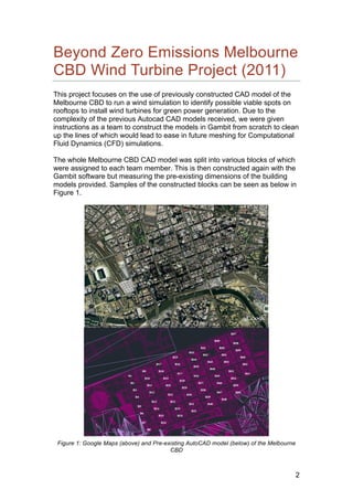
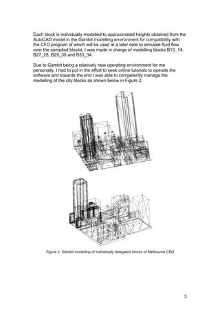
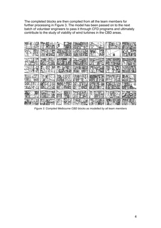
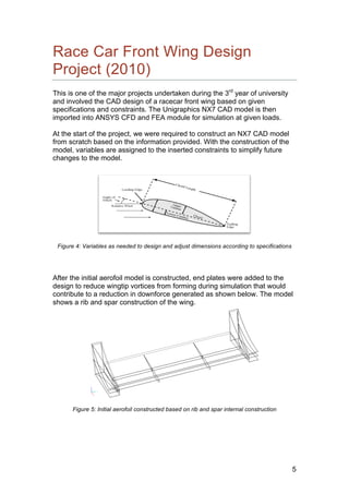
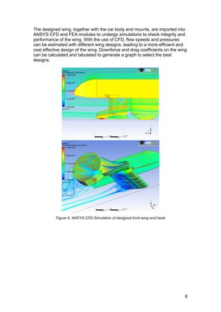
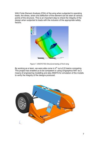
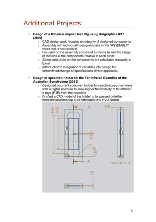
CAD Design Portfolio
KOK WEE SOON
ABSTRACT
The document will cover the two major CAD/ Simulation projects
undertaken in the final year of university of which comprises the
Beyond Zero Emissions Melbourne CBD Wind Turbine project,
Race Car Front Wing Design and Simulation competition, and also
smaller projects undertaken previously.
2
Beyond Zero Emissions Melbourne
CBD Wind Turbine Project (2011)
This project focuses on the use of previously constructed CAD model of the
Melbourne CBD to run a wind simulation to identify possible viable spots on
rooftops to install wind turbines for green power generation. Due to the
complexity of the previous Autocad CAD models received, we were given
instructions as a team to construct the models in Gambit from scratch to clean
up the lines of which would lead to ease in future meshing for Computational
Fluid Dynamics (CFD) simulations.
The whole Melbourne CBD CAD model was split into various blocks of which
were assigned to each team member. This is then constructed again with the
Gambit software but measuring the pre-existing dimensions of the building
models provided. Samples of the constructed blocks can be seen as below in
Figure 1.
Figure 1: Google Maps (above) and Pre-existing AutoCAD model (below) of the Melbourne
CBD
3
Each block is individually modelled to approximated heights obtained from the
AutoCAD model in the Gambit modelling environment for compatibility with
the CFD program of which will be used at a later date to simulate fluid flow
over the compiled blocks. I was made in charge of modelling blocks B13_14,
B27_28, B29_30 and B33_34.
Due to Gambit being a relatively new operating environment for me
personally, I had to put in the effort to seek online tutorials to operate the
software and towards the end I was able to competently manage the
modelling of the city blocks as shown below in Figure 2.
Figure 2: Gambit modelling of individually delegated blocks of Melbourne CBD
4
The completed blocks are then compiled from all the team members for
further processing in Figure 3. The model has been passed on to the next
batch of volunteer engineers to pass it through CFD programs and ultimately
contribute to the study of viability of wind turbines in the CBD areas.
Figure 3: Compiled Melbourne CBD blocks as modelled by all team members
5
Race Car Front Wing Design
Project (2010)
This is one of the major projects undertaken during the 3rd
year of university
and involved the CAD design of a racecar front wing based on given
specifications and constraints. The Unigraphics NX7 CAD model is then
imported into ANSYS CFD and FEA module for simulation at given loads.
At the start of the project, we were required to construct an NX7 CAD model
from scratch based on the information provided. With the construction of the
model, variables are assigned to the inserted constraints to simplify future
changes to the model.
Figure 4: Variables as needed to design and adjust dimensions according to specifications
After the initial aerofoil model is constructed, end plates were added to the
design to reduce wingtip vortices from forming during simulation that would
contribute to a reduction in downforce generated as shown below. The model
shows a rib and spar construction of the wing.
Figure 5: Initial aerofoil constructed based on rib and spar internal construction
6
The designed wing, together with the car body and mounts, are imported into
ANSYS CFD and FEA modules to undergo simulations to check integrity and
performance of the wing. With the use of CFD, flow speeds and pressures
can be estimated with different wing designs, leading to a more efficient and
cost effective design of the wing. Downforce and drag coefficients on the wing
can be calculated and tabulated to generate a graph to select the best
designs.
Figure 6: ANSYS CFD Simulation of designed front wing and head
7
With Finite Element Analysis (FEA) of the wing when subjected to operating
loads, the stress, strain and deflection of the element can be seen at various
points of the structure. This is an important step to check the integrity of the
design when subjected to loads with the inclusion of the appropriate safety
factors.
Figure 7: ANSYS FEA Structural testing of front wing
By working as a team, we were able come in 4th
out of 22 teams competing.
This project has enabled us to be competent in using Unigraphics NX7 as a
means of engineering modelling and also ANSYS for simulation of the models
to verify the integrity of the designs produced.
8
Additional Projects
• Design of a Materials Impact Test Rig using Unigraphics NX7
(2009)
o CAD design work focusing on integrity of designed components
o Assembly with individually designed parts in the “ASSEMBLY”
mode into a final product
o Focused on the assembly constraint functions to limit the range
of motions of the components relative to each other
o Stress and strain on the components are calculated manually in
Excel
o Introduction to integration of variables into design for
streamlined change of specifications where applicable.
• Design of specimen holder for the Far-Infrared Beamline of the
Australian Synchrotron (2011)
o Designed a current specimen holder for spectroscopy machinery
with a higher aperture to allow higher transmitivity of far-infrared
x-rays (F-IR) from the beamline
o Drafted a CAD model of the holder to be passed onto the
mechanical workshop to be fabricated and PVD coated

KW_SOON_CAD_DESIGN_PORTFOLIO

  • 1.
    CAD Design Portfolio KOKWEE SOON ABSTRACT The document will cover the two major CAD/ Simulation projects undertaken in the final year of university of which comprises the Beyond Zero Emissions Melbourne CBD Wind Turbine project, Race Car Front Wing Design and Simulation competition, and also smaller projects undertaken previously.
  • 2.
    2 Beyond Zero EmissionsMelbourne CBD Wind Turbine Project (2011) This project focuses on the use of previously constructed CAD model of the Melbourne CBD to run a wind simulation to identify possible viable spots on rooftops to install wind turbines for green power generation. Due to the complexity of the previous Autocad CAD models received, we were given instructions as a team to construct the models in Gambit from scratch to clean up the lines of which would lead to ease in future meshing for Computational Fluid Dynamics (CFD) simulations. The whole Melbourne CBD CAD model was split into various blocks of which were assigned to each team member. This is then constructed again with the Gambit software but measuring the pre-existing dimensions of the building models provided. Samples of the constructed blocks can be seen as below in Figure 1. Figure 1: Google Maps (above) and Pre-existing AutoCAD model (below) of the Melbourne CBD
  • 3.
    3 Each block isindividually modelled to approximated heights obtained from the AutoCAD model in the Gambit modelling environment for compatibility with the CFD program of which will be used at a later date to simulate fluid flow over the compiled blocks. I was made in charge of modelling blocks B13_14, B27_28, B29_30 and B33_34. Due to Gambit being a relatively new operating environment for me personally, I had to put in the effort to seek online tutorials to operate the software and towards the end I was able to competently manage the modelling of the city blocks as shown below in Figure 2. Figure 2: Gambit modelling of individually delegated blocks of Melbourne CBD
  • 4.
    4 The completed blocksare then compiled from all the team members for further processing in Figure 3. The model has been passed on to the next batch of volunteer engineers to pass it through CFD programs and ultimately contribute to the study of viability of wind turbines in the CBD areas. Figure 3: Compiled Melbourne CBD blocks as modelled by all team members
  • 5.
    5 Race Car FrontWing Design Project (2010) This is one of the major projects undertaken during the 3rd year of university and involved the CAD design of a racecar front wing based on given specifications and constraints. The Unigraphics NX7 CAD model is then imported into ANSYS CFD and FEA module for simulation at given loads. At the start of the project, we were required to construct an NX7 CAD model from scratch based on the information provided. With the construction of the model, variables are assigned to the inserted constraints to simplify future changes to the model. Figure 4: Variables as needed to design and adjust dimensions according to specifications After the initial aerofoil model is constructed, end plates were added to the design to reduce wingtip vortices from forming during simulation that would contribute to a reduction in downforce generated as shown below. The model shows a rib and spar construction of the wing. Figure 5: Initial aerofoil constructed based on rib and spar internal construction
  • 6.
    6 The designed wing,together with the car body and mounts, are imported into ANSYS CFD and FEA modules to undergo simulations to check integrity and performance of the wing. With the use of CFD, flow speeds and pressures can be estimated with different wing designs, leading to a more efficient and cost effective design of the wing. Downforce and drag coefficients on the wing can be calculated and tabulated to generate a graph to select the best designs. Figure 6: ANSYS CFD Simulation of designed front wing and head
  • 7.
    7 With Finite ElementAnalysis (FEA) of the wing when subjected to operating loads, the stress, strain and deflection of the element can be seen at various points of the structure. This is an important step to check the integrity of the design when subjected to loads with the inclusion of the appropriate safety factors. Figure 7: ANSYS FEA Structural testing of front wing By working as a team, we were able come in 4th out of 22 teams competing. This project has enabled us to be competent in using Unigraphics NX7 as a means of engineering modelling and also ANSYS for simulation of the models to verify the integrity of the designs produced.
  • 8.
    8 Additional Projects • Designof a Materials Impact Test Rig using Unigraphics NX7 (2009) o CAD design work focusing on integrity of designed components o Assembly with individually designed parts in the “ASSEMBLY” mode into a final product o Focused on the assembly constraint functions to limit the range of motions of the components relative to each other o Stress and strain on the components are calculated manually in Excel o Introduction to integration of variables into design for streamlined change of specifications where applicable. • Design of specimen holder for the Far-Infrared Beamline of the Australian Synchrotron (2011) o Designed a current specimen holder for spectroscopy machinery with a higher aperture to allow higher transmitivity of far-infrared x-rays (F-IR) from the beamline o Drafted a CAD model of the holder to be passed onto the mechanical workshop to be fabricated and PVD coated