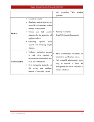
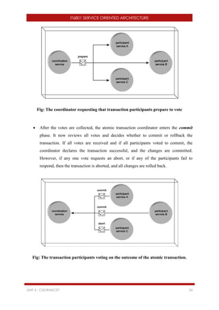
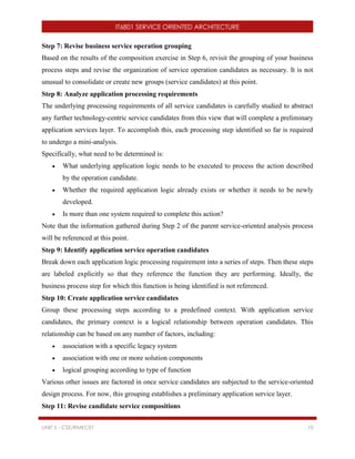
This document outlines the objectives and content of the IT6801 Service Oriented Architecture course. The course aims to teach students XML fundamentals, building XML-based applications, understanding service oriented architecture principles, web services technology elements, and building SOA-based applications. The course contains 5 units that cover topics like XML document structure, XML schemas, SOA characteristics, web service standards, and composing SOA applications. Students will learn to build applications based on XML, develop web services, and create SOA solutions for enterprise applications.


![IT6801 SERVICE ORIENTED ARCHITECTURE
UNIT 1 - CSE/RMKCET 5
Document Type Declaration
The Document Type Declaration (DOCTYPE) gives a name to the XML content and
provides a means to guarantee the document’s validity, either by including or specifying a
link to a Document Type Definition (DTD).
General Forms of the Document Type Declarations
<!DOCTYPE NAME SYSTEM “file”>
<!DOCTYPE NAME SYSTEM [ ]>
<!DOCTYPE NAME SYSTEM “file” [ ]>
In the first form listed, the DOCTYPE is referring to a document that only allows use of an
externally defined DTD subset. The second declaration only allows an internally defined
subset within the document. The final listing provides a place for inclusion of an internally
defined DTD subset between the square brackets while also making use of an external subset.
In the preceding listing, the keyword NAME should be replaced with the actual root element
contained in the document, and the “file” keyword should be replaced with a path to a valid
DTD.
Markup and Content
In general, six kinds of markup can occur in an XML document: elements, entity references,
comments, processing instructions, marked sections, and Document Type Declarations.
Elements
Within an XML document, elements are the most common form of markup. XML elements
are either a matched pair of XML tags or single XML tags that are “self-closing.” Matching
XML tags consist of markup tags that contain the same content, except that the ending tag is
prefixed with a forward slash.
<regno> Opening Tag / Start Tag
</regno> Closing Tag / End Tag
When elements do not come in pairs, the element name is suffixed by the forward slash.
These “unmatched” elements are known as empty elements.
<br/> Empty Elements](https://image.slidesharecdn.com/soait6801-171221090632/85/IT6801-Service-Oriented-Architecture-6-320.jpg)

![IT6801 SERVICE ORIENTED ARCHITECTURE
UNIT 1 - CSE/RMKCET 7
that a parser is allowed to silently discard. However, the application that receives the
information is free to ignore any processing instruction it doesn’t understand.
Processing instructions begin with <? and end with ?>. The starting <? is followed by an
XML name called the target, which identifies the program that the instruction is intended for,
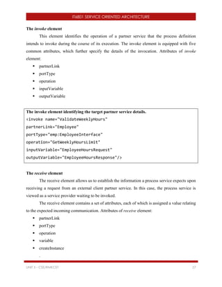
followed by data for that program. Processing instructions have the following form:
<?target data?>
Eg: <?xml-stylesheet type=”text/xsl” href=”appUsers.xslt” ?>
The target in this example is xml-stylesheet.
CDATA
CDATA stands for Character Data. CDATA sections provide a way to tell the parser that
there is no markup in the characters contained by the CDATA section. This makes it much
easier to create documents containing sections where markup characters might appear, but
where no markup is intended. Everything inside a CDATA section is ignored by the parser.
A CDATA section starts with "<![CDATA[" and ends with "]]>":
<example-code>
<![CDATA[
while (x <len&& !done) {
print( "Still working, 'zzzz'." );
++x;
}
]]>
</example-code>
Rules of XML Structure
All XML Elements Must Have a Closing Tag
XML requires all tags to be closed. They can be closed by matching a beginning element tag
with a closing tag, or they can be closed by the use of empty elements. In either case, no tag
may be left unclosed.](https://image.slidesharecdn.com/soait6801-171221090632/85/IT6801-Service-Oriented-Architecture-8-320.jpg)


![IT6801 SERVICE ORIENTED ARCHITECTURE
UNIT 1 - CSE/RMKCET 14
External DTD: DTD is declared in an external file.
The Document Type Declaration
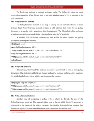
A document type declaration begins with <!DOCTYPE and ends with a >. In between is the
name of the root element, followed either by a pair of square brackets containing the DTD itself
or by the SYSTEM keyword and a URL where the DTD can be found (or, occasionally, both). A
document type declaration has this basic form:
<!DOCTYPE rootelement SYSTEM | PUBLIC DTDlocation [
internalDTDelements ] >
The exclamation mark (!) is used to signify the beginning of the declaration.
DOCTYPE is the keyword used to denote this as a Document Type Definition.
rootelement is the name of the root element or document element of the XML document.
SYSTEM and PUBLIC are keywords used to designate that the DTD is contained in an
external document. Although the use of these keywords is optional, to reference an
external DTD you would have to use one or the other. The SYSTEM keyword is used in
tandem with a URL to locate the DTD. The PUBLIC keyword specifies some public
location that will usually be some application-specific resource reference.
internalDTDelements are internal DTD declarations. These declarations will always be
placed within opening ([) and closing (]) brackets.
DTD Elements
Each element in the DTD should be defined with the following syntax:
<!ELEMENT elementname rule >
o ELEMENT is the tag name that specifies that this is an element definition.
o elementname is the name of the element.
o rule is the definition to which the element’s data content must conform.
Elements are declared using element declarations. Each element declaration gives the
name of the element and lists the elements and text that it can contain. This list is called
the content specification. For example, this element declaration for the firstName element
says that elements with the name firstName must contain only parsed character data:
<!ELEMENT firstName (#PCDATA)>](https://image.slidesharecdn.com/soait6801-171221090632/85/IT6801-Service-Oriented-Architecture-15-320.jpg)


![IT6801 SERVICE ORIENTED ARCHITECTURE
UNIT 1 - CSE/RMKCET 19
inserted in the XML document. This is much better than having to retype the same information
over and over.
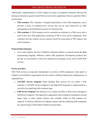
The general syntax of an entity is as follows:
<!ENTITY entityname [SYSTEM | PUBLIC] entitycontent>
ENTITY is the tag name that specifies that this definition will be for an entity.
entityname is the name by which the entity will be referred in the XML document.
entitycontent is the actual contents of the entity—the data for which the entity is serving
as a placeholder.
SYSTEM and PUBLIC are optional keywords. Either one can be added to the definition of
an entity to indicate that the entity refers to external content.
Internal Entity
DTD
<!ENTITY cpy “Copyright RMKCET 2017”>
Usage:
<copyright>&cpy;</copyright>
When the XML document containing the above content is parsed, &cpy; will be replaced with
“Copyright RMKCET 2017” in each instance in which it is used. Using the entity &cpy; saves
the XML document author from having to type in “Copyright RMKCET 2017” over and over.
External Entities
External entities are used to reference external content.
DTD
<!ENTITY rahul SYSTEM “http://srvr/emps/rahul.xml”>
Usage:
<staff>&rahul;</staff>
Non-Text External Entities and Notations
Some external entities will contain non-text data, such as an image file. We do not want the
XML parser to attempt to parse these types of files. The NDATA keyword is used to alert the
parser that the entity content should be sent unparsed to the output document.](https://image.slidesharecdn.com/soait6801-171221090632/85/IT6801-Service-Oriented-Architecture-20-320.jpg)


![IT6801 SERVICE ORIENTED ARCHITECTURE
UNIT 1 - CSE/RMKCET 26
XFiles: XPath, XPointer and XLink
XPath
XPath is a syntax for specifying a collection of elements or other information contained within
an XML document.
Conceptually, XPath assumes that the XML document to which XPath expressions will be
applied has been parsed into an internal tree representation. The XPath tree model is similar to
the DOM tree. For example, the nodes in an XPath tree are of different types, such as element,
text, and comment nodes. In addition, unlike the DOM model, the XPath tree model also uses
nodes to represent attribute name value pairs.
The root of the XPath parse tree is known as the document root. Like an instance of Document in
the DOM, this node of the XPath parse tree has a child node representing the root of the element
hierarchy in the parsed document; this node is called the document element.
Location Path
An XPath expression that represents one or more nodes within an XPath parse tree is known as a
location path. A location path can be absolute or relative.
An absolute location path starts with a slash ( / ) and a relative location path does not. In both
cases the location path consists of one or more location steps, each separated by a slash:
An absolute location path:
/step/step/...
A relative location path:
step/step/...
Each step is evaluated against the nodes in the current node-set.A step consists of:
an axis (defines the tree-relationship between the selected nodes and the current node)
a node-test (identifies a node within an axis)
zero or more predicates (to further refine the selected node-set)
The syntax for a location step is:
axisname::nodetest[predicate]](https://image.slidesharecdn.com/soait6801-171221090632/85/IT6801-Service-Oriented-Architecture-27-320.jpg)


![IT6801 SERVICE ORIENTED ARCHITECTURE
UNIT 1 - CSE/RMKCET 29
<book category="WEB">
<title lang="en">Learning XML</title>
<author>Erik T. Ray</author>
<year>2003</year>
<price>39.95</price>
</book>
</bookstore>
Program: books.xml
Example XPath Expressions
/bookstore/book/title - selects all the title nodes
/bookstore/book[1]/title - selects the title of the first book node under the
bookstore element
/bookstore/book/price[text()] - selects the text from all the price nodes
/bookstore/book[price>35]/price - selects all the price nodes with a price higher than 35
/bookstore/book[price>35]/title - selects all the title nodes with a price higher than 35
XPointer
The XML Pointer Language (XPointer) builds on the XPath specification. An XPointer uses
location steps the same as XPath but with two major differences: Because an XPointer describes
a location within an external document, an XPointer can target a point within that XML
document or a range within the target XML document.
Because XPointer builds on the XPath specification, the location steps within an XPointer are
comprised of the same elements that make up XPath location steps.
In addition to the node tests already listed for XPath expressions, XPointer provides two more
important node tests:
point()
range()
For this new functionality to work correctly, the XPointer specification added the concept of a
location within an XML document. Within XPointer, a location can be an XPath node, a point, or](https://image.slidesharecdn.com/soait6801-171221090632/85/IT6801-Service-Oriented-Architecture-30-320.jpg)

![IT6801 SERVICE ORIENTED ARCHITECTURE
UNIT 1 - CSE/RMKCET 31
<City>Houston</City>
<State>TX</State>
<Zip>77301</Zip>
</Address>
</Person>
</People>
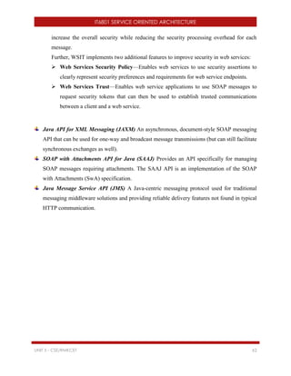
XPointer Expression Location
/People/Person[1]/Name/text()/point()[position()=4] Just after the l and just before the start o
in Dillon
/People/Person[1]/Name/text()/start-
point()[position()=0]
Just before the D in Dillon
/People/Person[2]/Address/ start-point()[position()=2] Just before the <State> element in the
<Person> element for Madi Larsen
/People/Person[2]/Address/ start-point()[position()=0] Just before the <Street> element in
the <Person> element for Madi Larsen
XLink
The XML Linking Language, XLink, allows a link to another document to be specified on any
element within an XML document. The XML Linking Language creates a link to another
resource through the use of attributes specified on elements, not through the actual elements
themselves.
Attribute Description
xlink:type This attribute must be specified and indicates what type of XLink is represented
or defined.
xlink:href This attribute contains the information necessary to locate the desired resource.
xlink:role This attribute describes the function of the link between the current resource and
another.
xlink:arcrole This attributes describes the function of the link between the current resource and](https://image.slidesharecdn.com/soait6801-171221090632/85/IT6801-Service-Oriented-Architecture-32-320.jpg)


![IT6801 SERVICE ORIENTED ARCHITECTURE
UNIT 2 - CSE/RMKCET 6
public DOMDemo() throws Exception {
DocumentBuilderFactory documentBuilderFactory =
DocumentBuilderFactory.newInstance();
documentBuilder =
documentBuilderFactory.newDocumentBuilder();
}
public static void main(String[] args) throws Exception {
String fileName = "employee.xml";
DOMDemo dom = new DOMDemo();
dom.parse(fileName);
dom.printAllElements();
}
public void parse(String fileName) throws Exception {
File inputFile = new File(fileName);
Document doc = documentBuilder.parse(inputFile);
root = doc.getDocumentElement();
System.out.println("Root element is:" + root.getNodeName());
}
public void printAllElements() throws Exception {
printElement("", root);
}
public void printElement(String indent, Node aNode) {
if (aNode.getNodeType() == Node.TEXT_NODE) {
System.out.println(indent + aNode.getNodeValue());
} else {](https://image.slidesharecdn.com/soait6801-171221090632/85/IT6801-Service-Oriented-Architecture-39-320.jpg)

![IT6801 SERVICE ORIENTED ARCHITECTURE
UNIT 2 - CSE/RMKCET 8
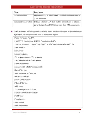
Creating an XML Document
package xml;
import java.io.File;
import javax.xml.parsers.*;
import javax.xml.transform.*;
import javax.xml.transform.dom.DOMSource;
import javax.xml.transform.stream.StreamResult;
import org.w3c.dom.*;
public class DOMCreationDemo {
public static final String xmlFilePath = "company.xml";
public static void main(String argv[]) {
try {](https://image.slidesharecdn.com/soait6801-171221090632/85/IT6801-Service-Oriented-Architecture-41-320.jpg)


![IT6801 SERVICE ORIENTED ARCHITECTURE
UNIT 2 - CSE/RMKCET 14
for (int i = 0; i < n; i += 1) {
System.out.print("" + attributes.getQName(i) + "='" +
attributes.getValue(i) + "");
}
System.out.println(">");
}
public void characters(char[] ch, int start, int length) {
System.out.println(new String(ch, start, length).trim());
}
public void endElement(String namespaceURI, String localName,
String qName) throws SAXException {
System.out.println("</" + qName + ">");
}
public static void main(String args[]) throws Exception {
String fileName = "employee.xml";
SAXDemo handler = new SAXDemo();
SAXParserFactory factory = SAXParserFactory.newInstance();
SAXParser parser = factory.newSAXParser();
parser.parse(new File(fileName), handler);
}
}](https://image.slidesharecdn.com/soait6801-171221090632/85/IT6801-Service-Oriented-Architecture-47-320.jpg)


![IT6801 SERVICE ORIENTED ARCHITECTURE
UNIT 2 - CSE/RMKCET 18
public void warning(SAXParseException e) {
valid = false;
}
public boolean isValid() {
return valid;
}
public boolean isWellFormed() {
return wellFormed;
}
public static void main(String args[]) throws Exception {
XMLReader parser = XMLReaderFactory.createXMLReader();
SAXValidationDemo handler = new SAXValidationDemo();
parser.setContentHandler(handler);
parser.setErrorHandler(handler);
parser.parse(new InputSource(new
FileReader("employee.xml")));
if (!handler.isWellFormed()) {
System.out.println("Document is NOT well formed.");
}
if (!handler.isValid()) {
System.out.println("Document is NOT valid.");
}
if (handler.isWellFormed() && handler.isValid()) {
System.out.println("Document is well formed and
valid.");
}
}
}](https://image.slidesharecdn.com/soait6801-171221090632/85/IT6801-Service-Oriented-Architecture-51-320.jpg)


![IT6801 SERVICE ORIENTED ARCHITECTURE
UNIT 2 - CSE/RMKCET 23
return phone;
}
@XmlElement(name = "phone")
public void setPhone(String phone) {
this.phone = phone;
}
@Override
public String toString() {
return "Address [name=" + name + ", company=" + company + ",
phone=" + phone + "]";
}
}
/*Unmarshaling – XML to Java*/
package xml;
import java.io.File;
import javax.xml.bind.JAXBContext;
import javax.xml.bind.JAXBException;
import javax.xml.bind.Unmarshaller;
public class JAXBUnmarshalDemo {
public static void main(String[] args) {
try {](https://image.slidesharecdn.com/soait6801-171221090632/85/IT6801-Service-Oriented-Architecture-56-320.jpg)
![IT6801 SERVICE ORIENTED ARCHITECTURE
UNIT 2 - CSE/RMKCET 24
File file = new File("address.xml");
JAXBContext jaxbContext = JAXBContext.newInstance(Address.class);
Unmarshaller jaxbUnmarshaller = jaxbContext.createUnmarshaller();
Address address = (Address) jaxbUnmarshaller.unmarshal(file);
System.out.println(address);
} catch (JAXBException e) {
e.printStackTrace();
}
}
}
Output
Address [name=Ajeeth, company=Google, phone=(011) 123-4567]
/*Marshaling – Java Objects to XML*/
package xml;
import java.io.File;
import javax.xml.bind.JAXBContext;
import javax.xml.bind.JAXBException;
import javax.xml.bind.Marshaller;
public class JAXBMarshalDemo {
public static void main(String[] args) {
Address address = new Address();
address.setName("Rahul Dravid");
address.setCompany("Rajasthan Royals");
address.setPhone("99999 88888");
try {
File file = new File("address.xml");](https://image.slidesharecdn.com/soait6801-171221090632/85/IT6801-Service-Oriented-Architecture-57-320.jpg)


![IT6801 Service Oriented Architecture
Unit 1 - Prepared by CSE Department, RMKCET Page 4
XPointer is an extension to XPath. It is also used to locate elements or data in the
XML document.
16. Define XLink.
XLink is a W3C specification which describes methods for allowing elements to be
inserted into XML documents in order to create and describe links between resources,
whether internal or external to the original document.
17. List some XSD Indicators.
Content models (Order)
o xs:sequence, xs:all, xs:choice
Group Indicators
o xs:group, xs:attributeGroup
Occurrence Indicators
o minOccurs, maxOccurs
18. List some XLink attributes.
xlink:role, xlink:href, xlink:type, xlink:from, xlink:to
19. Define location path.
An XPath expression that represents one or more nodes within an XPath parse tree is
known as a location path. A location path can be absolute or relative. The location
path consists of one or more location steps, each separated by a slash.
The syntax for a location step is: axisname::nodetest[predicate]
Example: /bookstore/book/title
20. Define the terms Axis, node test and predicate.
Axis: It specifies the tree relationship between the nodes selected by the location
step and the context node.
Node Test: It specifies the node type and expanded-name of the nodes selected by
the location step.
Predicate: It uses arbitrary expressions to further refine the set of nodes selected
by the location step.](https://image.slidesharecdn.com/soait6801-171221090632/85/IT6801-Service-Oriented-Architecture-213-320.jpg)