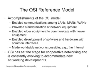
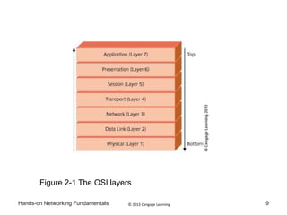
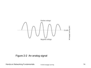
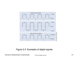
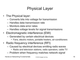
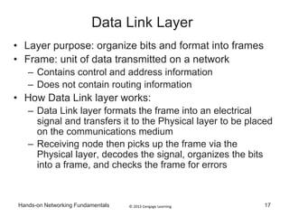
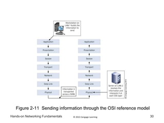
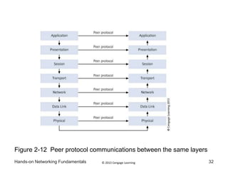
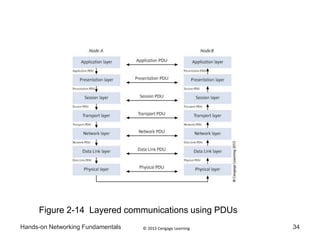
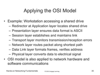
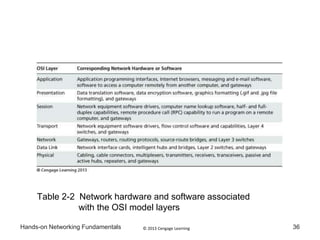
Hands-on Networking
Fundamentals,
2nd ed.
Chapter 2: How LAN and WAN
Communications Work
© 2013 Cengage LearningHands-on Networking Fundamentals 2
Objectives
• Explain the OSI reference model, which sets
standards for LAN and WAN communications
• Discuss communication between OSI stacks when
two computers are linked through a network
• Apply the OSI model to realistic networking situations
• Describe major LAN transmission methods
© 2013 Cengage LearningHands-on Networking Fundamentals 3
Objectives (continued)
• Explain the basic WAN network communications
topologies and transmission methods, including
telecommunications, cable TV, satellite and
wireless technologies
• Explain the advantages of using Ethernet in network
designs
© 2013 Cengage LearningHands-on Networking Fundamentals 4
The OSI Reference Model
• Networks work because standards have been
implemented to ensure devices from different vendors
will work together
• Open Systems Interconnection (OSI) reference model
– Fundamental network communications model
• Understanding the OSI model enable you to:
– Choose the best equipment for the job
– Create the most effective network designs
– Design networks that will communicate with other
networks
– Troubleshoot network problems more effectively
© 2013 Cengage LearningHands-on Networking Fundamentals
The OSI Reference Model
• OSI model product of two standards organizations
– International Organization for Standardization (ISO)
– American National Standards Institute (ANSI)
• The OSI model was developed in the 1970s
• Represents an effort to standardize network
software and hardware implementation
5
© 2013 Cengage LearningHands-on Networking Fundamentals 6
The OSI Reference Model
• Accomplishments of the OSI model
– Enabled communications among LANs, MANs, WANs
– Provided standardization of network equipment
– Enabled older equipment to communicate with newer
equipment
– Enabled development of software and hardware with
common interfaces
– Made worldwide networks possible; e.g., the Internet
• OSI has set the stage for cooperative networking and
is constantly evolving to accommodate new
networking developments
© 2013 Cengage LearningHands-on Networking Fundamentals
The OSI Reference Model
• The OSI model is a theoretical model and not a
specific hardware device or software routine
• It is a set of guidelines for vendors to consider and
follow when they design communications hardware
of software
• OSI guidelines specify:
– How network devices contact each other and how
devices using different protocols communicate
– How a network device knows when to transmit or not
transmit data
7
© 2013 Cengage LearningHands-on Networking Fundamentals
The OSI Reference Model
• OSI guidelines specify (continued):
– How the physical network devices are arranged and
connected
– Methods to ensure that network transmissions are
received correctly
– How network devices maintain a consistent rate of data
flow
– How electronic data is represented on the network media
• There are 7 layers in the OSI Model: Physical, Data
Link, Network, Transport, Session, Presentation, and
Application
8
© 2013 Cengage LearningHands-on Networking Fundamentals 9
Figure 2-1 The OSI layers
© 2013 Cengage LearningHands-on Networking Fundamentals 10
The OSI Reference Model
• Set of layers in OSI model is called a stack
• Communications between two network devices go up and
down the layered stack at each device
• Contact between a workstation and server
– Communications begin at the Application layer of the
workstation
– Specific information is formatted at each layer of the stack
until reaching the Physical layer where it is sent out to the
communication medium
– The server picks up the data at the Physical layer and sends
it up each layer for interpretation until reaching the
Application layer
© 2013 Cengage LearningHands-on Networking Fundamentals
The OSI Reference Model
• Each layer is called by its actual name or by its
placement in the stack
– Example: Layer 1 or Physical Layer
• Bottom layers perform functions like constructing
frames and transmitting packets/frames/signals
• Middle layers coordinate network communication
between nodes, ensuring sessions without
interruptions or errors
• Top layers perform work that directly affects
software applications and data presentation
11
© 2013 Cengage LearningHands-on Networking Fundamentals 12
Physical Layer
• Layer purpose: transmit and receive signals with data
• Responsibilities of the Physical layer (Layer 1)
– All data transfer mediums
• wire cable, fiber optics, radio waves, and microwaves
– Network connectors
– The network topology
– Signaling and encoding methods
– Data transmission devices
– Network interfaces
– Detection of signaling errors
© 2013 Cengage LearningHands-on Networking Fundamentals 13
Physical Layer
• Network signals are either analog or digital
• Analog signal
– Wave pattern with positive and negative voltages
– Examples: ordinary telephone or radio signal
– Used in WANs that employ analog modems
• Digital signal generates binary 1s or 0s
– Most common signaling method on LANs and high-
speed WANs
– Example 1: +5 volts produces 1, 0 volts produce 0
– Example 2: +5 volts produces 1, -5 volts produce 0
– Example 3 (Fiber-optics): presence of light is 1, else 0
© 2013 Cengage LearningHands-on Networking Fundamentals 14
Figure 2-2 An analog signal
© 2013 Cengage LearningHands-on Networking Fundamentals 15
Figure 2-3 Examples of digital signals
© 2013 Cengage LearningHands-on Networking Fundamentals 16
Physical Layer
• The Physical layer:
– Converts bits into voltage for transmission
– Handles data transmission rate
– Monitors data error rates
– Handles voltage levels for signal transmissions
• Electromagnetic interference (EMI)
– Generated by certain electrical devices
• Fans, electric motors, portable heaters, air-conditioners
• Radio frequency interference (RFI)
– Caused by electrical devices emitting radio waves
• Radio and television stations, radio operators, cable TV
– Problem when frequency matches network signal
© 2013 Cengage LearningHands-on Networking Fundamentals 17
Data Link Layer
• Layer purpose: organize bits and format into frames
• Frame: unit of data transmitted on a network
– Contains control and address information
– Does not contain routing information
• How Data Link layer works:
– Data Link layer formats the frame into an electrical
signal and transfers it to the Physical layer to be placed
on the communications medium
– Receiving node then picks up the frame via the
Physical layer, decodes the signal, organizes the bits
into a frame, and checks the frame for errors
© 2013 Cengage LearningHands-on Networking Fundamentals
Data Link Layer
• Data Link layer checks incoming signals for
duplicate, incorrect, or partial data
• If an error is detected, it requests a retransmission
of the data
• Error detection is handled by cyclic redundancy
check (CRC)
– Calculates size of information fields in frame
– Data Link layer at sender inserts value at end of
frame
– Receiving Data Link layer checks value in frame
18
© 2013 Cengage LearningHands-on Networking Fundamentals 19
Data Link Layer
• Data Link layer contains two important sublayers
• Logical link control sublayer (LLC)
– Initiates communication link between two nodes
– Guards against interruptions to link
– Link to Network layer may be connection-oriented
• Media access control sublayer (MAC)
– Examines physical (device or MAC) address in frame
– Frame discarded if address does not match workstation
– Regulates communication sharing
• MAC address burned into chip on network interface
– Coded as a hexadecimal number; e.g., 0004AC8428DE
• First half refers to vendor, second half unique to device
© 2013 Cengage LearningHands-on Networking Fundamentals
Data Link Layer
• Two types of services are used for communication
between the LLC sublayer and the Network layer
– Type 1 – a connectionless service (does not establish a
logical connection between nodes)
• Frames are not checked to ensure that they are in the
proper sequence, there is no acknowledgment, and there
is no error recovery
– Type 2 – a connection-oriented service (a logical
connection is made before full data transfer begins)
• Each frame contains a sequence # to ensure they are
processed in the proper order, sending node does not
transmit data faster than can be received, and if errors are
detected the data is retransmitted
20
© 2013 Cengage LearningHands-on Networking Fundamentals 21
Network Layer
• Layer purpose: controls passage of packets along
routes on the network
– Physical routes: cable and wireless paths
– Logical routes: software paths
• Packet: unit of information (like a frame)
– Formatted for transmission as signal over network
– Composed of data bits in fields of information
– Corresponds to network information sent at Network
layer of OSI model
• Specific tasks of Network layer
– Optimize physical and logical routes
– Permit routers to move packets between networks
© 2013 Cengage LearningHands-on Networking Fundamentals 22
Network Layer
• Discovery: process of information gathering to
determine the best path to a destination network
• Virtual circuits: logical communication paths
– Send and receive data
– Known only to Network layers between sending and
receiving nodes
– Benefit: manage parallel data paths
• Extra duties using virtual circuits
– Checks (and corrects) packet sequence
– Addresses packets
– Resizes packets to match receiving network protocol
– Synchronizes flow of data between Network layers
© 2013 Cengage LearningHands-on Networking Fundamentals 23
Transport Layer
• Layer purpose: reliable data transmission
– Ensures data sent and received in same order
– Receiving node sends acknowledgement ("ack")
• Transport layer is responsible for tracking virtual
circuits
– Tracks unique identification value assigned to circuit
• Value is called a port or socket
• Port or socket is assigned by Session layer
– Establishes level of packet error checking
• There are 5 reliability measures used by Transport
layer protocols (Class 0 – Class 4)
• Fragments messages into smaller units
© 2013 Cengage LearningHands-on Networking Fundamentals 24
Session Layer
• Multiple goals
– Establish and maintain the link between two nodes
– Provide for orderly communication between nodes
• Establishes which node transmits first
– Determine how long node can transmit
– Determine how to recover from transmission errors
– Link each unique address to a node (like a zip code)
– Disconnects link after communication session is
finished
© 2013 Cengage LearningHands-on Networking Fundamentals 25
Session Layer
• Two-way alternate mode (TWA) for dialog control
– Sets up node to separately send and receive
– Analogize to use of walkie-talkies
– Used in half-duplex communications
• Two-way simultaneous (TWS) for dialog control
– Devices configured to send and receive at same time
– Increases efficiency two-fold
– Made possible by buffering at network interface
– Used in full-duplex communications
© 2013 Cengage LearningHands-on Networking Fundamentals 26
Presentation Layer
• Primary purpose: manages data formatting
– Acts like a syntax checker
– Ensures data is readable to receiving Presentation layer
• Translates between distinct character codes
– EBCDIC (Extended Binary Coded Decimal Interchange
Code)
• 8-bit coding method for 256-character set
• Used mainly by IBM computers
– ASCII (American Standard Code for Information
Interchange)
• 8-bit character coding method for 128 characters
• Used by workstations running Windows 7, UNIX/Linux, or Mac
OS X
© 2013 Cengage LearningHands-on Networking Fundamentals 27
Presentation Layer
• Two additional responsibilities
– Data encryption: scrambling data so that it cannot be
read if intercepted by unauthorized users
• Example 1: account password encrypted on LAN
• Example 2: credit card encrypted on a LAN
• Encryption tool: Secure Sockets Layer (SSL)
– Data compression: compact data to conserve space
• Presentation layer at receiving node decompresses data
© 2013 Cengage LearningHands-on Networking Fundamentals 28
Application Layer
• Layer purpose: Govern the user’s most direct access to
applications and network services
• Services managed by Application layer
– File transfer, file management, remote access to files and
printers, message handling for electronic mail, and
terminal emulation
• Connecting workstations to network services
– Link application into electronic mail
– Providing database access over the network
• Microsoft Windows redirector works through this layer
– Makes computer visible to another for network access
– Example: access shared folder using redirector
© 2013 Cengage LearningHands-on Networking Fundamentals 29
Communicating Between Stacks
• OSI model enables two computers to communicate
• OSI model provides standards for:
– Communicating on a LAN
– Communicating between LANs
– Internetworking between WANs and LANs (and WANs)
• Constructing a message at the sending node
– Message created at Application layer
– Message travels down stack to Physical layer
– Information at each layer is added to message
• Layer information is encapsulated
– Message sent out to the network on the Physical layer
© 2013 Cengage LearningHands-on Networking Fundamentals 30
Figure 2-11 Sending information through the OSI reference model
© 2013 Cengage LearningHands-on Networking Fundamentals 31
Communicating Between Stacks
• Interpreting the message at the receiving node
– Message travels up stack from Physical layer
– Data Link layer checks address of frame
– Data Link layer uses CRC to check frame integrity
– Network layer receives valid frame and sends up stack
• Peer protocols: enable the sending layer to
communicate with the receiving layer
• Information transferred using primitive commands
– Protocol data unit (PDU) – as information goes from one
layer to the next, new control information is added to the
PDU
© 2013 Cengage LearningHands-on Networking Fundamentals 32
Figure 2-12 Peer protocol communications between the same layers
© 2013 Cengage LearningHands-on Networking Fundamentals 33
Communicating Between Stacks
• Control data added to PDU as it traverses stack
– Next layer gets transfer instructions from previous layer
• Next layer strips transfer/control information
• Service data unit (SDU) remains after data stripped
– Peer protocols used to communicate with companion
layer
• Key points
– Each layer forms a PDU (from an SDU)
– Each PDU is communicated to counterpart PDU
© 2013 Cengage LearningHands-on Networking Fundamentals 34
Figure 2-14 Layered communications using PDUs
© 2013 Cengage LearningHands-on Networking Fundamentals 35
Applying the OSI Model
• Example: Workstation accessing a shared drive
– Redirector at Application layer locates shared drive
– Presentation layer ensures data format is ASCII
– Session layer establishes and maintains link
– Transport layer monitors transmission/reception errors
– Network layer routes packet along shortest path
– Data Link layer formats frames, verifies address
– Physical layer converts data to electrical signal
• OSI model is also applied to network hardware and
software communications
© 2013 Cengage LearningHands-on Networking Fundamentals 36
Table 2-2 Network hardware and software associated
with the OSI model layers

It107 ch02

  • 1.
    Hands-on Networking Fundamentals, 2nd ed. Chapter2: How LAN and WAN Communications Work
  • 2.
    © 2013 CengageLearningHands-on Networking Fundamentals 2 Objectives • Explain the OSI reference model, which sets standards for LAN and WAN communications • Discuss communication between OSI stacks when two computers are linked through a network • Apply the OSI model to realistic networking situations • Describe major LAN transmission methods
  • 3.
    © 2013 CengageLearningHands-on Networking Fundamentals 3 Objectives (continued) • Explain the basic WAN network communications topologies and transmission methods, including telecommunications, cable TV, satellite and wireless technologies • Explain the advantages of using Ethernet in network designs
  • 4.
    © 2013 CengageLearningHands-on Networking Fundamentals 4 The OSI Reference Model • Networks work because standards have been implemented to ensure devices from different vendors will work together • Open Systems Interconnection (OSI) reference model – Fundamental network communications model • Understanding the OSI model enable you to: – Choose the best equipment for the job – Create the most effective network designs – Design networks that will communicate with other networks – Troubleshoot network problems more effectively
  • 5.
    © 2013 CengageLearningHands-on Networking Fundamentals The OSI Reference Model • OSI model product of two standards organizations – International Organization for Standardization (ISO) – American National Standards Institute (ANSI) • The OSI model was developed in the 1970s • Represents an effort to standardize network software and hardware implementation 5
  • 6.
    © 2013 CengageLearningHands-on Networking Fundamentals 6 The OSI Reference Model • Accomplishments of the OSI model – Enabled communications among LANs, MANs, WANs – Provided standardization of network equipment – Enabled older equipment to communicate with newer equipment – Enabled development of software and hardware with common interfaces – Made worldwide networks possible; e.g., the Internet • OSI has set the stage for cooperative networking and is constantly evolving to accommodate new networking developments
  • 7.
    © 2013 CengageLearningHands-on Networking Fundamentals The OSI Reference Model • The OSI model is a theoretical model and not a specific hardware device or software routine • It is a set of guidelines for vendors to consider and follow when they design communications hardware of software • OSI guidelines specify: – How network devices contact each other and how devices using different protocols communicate – How a network device knows when to transmit or not transmit data 7
  • 8.
    © 2013 CengageLearningHands-on Networking Fundamentals The OSI Reference Model • OSI guidelines specify (continued): – How the physical network devices are arranged and connected – Methods to ensure that network transmissions are received correctly – How network devices maintain a consistent rate of data flow – How electronic data is represented on the network media • There are 7 layers in the OSI Model: Physical, Data Link, Network, Transport, Session, Presentation, and Application 8
  • 9.
    © 2013 CengageLearningHands-on Networking Fundamentals 9 Figure 2-1 The OSI layers
  • 10.
    © 2013 CengageLearningHands-on Networking Fundamentals 10 The OSI Reference Model • Set of layers in OSI model is called a stack • Communications between two network devices go up and down the layered stack at each device • Contact between a workstation and server – Communications begin at the Application layer of the workstation – Specific information is formatted at each layer of the stack until reaching the Physical layer where it is sent out to the communication medium – The server picks up the data at the Physical layer and sends it up each layer for interpretation until reaching the Application layer
  • 11.
    © 2013 CengageLearningHands-on Networking Fundamentals The OSI Reference Model • Each layer is called by its actual name or by its placement in the stack – Example: Layer 1 or Physical Layer • Bottom layers perform functions like constructing frames and transmitting packets/frames/signals • Middle layers coordinate network communication between nodes, ensuring sessions without interruptions or errors • Top layers perform work that directly affects software applications and data presentation 11
  • 12.
    © 2013 CengageLearningHands-on Networking Fundamentals 12 Physical Layer • Layer purpose: transmit and receive signals with data • Responsibilities of the Physical layer (Layer 1) – All data transfer mediums • wire cable, fiber optics, radio waves, and microwaves – Network connectors – The network topology – Signaling and encoding methods – Data transmission devices – Network interfaces – Detection of signaling errors
  • 13.
    © 2013 CengageLearningHands-on Networking Fundamentals 13 Physical Layer • Network signals are either analog or digital • Analog signal – Wave pattern with positive and negative voltages – Examples: ordinary telephone or radio signal – Used in WANs that employ analog modems • Digital signal generates binary 1s or 0s – Most common signaling method on LANs and high- speed WANs – Example 1: +5 volts produces 1, 0 volts produce 0 – Example 2: +5 volts produces 1, -5 volts produce 0 – Example 3 (Fiber-optics): presence of light is 1, else 0
  • 14.
    © 2013 CengageLearningHands-on Networking Fundamentals 14 Figure 2-2 An analog signal
  • 15.
    © 2013 CengageLearningHands-on Networking Fundamentals 15 Figure 2-3 Examples of digital signals
  • 16.
    © 2013 CengageLearningHands-on Networking Fundamentals 16 Physical Layer • The Physical layer: – Converts bits into voltage for transmission – Handles data transmission rate – Monitors data error rates – Handles voltage levels for signal transmissions • Electromagnetic interference (EMI) – Generated by certain electrical devices • Fans, electric motors, portable heaters, air-conditioners • Radio frequency interference (RFI) – Caused by electrical devices emitting radio waves • Radio and television stations, radio operators, cable TV – Problem when frequency matches network signal
  • 17.
    © 2013 CengageLearningHands-on Networking Fundamentals 17 Data Link Layer • Layer purpose: organize bits and format into frames • Frame: unit of data transmitted on a network – Contains control and address information – Does not contain routing information • How Data Link layer works: – Data Link layer formats the frame into an electrical signal and transfers it to the Physical layer to be placed on the communications medium – Receiving node then picks up the frame via the Physical layer, decodes the signal, organizes the bits into a frame, and checks the frame for errors
  • 18.
    © 2013 CengageLearningHands-on Networking Fundamentals Data Link Layer • Data Link layer checks incoming signals for duplicate, incorrect, or partial data • If an error is detected, it requests a retransmission of the data • Error detection is handled by cyclic redundancy check (CRC) – Calculates size of information fields in frame – Data Link layer at sender inserts value at end of frame – Receiving Data Link layer checks value in frame 18
  • 19.
    © 2013 CengageLearningHands-on Networking Fundamentals 19 Data Link Layer • Data Link layer contains two important sublayers • Logical link control sublayer (LLC) – Initiates communication link between two nodes – Guards against interruptions to link – Link to Network layer may be connection-oriented • Media access control sublayer (MAC) – Examines physical (device or MAC) address in frame – Frame discarded if address does not match workstation – Regulates communication sharing • MAC address burned into chip on network interface – Coded as a hexadecimal number; e.g., 0004AC8428DE • First half refers to vendor, second half unique to device
  • 20.
    © 2013 CengageLearningHands-on Networking Fundamentals Data Link Layer • Two types of services are used for communication between the LLC sublayer and the Network layer – Type 1 – a connectionless service (does not establish a logical connection between nodes) • Frames are not checked to ensure that they are in the proper sequence, there is no acknowledgment, and there is no error recovery – Type 2 – a connection-oriented service (a logical connection is made before full data transfer begins) • Each frame contains a sequence # to ensure they are processed in the proper order, sending node does not transmit data faster than can be received, and if errors are detected the data is retransmitted 20
  • 21.
    © 2013 CengageLearningHands-on Networking Fundamentals 21 Network Layer • Layer purpose: controls passage of packets along routes on the network – Physical routes: cable and wireless paths – Logical routes: software paths • Packet: unit of information (like a frame) – Formatted for transmission as signal over network – Composed of data bits in fields of information – Corresponds to network information sent at Network layer of OSI model • Specific tasks of Network layer – Optimize physical and logical routes – Permit routers to move packets between networks
  • 22.
    © 2013 CengageLearningHands-on Networking Fundamentals 22 Network Layer • Discovery: process of information gathering to determine the best path to a destination network • Virtual circuits: logical communication paths – Send and receive data – Known only to Network layers between sending and receiving nodes – Benefit: manage parallel data paths • Extra duties using virtual circuits – Checks (and corrects) packet sequence – Addresses packets – Resizes packets to match receiving network protocol – Synchronizes flow of data between Network layers
  • 23.
    © 2013 CengageLearningHands-on Networking Fundamentals 23 Transport Layer • Layer purpose: reliable data transmission – Ensures data sent and received in same order – Receiving node sends acknowledgement ("ack") • Transport layer is responsible for tracking virtual circuits – Tracks unique identification value assigned to circuit • Value is called a port or socket • Port or socket is assigned by Session layer – Establishes level of packet error checking • There are 5 reliability measures used by Transport layer protocols (Class 0 – Class 4) • Fragments messages into smaller units
  • 24.
    © 2013 CengageLearningHands-on Networking Fundamentals 24 Session Layer • Multiple goals – Establish and maintain the link between two nodes – Provide for orderly communication between nodes • Establishes which node transmits first – Determine how long node can transmit – Determine how to recover from transmission errors – Link each unique address to a node (like a zip code) – Disconnects link after communication session is finished
  • 25.
    © 2013 CengageLearningHands-on Networking Fundamentals 25 Session Layer • Two-way alternate mode (TWA) for dialog control – Sets up node to separately send and receive – Analogize to use of walkie-talkies – Used in half-duplex communications • Two-way simultaneous (TWS) for dialog control – Devices configured to send and receive at same time – Increases efficiency two-fold – Made possible by buffering at network interface – Used in full-duplex communications
  • 26.
    © 2013 CengageLearningHands-on Networking Fundamentals 26 Presentation Layer • Primary purpose: manages data formatting – Acts like a syntax checker – Ensures data is readable to receiving Presentation layer • Translates between distinct character codes – EBCDIC (Extended Binary Coded Decimal Interchange Code) • 8-bit coding method for 256-character set • Used mainly by IBM computers – ASCII (American Standard Code for Information Interchange) • 8-bit character coding method for 128 characters • Used by workstations running Windows 7, UNIX/Linux, or Mac OS X
  • 27.
    © 2013 CengageLearningHands-on Networking Fundamentals 27 Presentation Layer • Two additional responsibilities – Data encryption: scrambling data so that it cannot be read if intercepted by unauthorized users • Example 1: account password encrypted on LAN • Example 2: credit card encrypted on a LAN • Encryption tool: Secure Sockets Layer (SSL) – Data compression: compact data to conserve space • Presentation layer at receiving node decompresses data
  • 28.
    © 2013 CengageLearningHands-on Networking Fundamentals 28 Application Layer • Layer purpose: Govern the user’s most direct access to applications and network services • Services managed by Application layer – File transfer, file management, remote access to files and printers, message handling for electronic mail, and terminal emulation • Connecting workstations to network services – Link application into electronic mail – Providing database access over the network • Microsoft Windows redirector works through this layer – Makes computer visible to another for network access – Example: access shared folder using redirector
  • 29.
    © 2013 CengageLearningHands-on Networking Fundamentals 29 Communicating Between Stacks • OSI model enables two computers to communicate • OSI model provides standards for: – Communicating on a LAN – Communicating between LANs – Internetworking between WANs and LANs (and WANs) • Constructing a message at the sending node – Message created at Application layer – Message travels down stack to Physical layer – Information at each layer is added to message • Layer information is encapsulated – Message sent out to the network on the Physical layer
  • 30.
    © 2013 CengageLearningHands-on Networking Fundamentals 30 Figure 2-11 Sending information through the OSI reference model
  • 31.
    © 2013 CengageLearningHands-on Networking Fundamentals 31 Communicating Between Stacks • Interpreting the message at the receiving node – Message travels up stack from Physical layer – Data Link layer checks address of frame – Data Link layer uses CRC to check frame integrity – Network layer receives valid frame and sends up stack • Peer protocols: enable the sending layer to communicate with the receiving layer • Information transferred using primitive commands – Protocol data unit (PDU) – as information goes from one layer to the next, new control information is added to the PDU
  • 32.
    © 2013 CengageLearningHands-on Networking Fundamentals 32 Figure 2-12 Peer protocol communications between the same layers
  • 33.
    © 2013 CengageLearningHands-on Networking Fundamentals 33 Communicating Between Stacks • Control data added to PDU as it traverses stack – Next layer gets transfer instructions from previous layer • Next layer strips transfer/control information • Service data unit (SDU) remains after data stripped – Peer protocols used to communicate with companion layer • Key points – Each layer forms a PDU (from an SDU) – Each PDU is communicated to counterpart PDU
  • 34.
    © 2013 CengageLearningHands-on Networking Fundamentals 34 Figure 2-14 Layered communications using PDUs
  • 35.
    © 2013 CengageLearningHands-on Networking Fundamentals 35 Applying the OSI Model • Example: Workstation accessing a shared drive – Redirector at Application layer locates shared drive – Presentation layer ensures data format is ASCII – Session layer establishes and maintains link – Transport layer monitors transmission/reception errors – Network layer routes packet along shortest path – Data Link layer formats frames, verifies address – Physical layer converts data to electrical signal • OSI model is also applied to network hardware and software communications
  • 36.
    © 2013 CengageLearningHands-on Networking Fundamentals 36 Table 2-2 Network hardware and software associated with the OSI model layers