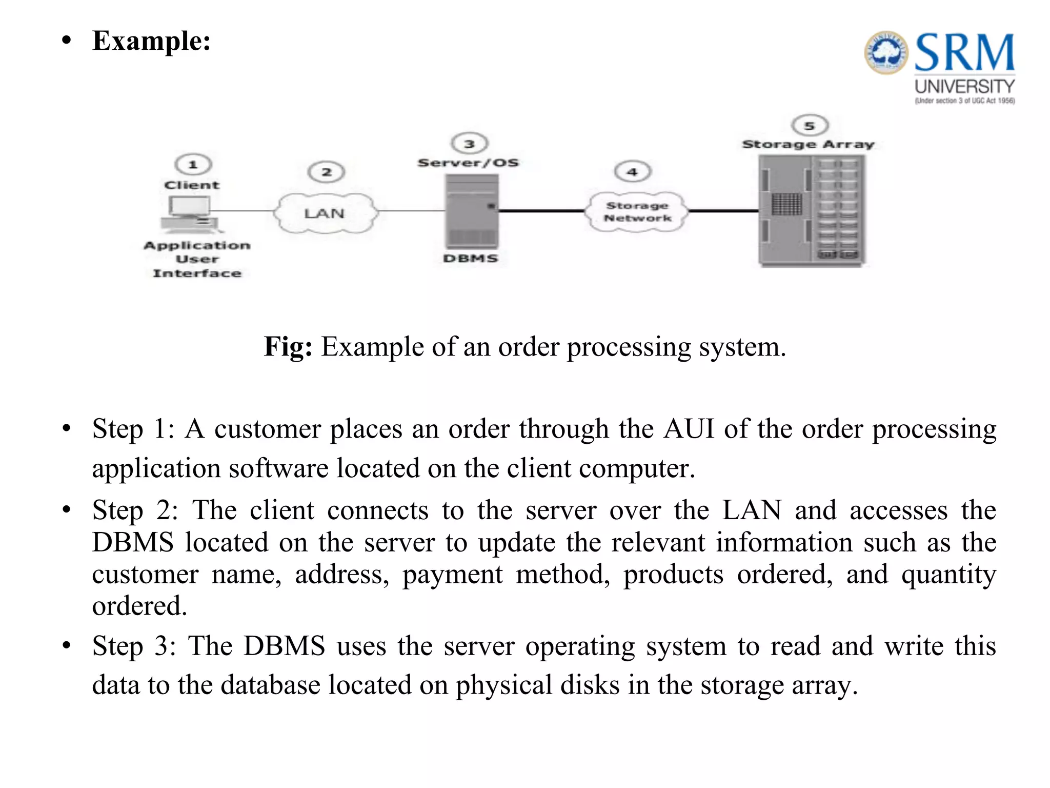
18CSE360T INFORMATION
STORAGE AND
MANAGEMENT
SRM INSTITUTE OF SCIENCE AND TECHNOLOGY,
CHENNAI.
Introduction to Information Storage Management, Evolution of
Storage
Architecture,Data Centre Infrastructure, Virtualization
and
Cloud
Computing, Keychallenges in managing Information, Data
Center
Environment: Application, Database Management System (DBMS), Host :
Connectivity, Storage, Disk Drive Components, Disk Drive Performance,
Intelligent Storage System, Components of an Intelligent Storage System,
Storage Provisioning,Types of Intelligent Storage Systems,Creation
of Virtual storage machine, Navigation of storage system .
UNIT – I
Introduction to Information Storage
Management
• Information is increasingly important in our daily lives. We have become information
dependents of the twenty-first century, living in an on-command, on-demand world that
means we need information when and where it is required.
• We access the Internet every day to perform searches, participate in social networking,
send and receive e-mails, share pictures and videos, and use scores of other applications.
• Equipped with a growing number of content-generating devices, more information is
created by individuals than by organizations (including business, governments,
non-profits and so on).
• Information created by individuals gains value when shared with others. When created,
information resides locally on devices, such as cell phones, smartphones, tablets,
cameras, and laptops. To be shared, this information needs to be uploaded to central
data repositories (data centers) via networks.
• Although the majority of information is created by
individuals, it is stored and managed by a relatively small
number of organizations.
Information Storage
• Businesses use data to derive information that is critical to their day-to-day
operations. Storage is a repository that enables users to store and retrieve
this digital data.
Data
• Data is a collection of raw facts from which conclusions may be drawn.
Handwritten letters, a printed book, a family photograph, a movie on video
tape, printed and duly signed copies of mortgage papers, a bank’s ledgers,
and an account holder’s passbooks are all examples of data.
• The data can be generated using a computer and stored in strings of 0s and
1s, Data in this form is called digital data and is accessible by the user only
after it is processed by a computer.
The factors that have contributed to the growth of digital data:
• Increase in data processing capabilities: Modern-day computers provide a significant increase in
processing and storage capabilities. This enables the conversion of various types of content and media from
conventional forms to digital formats.
• Lower cost of digital storage: Technological advances and decrease in the cost of storage devices have
provided low-cost solutions and encouraged the development of less expensive data storage devices. This cost
benefit has increased the rate at which data is being generated and stored.
• Affordable and faster communication technology: The rate of sharing digital data is now much faster than
traditional approaches. A handwritten letter may take a week to reach its destination, whereas it only takes a
few seconds for an e‑mail message to reach its recipient.
Types of Data
• Data can be classified as structured or unstructured based on how it is stored and
managed. Structured data is organized in rows and columns in a rigidly defined format
so that applications can retrieve and process it efficiently. Structured data is typically
stored using a database management system (DBMS).
• Data is unstructured if its elements cannot be stored in rows and columns, and is
therefore difficult to query and retrieve by business applications. For example, customer
contacts may be stored in various forms such as sticky notes, e-mail messages, business
cards, or even digital format files such as .doc, .txt, and .pdf.
Information
• Information is the intelligence and knowledge derived from data. Data,
whether structured or unstructured, does not fulfil any purpose for
individuals or businesses unless it is presented in a meaningful form.
Businesses need to analyze data for it to be of value.
• Effective data analysis not only extends its benefits to existing businesses,
but also creates the potential for new business opportunities by using the
information in creative ways.
Storage
• Data created by individuals or businesses must be stored so that it is easily
accessible for further processing. In a computing environment, devices
designed for storing data are termed storage devices or simply storage.
• Devices such as memory in a cell phone or digital camera, DVDs,
CD-ROMs, and hard disks in personal computers are examples
Evolution of Storage Technology and
Architecture
https://www.frontierinternet.com/gateway/data-storage-timeline/
• Historically, organizationshad centralized computers (mainframe) and
information storage devices (tape reels and disk packs) in their data center.
The evolution of open systems and the affordability and ease of deployment
that they offer made it possible for business units/departments to have their
own servers and storage. In earlier implementations of open systems, the
storage was typically internal to the server.
• Originally, there were very limited policies and processes for managing the
servers and the data created. To overcome these challenges, storage
technology evolved from non-intelligent internal storage to intelligent
networked storage
.
The technology evolution includes:
• Redundant Array of Independent Disks (RAID): This technology was developed to
address the cost, performance, and availability requirements of data. It continues to evolve
today and is used in all storage architectures such as DAS, SAN, and so on.
• Direct-attached storage (DAS): This type of storage connects directly to a server (host) or
a group of servers in a cluster. Storage can be either internal or external to the server.
External DAS alleviated the challenges of limited internal storage capacity.
• Storage area network (SAN): This is a dedicated, high-performance Fibre Channel (FC)
network to facilitate block-level communication between servers and storage. Storage is
partitioned and assigned to a server for accessing its data. SAN offers scalability,
availability, performance, and cost benefits compared to DAS.
• Network-attached storage (NAS): This is dedicated storage for file serving applications.
Unlike a SAN, it connects to an existing communication network (LAN) and provides file
access to heterogeneous clients. Because it is purposely built for providing storage to file
server applications, it offers higher scalability, availability, performance, and cost benefits
compared to general purpose file servers.
• Internet Protocol SAN (IP-SAN): One of the latest evolutions in storage architecture,
IP-SAN is a convergence of technologies used in SAN and NAS. IP-SAN provides
block-level communication across a local or wide area network (LAN or WAN), resulting
in greater consolidation and availability of data.
Data Center Infrastructure
• Organizations maintain data centers to provide centralized
data processing capabilities across the enterprise.
• Data centers store and manage large amounts of mission-critical
data.
• The data center infrastructure includes :
1) computers,
2) storage systems,
3) network devices,
4) dedicated power backups,
5) and environmental controls (such as air conditioning and fire
suppression).
Core Elements
Five core elements are essential for the basic functionality of a data center:
• Application: An application is a computer program that provides the logic
for computing operations. Applications, such as an order processing system,
can be layered on a database, which in turn uses operating system services to
perform read/write operations to storage devices.
• Database: More commonly, a database management system (DBMS)
provides a structured way to store data in logically organized tables that are
interrelated. A DBMS optimizes the storage and retrieval of data.
• Server and operating system: A computing platform that runs applications
and databases.
• Network: A data path that facilitates communication between clients and
servers or between servers and storage.
• Storage array: A device that stores data persistently for subsequent use.
• Example:
Fig: Example of an order processing system.
• Step 1: A customer places an order through the AUI of the order processing
application software located on the client computer.
• Step 2: The client connects to the server over the LAN and accesses the
DBMS located on the server to update the relevant information such as the
customer name, address, payment method, products ordered, and quantity
ordered.
• Step 3: The DBMS uses the server operating system to read and write this
data to the database located on physical disks in the storage array.
• Step 4: The Storage Network provides the communication link
between the server and the storage array and transports the read or
write commands between them.
• Step 5: The storage array, after receiving the read or write commands
from the server, performs the necessary operations to store the data on
physical disks.
Key Requirements for Data Center Elements
• Uninterrupted operation of data centers is critical to the survival and
success of a business. It is necessary to have a reliable infrastructure
that ensures data is accessible at all times.
• Availability: All data center elements should be designed to ensure accessibility. The
inability of users to access data can have a significant negative impact on a business.
• Security: Polices, procedures, and proper integration of the data center core elements
that will prevent unauthorized access to information must be established. In addition to
the security measures for client access, specific mechanisms must enable servers to
access only their allocated resources on storage arrays.
• Scalability: Data center operations should be able to allocate additional processing
capabilities or storage on demand, without interrupting business operations. Business
growth often requires deploying more servers, new applications, and additional
databases. The storage solution should be able to grow with the business.
• Performance: All the core elements of the data center should be able to provide
optimal performance and service all processing requests at high speed. The
infrastructure should be able to support performance requirements.
• Data integrity: Data integrity refers to mechanisms such as error correction codes or parity bits which ensure
that data is written to disk exactly as it was received. Any variation in data during its retrieval implies
corruption, which may affect the operations of the organization.
• Capacity: Data center operations require adequate resources to store and process large amounts of data
efficiently. When capacity requirements increase, the data center must be able to provide additional capacity
without interrupting availability, or, at the very least, with minimal disruption. Capacity may be managed by
reallocation of existing resources, rather than by adding new resources.
• Manageability: A data center should perform all operations and activities in the most efficient manner.
Manageability can be achieved through automation and the reduction of human (manual) intervention in
common tasks.
Managing Storage Infrastructure
• Managing a modern, complex data center involves many tasks. Key management activities include:
• Monitoring is the continuous collection of information and the review of the entire data center
infrastructure.The aspects of a data center that are monitored include security, performance, accessibility, and
capacity.
• Reporting is done periodically on resource performance, capacity, and
utilization. Reporting tasks help to establish business justifications
and chargeback of costs associated with data center operations.
• Provisioning is the process of providing the hardware, software, and
other resources needed to run a data center. Provisioning activities
include capacity and resource planning. Capacity planning ensures
that the user’s and the application’s future needs will be addressed in
the most cost-effective and controlled manner. Resource planning is
the process of evaluating and identifying required resources, such as
personnel, the facility (site), and the technology.
Cloud Computing
Definition of Cloud Computing
Cloud Computing allows customers to utilize resources (e.g., networks,
servers, storage, applications, and services) `which are hosted by service
providers. Typically this is done on a pay-per-use own charge-per-use basis.
Characteristics of Cloud Computing
• On-demand self-service
• Broad network access
• Resource pooling
• Rapid elasticity
• Measured service
Infrastructure as a Service (IaaS).
• A service model that involves outsourcing the basic infrastructure used to support operations--including storage, hardware,
servers, and networking components.
• The service provider owns the infrastructure equipment and is responsible for housing, running, and maintaining it. The
customer typically pays on a per-use basis.
• Example: DigitalOcean, Linode, Rackspace, Amazon Web Services (AWS), Cisco Metapod, Microsoft Azure, Google Compute
Engine (GCE)
Platform as a Service (PaaS)
• A service model that involves outsourcing the basic infrastructure and platform (Windows, Unix)
• PaaS facilitates deploying applications without the cost and complexity of buying and managing the underlying hardware
and software where the applications are hosted.
• Example : AWS Elastic Beanstalk, Windows Azure, Heroku, Force.com, Google App Engine, Apache Stratos, OpenShift
Software as a Service (SaaS).
• Also referred to as “software on demand,” this service model involves outsourcing the infrastructure, platform, and
software/applications.
• Typically, these services are available to the customer for a fee, pay-as-you-go, or a no charge model.
• Example : Google Apps, Dropbox, Salesforce, Cisco WebEx, Concur, GoToMeeting
Cloud Computing provides mainly three types of service models. such as
Cloud Computing provides mainly three types of Deployment models. such
as
❖ Private Cloud
❖ Public cloud
❖ Community cloud
❖ Hybrid cloud
Private Cloud
In a private cloud model, the cloud infrastructure is provisioned for
exclusive use by a single organization comprising multiple consumers
(for example, business units). It may be owned, managed, and
operated by the organization, a third party, or some combination of
them, and it may exist on or off premises.
Following are two variations to the private cloud model:
On-premise private cloud:
The on-premise private cloud, also known as internal cloud, is hosted
by an organization within its own data centers
Externally hosted private :
This type of private cloud is hosted external to an organization (and is
managed by a thirdparty organization.
Private Cloud
Public Cloud
In a public cloud model, the cloud infrastructure is provisioned for
open use by the general public. It may be owned, managed, and
operated by a business, academic, or government organization, or
some combination of them. It exists on the premises of the cloud
provider.
Community Cloud
In a community cloud model, the cloud infrastructure is provisioned
for exclusive use by a specifi c community of consumers from
organizations that have sharedconcerns (for example, mission,
security requirements, policy, and compliance considerations).
• It may be owned, managed, and operated by one or more of the
organizations in the community, a third party, or some combination of
them, and it may exist on or off premises..
Hybrid Cloud
In a hybrid cloud model, the cloud infrastructure is a composition of
twoor more distinct cloud infrastructures (private,
community,or
standardized or proprietary technology thatenables data
public) thatremain unique entities,but are bound together by
and
application portability (for example, cloud bursting for load balancing
between clouds).
Enabling technologies of cloud computing
• Grid computing
• Utility computing
• Virtualization
• Service Oriented Architecture (SOA
Benefits and challenges of cloud
computing
Although there is growing acceptance of cloud computing, both the
cloud service consumers and providers have been facing some
challenges.
Challenges for Consumers
• Business-critical data requires protection and continuous monitoring of its
access. If the data moves to a cloud model other than an on-premise private
cloud, consumers could lose absolute control of their sensitive data.
• Although most of the cloud service providers offer enhanced data security,
consumers might not be willing to transfer control of their business-critical
data to the cloud.
• Cloud service providers might use multiple data centers located in
different countries to provide cloud services. They might replicate or
move data across these data centers to ensure high availability and
load distribution
• Consumers may or may not know in which country their data is
stored. Some cloud service providers allow consumers to select the
location for storing their data..
• Cloud services can be accessed from anywhere via a network.
However, network latency increases when the cloud infrastructure is
not close to the access point. A high network latency can either
increase the application response time or cause the application to
timeout.
• Another challenge is that cloud platform services may not support
consumers’desired applications. For example, a service provider
might not be able to support highly specialized or proprietary
environments, such as compatible OSs and preferred programming
languages, required to develop and run the consumer’s application.
Also, a mismatch between hypervisors could impact migration of
virtual machines into or between clouds.
• Another challenge is vendor lock-in: the difficulty for consumers to
change their cloud service provider. A lack of interoperability
between the APIs of different cloud service providers could also
create complexity and high migration costs when moving from one
service provider to another.
Challenges for Providers
• Cloud service providers usually publish a service-level agreement
(SLA) so that their consumers know about the availability of service,
quality of service, downtime compensation, and legal and
regulatory clauses.
• Alternatively, customer-specific SLAs may be signed between a
cloud service provider and a consumer.
• SLAs typically mention a penalty amount if cloud service providers
fail to provide the service levels. Therefore, cloud service providers
must ensure that they have adequate resources to provide the required
levels of services.
• Because the cloud resources are distributed and service demands
fluctuate, it is a challenge for cloud service providers to provision
physical resources for peak demand of all consumers and estimate the
actual cost of providing the services.
• Many software vendors do not have a cloud-ready software licensing
model. Some of the software vendors offer standardized cloud
licenses at a higher price compared to traditional licensing models.
The cloud software licensing complexity has been causing challenges
in deploying vendor software in the cloud. This is also a challenge to
the consumer.
• Cloud service providers usually offer proprietary APIs to access their
cloud. However, consumers might want open APIs or standard APIs
to become the tenant of multiple clouds. This is a challenge for cloud
service providers because this requires agreement among cloud
service providers.
Benefits of cloud computing:
• Scalability and elasticity
• Accessibility and reliability
• Cost and operational efficiency
• Rapid and flexible deployment
• Security and compatibility
Challenges of cloud computing:
• Internet connectivity
• Financial commitment
• Data security and protection
• Readiness and maturity
• Interoperability
Virtualization
• Virtualization is the "creation of a virtual (rather than actual) version of something,
such as a server, a desktop, a storage device, an operating system or network
resources".
• Virtualization plays a very important role in the cloud computing technology,
normally in the cloud computing, users share the data present in the clouds like
application etc, but actually with the help of virtualization users shares the
Infrastructure.
• The main usage of Virtualization Technology is to provide the applications with the
standard versions to their cloud users, suppose if the next version of that application
is released, then cloud provider has to provide the latest version to their cloud users
and practically it is possible because it is more expensive.
• To overcome this problem we use basically virtualization technology, By using
virtualization, all severs and the software application which are required by other
cloud providers are maintained by the third party people, and the cloud providers has
to pay the money on monthly or annual basis.
Types of Virtualization
❖ Hardware Virtualization.
❖ Operating system Virtualization.
❖ Server Virtualization.
❖ Storage Virtualization.
Hardware Virtualization.
• When the virtual machine software or virtual machine manager
(VMM) is directly installed on the hardware system is known as
hardware virtualization.
• The main job of hypervisor is to control and monitoring the processor,
memory and other hardware resources.
• Aftervirtualization of hardware system we can install
different operating system on it and run different applications on
those OS.
• Usage:
• Hardware virtualization is mainly done for the server platforms,
because controlling virtual machines is much easier than controlling a
physical server.
Key Challenges in Managing Information
• In order to frame an effective information management
policy, businesses need to consider the following key
challenges of information management:
• Exploding digital universe: The rate of information growth is
increasing exponentially. Duplication of data to ensure high
availability and repurposing has also contributed to the
multifold increase of information growth.
• Increasing dependency on information: The strategic use of
information plays an important role in determining the success of a
business and provides competitive advantages in the marketplace.
• Changing value of information: Information that is valuable today
may become less important tomorrow. The value of information
often changes over time.
Data Center Environment:
Application
• An application is a computer program that provides the logic for
computing operations. The application sends requests to the
underlying operating system to perform read/write (R/W) operations
on the storage devices. Applications can be layered on the database,
which in turn uses the OS services to perform R/W operations on
the storage devices.
• Applications deployed in a data center environment are commonly
categorized as business applications, infrastructure management
applications, data protection applications, and security applications.
Some examples of these applications are e-mail, enterprise
resource planning (ERP), decision support system (DSS), resource
management, backup, authentication and antivirus applications,
and so on.
APPLICATION VIRTUALIZATION
• Application virtualization breaks the dependency between the application
and the underlying platform (OS and hard- ware). Application virtualization
encapsulates the application and the required OS resources within a
virtualized container. This technology provides the ability to deploy
applications without making any change to the underlying OS, file system,
or registry of the computing platform on which they are deployed.
Because virtualized applications run in an isolated environment, the
underlying OS and other applications are protected from potential
corruptions.
• There are many scenarios in which conflicts might arise if multiple
applications or multiple versions of the same application are installed on the
same computing plat- form. Application virtualization eliminates this
conflict by isolating different versions of an application and the associated
O/S resources.
• The characteristics of I/Os (Input/Output) generated by the application
influence the overall performance of storage system and storage solution
designs.
Database Management System (DBMS)
• A database is a structured way to store data in logically organized tables
that are interrelated. A database helps to optimize the storage and retrieval
of data. A DBMS controls the creation, maintenance, and use of a database.
• The DBMS processes an application’s request for data and instructs
the operating system to transfer the appropriate data from the storage.
Advantages of DBMS:
1.Data Independence.
2.Efficient Data Access.
3.Data Integrity and security.
4.Data administration.
5.Concurrent access and Crash recovery.
6.Reduced Application Development Time.
Applications
• Banking: all transactions
• Airlines: reservations, schedules
• Universities: registration, grades
• Sales: customers, products, purchases
• Online retailers: order tracking, customized recommendations
• Manufacturing: production, inventory, orders, supply chain
• Human resources: employee records, salaries, tax deductions
Host : Connectivity, Storage
HOST
• The computers on which these applications run are referred to as hosts or compute
systems. Hosts can be physical or virtual machines. A compute virtualization software
enables creating virtual machines on top of a physical compute infrastructure.
• Compute virtualization and virtual machines are discussed later in this chapter.
Examples of physical hosts include desktop computers, servers or a cluster of servers,
laptops, and mobile devices.
• A host consists of CPU, memory, I/O devices, and a collection of software to perform
computing operations. This software includes the operating system, file system,
logical volume manager, device drivers, and so on. This software can be installed as
separate entities or as part of the operating system.
• The CPU consists of four components: Arithmetic Logic Unit (ALU), control unit,
registers, and L1 cache. There are two types of memory on a host, Random Access
Memory (RAM) and Read-Only Memory (ROM). I/O devices enable communication
with a host. Examples of I/O devices are keyboard, mouse, monitor, etc.
• Software runs on a host and enables processing of input and output (I/O) data. The
following section details various software components that are essential parts of a host
system.
• Connectivity refers to the interconnection between hosts or between a host and
peripheral devices, such as printers or storage devices.
• Connectivity and communication between host and storage are enabled using
physical components and interface protocols.
Physical Components of Connectivity
• The physical components of connectivity are the hardware elements that
connect the host to storage. Three physical components of connectivity
between the host and storage are the host interface device, port, and cable.
• A host interface device or host adapter connects a host to other hosts and
storage devices. Examples of host interface devices are host bus adapter
(HBA) and network interface card (NIC).
• Host bus adaptor is an application-specific integrated circuit (ASIC) board
that performs I/O interface functions between the host and storage,
relieving the CPU from additional I/O processing workload. A host
typically contains multiple HBAs.
• A port is a specialized outlet that enables connectivity between the host
and external devices.
• An HBA may contain one or more ports to connect the host to the storage device.
Cables connect hosts to internal or external devices using copper or fiber optic
Physical components of connectivity
Storage
• Storage is a core component in a data center. A storage device uses magnetic,
optic, or solid state media. Disks, tapes, and diskettes use magnetic media,
whereas CD/DVD uses optical media for storage. Removable Flash memory or
Flash drives are examples of solid state media.
• Data is stored on the tape linearly along the length of the tape. Search and retrieval
of data are done sequentially, and it invariably takes several seconds to access the
data.
• As a result, random data access is slow and time-consuming. This limits tapes as a
viable option for applications that require real-time, rapid access to data.
• In a shared computing environment, data stored on tape cannot be
accessed by multiple applications simultaneously, restricting its use
to one application at a time.
• On a tape drive, the read/write head touches the tape surface, so
the tape degrades or wears out after repeated use.
• The storage and retrieval requirements of data from the tape and
the overhead associated with managing the tape media are
significant.
• storage is popular in small, single-user computing environments. It
is frequently used by individuals to store photos or as a backup
medium on personal or laptop computers.
• It is also used as a distribution medium for small applications, such
as games, or as a means to transfer small amounts of data from one
computer system to another.
• computers for storing and accessing data for
performance-intensive, online applications. Disks support rapid
Disk Drive Components
• The key components of a hard disk drive are platter, spindle,
read-write head, actuator arm assembly, and controller
• I/O operations in a HDD are performed by rapidly moving the arm
across the rotating flat platters coated with magnetic particles.
• Data is transferred between the disk controller and magnetic
platters through the read-write (R/W) head which is attached to the
arm.
• Data can be recorded and erased on magnetic platters any number of
times. Following sections detail the different components of the disk
drive, the mechanism for organizing and storing data on disks, and
the factors that affect disk performance
Platter
• A typical HDD consists of one or more flat circular disks called platters .The
data is recorded on these platters in binary codes (0s and 1s). The set of
rotating platters is sealed in a case, called the Head Disk Assembly (HDA).
• A platter is a rigid, round disk coated with magnetic material on both
surfaces (top and bottom). The data is encoded by polarizing the
magnetic area, or domains, of the disk surface.
• Data can be written to or read from both surfaces of the platter. The number
of platters and the storage capacity of each platter determine the total
capacity of the drive.
Spindle
• A spindle connects all the platters and is connected to a motor. The motor
of the spindle rotates with a constant speed.
• The disk platter spins at a speed of several thousands of revolutions per
minute (rpm). Common spindle speeds are 5,400 rpm, 7,200 rpm, 10,000
rpm, and 15,000 rpm. The speed of the platter is increasing with
improvements in technology, although the extent to which it can be
improved is limited.
Read/Write Head
• Read/Write (R/W) heads, read and write data from or to platters. Drives have
two R/W heads per platter, one for each surface of the platter. The R/W head
changes the magnetic polarization on the surface of the platter when writing
data.
• While reading data, the head detects the magnetic polarization on the surface
of the platter. During reads and writes, the R/W head senses the magnetic
polarization and never touches the surface of the platter.
• When the spindle is rotating, there is a microscopic air gap maintained
between the R/W heads and the platters, known as the head flying height.
• This air gap is removed when the spindle stops rotating and the R/W head
rests on a special area on the platter near the spindle. This area is called
the landing zone. The landing zone is coated with a lubricant to reduce
friction between the head and the platter.
• The logic on the disk drive ensures that heads are moved to the landing
zone before they touch the surface. If the drive malfunctions and the R/W
head accidentally touches the surface of the platter outside the landing
zone, a head crash occurs.
• In a head crash, the magnetic coating on the platter is scratched and may
cause damage to the R/W head. A head crash generally results in data loss.
Actuator Arm Assembly
• R/W heads are mounted on the actuator arm assembly, which
positions the R/W head at the location on the platter where
the data needs to be written or read .
• The R/W heads for all platters on a drive are attached to
one actuator arm assembly and move across the platters
simultaneously.
Drive Controller Board
• The controller is a printed circuit board, mounted at the bottom of a
disk drive. It consists of a microprocessor, internal memory, circuitry,
and firmware.
• The firmware controls the power to the spindle motor and the speed of the
motor. It also manages the communication between the drive and the
host.
• In addition, it controls the R/W operations by moving the actuator arm and
switching between different R/W heads, and performs the optimization of
data access.
Physical Disk Structure
• Data on the disk is recorded on tracks, which are concentric
rings on the platter around the spindle, The tracks are
numbered, starting from zero, from the outer edge of the
platter.
• The number of tracks per inch (TPI) on the platter (or the track
density) measures how tightly the tracks are packed on a
platter.
• The track and sector structure is written on the platter by the drive
manufacturer using a low-level formatting operation. The number of sectors
per track varies according to the drive type.
• The first personal computer disks had 17 sectors per track. Recent disks have
a much larger number of sectors on a single track. There can be thousands of
tracks on a platter, depending on the physical dimensions and recording
density of the platter.
• A cylinder is a set of identical tracks on both surfaces of each drive platter.
The location of R/W heads is referred to by the cylinder number, not by
the track number
Zoned Bit Recording
• Platters are made of concentric tracks; the outer tracks can
hold more data than the inner tracks because the outer tracks
are physically longer than the inner tracks.
• On older disk drives, the outer tracks had the same number of
sectors as the inner tracks, so data density was low on the
outer tracks. This was an inefficient use of the available
space.
• Zoned bit recording uses the disk efficiently. this mechanism
groups tracks into zones based on their distance from the
center of the disk. The zones are numbered, with the
outermost zone being zone 0.
• An appropriate number of sectors per track are assigned to each zone, so a zone
near the center of the platter has fewer sectors per track than a zone on the outer
edge. However, tracks within a particular zone have the same number of sectors.
Logical Block Addressing
• Earlier drives used physical addresses consisting of the cylinder,
head, and sector (CHS) number to refer to specific locations on the
disk, and the host operating system had to be aware of the geometry
of each disk used.
• Logical block addressing (LBA), simplifies addressing by using a linear
address to access physical blocks of data. The disk controller translates
LBA to a CHS address, and the host needs to know only the size of the disk
drive in terms of the number of blocks.
Disk Drive Performance
• A disk drive is an electromechanical device that governs the overall
performance of the storage system environment.
• The various factors that affect the performance of disk drives are discussed
in this section.
Disk Service Time
• Disk service time is the time taken by a disk to complete an I/O request.
Components that contribute to service time on a disk drive are seek time,
rotational latency, and data transfer rate.
Seek Time
• The seek time (also called access time) describes the time taken to position
the R/W heads across the platter with a radial movement (moving along the
radius of the platter). In other words, it is the time taken to reposition and
settle the arm and the head over the correct track. The lower the seek time,
the faster the I/O operation. Disk vendors publish the following seek time
specifications:
• Full Stroke: The time taken by the R/W head to move across the entire
width of the disk, from the innermost track to the outermost track.
• Average: The average time taken by the R/W head to move from one
random track to another, normally listed as the time for one-third of a full
stroke.
• Track-to-Track: The time taken by the R/W head to move between
adjacent tracks.
Rotational Latency
• To access data, the actuator arm moves the R/W head over the platter to a
particular track while the platter spins to position the requested sector under
the R/W head. The time taken by the platter to rotate and position the data
under the R/W head is called rotational latency. This latency depends on the
rotation speed of the spindle and is measured in milliseconds.
Data Transfer Rate
• The data transfer rate (also called transfer rate) refers to the average
amount of data per unit time that the drive can deliver to the HBA.
• In a read operation, the data first moves from disk platters to R/W
heads, and then it moves to the drive’s internal buffer.
• Finally, data moves from the buffer through the interface to the host
HBA. In a write operation, the data moves from the HBA to the
internal buffer of the disk drive through the drive’s interface.
• The data then moves from the buffer to the R/W heads. Finally, it
moves from the R/W heads to the platters.
Internal transfer rate is the speed at which data moves from a single
track of a platter’s surface to internal buffer (cache) of the disk.
Internal transfer rate takes into account factors such as the seek time.
External transfer rate is the rate at which data can be moved
through the interface to the HBA. External transfer rate is
generally the advertised speed of the interface, such as 133 MB/s
for ATA.
Intelligent Storage Systems
• Business critical applications require high levels of performance,
availability, security, and scalability. A disk drive is a core element of
storage that governs the performance of any storage system.
• Some of the older disk array technologies could not overcome
performance constraints due to the limitations of disk drives and their
mechanical components.
• RAID technology made an important contribution to enhancing
storage performance and reliability, but disk drives, even with a RAID
implementation, could not meet the performance requirements of
today’s applications.
• With advancements in technology, a new breed of storage solutions,
known as intelligent storage systems, has evolved. These intelligent
storage systems are feature-rich RAID arrays that provide highly
optimized I/O processing capabilities.
• These intelligent storage systems are feature-rich RAID arrays
that provide highly optimized I/O processing capabilities.
• These storage systems are configured with a large amount of memory
(called cache) and multiple I/O paths and use sophisticated
algorithms to meet the requirements of performance sensitive
applications.
• These arrays have an operating environment that intelligently
and optimally handles the management, allocation, and
utilization of storage resources.
• Support for flash drives and other modern-day technologies, such as
virtual storage provisioning and automated storage tiering, has
added a new dimension to storage system performance, scalability,
and availability.
Components of an Intelligent Storage System
• An intelligent storage system consists of four key components: front end,
cache, back end, and physical disks. An I/O request received from the host at
the front-end port is processed through cache and back end, to enable storage
and retrieval of data from the physical disk.
• A read request can be serviced directly from cache if the requested data
is found in the cache. In modern intelligent storage systems, front end,
cache, and back end are typically integrated on a single board (referred to
as a storage processor or storage controller).
Front End
• The front end provides the interface between the storage
system and the host. It consists of two components: front-end
ports and front-end controllers.
• Typically, a front end has redundant controllers for high
availability, and each controller contains multiple ports
that enable large numbers of hosts to connect to the
intelligent storage system.
• Each front-end controller has processing logic that executes
the appropriate transport protocol, such as Fibre Channel,
iSCSI, FICON, or FCoE for storage connections.
• Front-end controllers route data to and from cache via the
internal data bus. When the cache receives the write data, the
controller sends an acknowledgment message back to the
host.
Cache
• Cache is semiconductor memory where data is placed temporarily to reduce
the time required to service I/O requests from the host
• Cache improves storage system performance by isolating hosts from the
mechanical delays associated with rotating disks or hard disk drives (HDD).
• Rotating disks are the slowest component of an intelligent storage system.
Data access on rotating disks usually takes several millisecond because of
seek time and rotational latency.
• Accessing data from cache is fast and typically takes less than a
millisecond. On intelligent arrays, write data is first placed in cache and
then written to disk.
Structure of Cache
• Cache is organized into pages, which is the smallest unit of cache
allocation. The size of a cache page is configured according to the
application I/O size.
• Cache consists of the data store and tag RAM. The data store holds the data
whereas the tag RAM tracks the location of the data in the data store and in
the disk.
• Entries in tag RAM indicate where data is found in cache and where
the data belongs on the disk. Tag RAM includes a dirty bit flag, which
indicates whether the data in cache has been committed to the disk.
• It also contains time-based information, such as the time of last
access, which is used to identify cached information that has not
been accessed for a long period and may be freed up.
Read Operation with Cache
• When a host issues a read request, the storage controller reads the tag
RAM to determine whether the required data is available in cache.
• If the requested data is found in the cache, it is called a read cache
hit or read hit and data is sent directly to the host, without any disk
operation .
• This provides a fast response time to the host (about a millisecond). If
the requested data is not found in cache, it is called a cache miss and
the data must be read from the disk .
• The back end accesses the appropriate disk and retrieves the requested
data. Data is then placed in cache and finally sent to the host through
the front end. Cache misses increase the I/O response time.
• A prefetch or read-ahead algorithm is used when read requests are sequential. In a sequential
read request, a contiguous set of associated blocks is retrieved. Several other blocks that have
not yet been requested by the host can be read from the disk and placed into cache in advance.
• When the host subsequently requests these blocks, the read operations will be read hits. This
process significantly improves the response time experienced by the host. The intelligent storage
system offers fixed and variable pre fetch sizes. In fixed pre f etch, the intelligent storage system
pre fetches a fixed amount of data. It is most suitable when host I/O sizes are uniform.
• In variable pre fetch, the storage system pre fetches an amount of data in multiples
of the size of the host request. Maximum pre fetch limits the number of data blocks
that can be pre fetched to prevent the disks from being rendered busy with pre
fetch at the expense of other I/Os.
• Read performance is measured in terms of the read hit ratio, or the hit rate,
usually expressed as a percentage. This ratio is the number of read hits with
respect to the total number of read requests. A higher read hit ratio improves the
read performance.
Write Operation with Cache
• Write operations with cache provide performance advantages over writing directly
to disks. When an I/O is written to cache and acknowledged, it is completed in far
less time (from the host’s perspective) than it would take to write directly to disk.
• Sequential writes also offer opportunities for optimization because many smaller
writes can be coalesced for larger transfers to disk drives with the use of cache.
A write operation with cache is implemented in the following ways:
• Write-back cache: Data is placed in cache and an acknowledgment is sent to the
host immediately. Later, data from several writes are committed (de-staged) to the
disk. Write response times are much faster because the write operations are
isolated from the mechanical delays of the disk. However, uncommitted data is at
risk of loss if cache failures occur.
Write-through cache: Data is placed in the cache and
immediately written to the disk, and an acknowledgment is sent
to the host.
Because data is committed to disk as it arrives, the risks of data loss
are low, but the write-response time is longer because of the
disk operations.
Cache Implementation
• Cache can be implemented as either dedicated cache or global cache.
With dedicated cache, separate sets of memory locations are
reserved for reads and writes.
• In global cache, both reads and writes can use any of the available
memory addresses. Cache management is more efficient in a global
cache implementation because only one global set of addresses has
to be managed.
Cache Management
• Cache is a finite and expensive resource that needs proper
management. Even though modern intelligent storage systems
come with a large amount of cache, when all cache pages are
filled, some pages have to be freed up to accommodate new
data and avoid performance degradation.
• Various cache management algorithms are implemented in
intelligent storage systems to proactively maintain a set of
free pages and a list of pages that can be potentially freed up
whenever required.
Least Recently Used (LRU): An algorithm that continuously monitors
data access in cache and identifies the cache pages that have not
been accessed for a long time.
• LRU either frees up these pages or marks them for reuse. This
algorithm is based on the assumption that data that has not
been accessed for a while will not be requested by the host.
Most Recently Used (MRU):
• This algorithm is the opposite of LRU, where the pages that have
been accessed most recently are freed up or marked for reuse. This
algorithm is based on the assumption that recently accessed data
may not be required for a while.
Flushing :
• Flushing is the process that commits data from cache to the
disk. On the basis of the I/O access rate and pattern, high
and low levels called watermarks are set in cache to manage
the flushing process.
• High watermark (HWM) is the cache utilization level at
which the storage system starts high-speed flushing of cache
data.
• Low watermark (LWM) is the point at which the
storage system stops flushing data to the disks.
• Idle flushing: Occurs continuously, at a modest rate, when the
cache utilization level is between the high and low watermark
• High watermark flushing: Activated when cache utilization hits the
high watermark. The storage system dedicates some additional
resources for flushing. This type of flushing has some impact on I/O
processing.
• Forced flushing: Occurs in the event of a large I/O burst when cache
reaches 100 percent of its capacity, which significantly affects the I/O
response time. In forced flushing, system flushes the cache on priority
by allocating more resources.
Storage Provisioning
• Storage provisioning is the process of assigning storage resources to
hosts based on capacity, availability, and performance requirements
of applications running on the hosts.
• Storage provisioning can be performed in two ways: traditional and
virtual. Virtual provisioning leverages virtualization technology for
provisioning storage for applications.
Traditional Storage Provisioning
• In traditional storage provisioning, physical disks are logically
grouped together and a required RAID level is applied to form a
set, called a RAID set.
• The number of drives in the RAID set and the RAID level
determine the availability, capacity, and performance of the RAID
set.
• It is highly recommend that the RAID set be created from drives
of the same type, speed, and capacity to ensure maximum usable
capacity, reliability, and consistency in performance.
• Each logical unit created from the RAID set is assigned a unique ID,
called a logical unit number (LUN).
• LUNs hide the organization and composition of the RAID set from
the hosts. LUNs created by traditional storage provisioning methods
are also referred to as thick LUNs to distinguish them from the LUNs
created by virtual provisioning methods.
• When a LUN is configured and assigned to a non-virtualized host, a
bus scan is required to identify the LUN.
• This LUN appears as a raw disk to the operating system. To make this
disk usable, it is formatted with a file system and then the file system
is mounted.
• In a virtualized host environment, the LUN is assigned to the
hypervisor, which recognizes it as a raw disk. This disk is configured
with the hypervisor file system, and then virtual disks are created on
it. Virtual disks are files on the hypervisor file system.
• Virtual machines can also access a LUN directly on the storage system.
In this method the entire LUN is allocated to a single virtual machine.
• Storing data in this way is recommended when the applications running on
the virtual machine are response-time sensitive, and sharing storage with
other virtual machines may impact their response time.
• The direct access method is also used when a virtual machine is
clustered with a physical machine. In this case, the virtual machine is
required to access the LUN that is being accessed by the physical
machine.
• MetaLUN is a method to expand LUNs that require additional
capacity or performance. A metaLUN can be created by combining
two or more LUNs. A metaLUN consists of a base LUN and one
or more component LUNs. MetaLUNs can be either concatenated
or striped.
• Striped expansion restripes the base LUN’s data across the base
LUN and component LUNs. In striped expansion, all LUNs must be
of the same capacity and RAID level. Striped expansion provides
improved performance due to the increased number of drives being
striped.
Virtual Storage Provisioning
• Virtual provisioning enables creating and presenting a LUN with
more capacity than is physically allocated to it on the storage array.
The LUN created using virtual provisioning is called a thin LUN to
distinguish it from the traditional LUN.
• Thin LUNs do not require physical storage to be completely allocated
to them at the time they are created and presented to a host. Physical
storage is allocated to the host “on-demand” from a shared pool of
physical capacity.
• A shared pool consists of physical disks. A shared pool in virtual
provisioning is analogous to a RAID group, which is a collection of
drives on which LUNs are created.
• Similar to a RAID group, a shared pool supports a single RAID
protection level. However, unlike a RAID group, a shared pool might
contain large numbers of drives. Shared pools can be homogeneous
(containing a single drive type) or heterogeneous (containing mixed
drive types, such as flash, FC, SAS, and SATA drives).
• Virtual provisioning enables more efficient allocation of storage to hosts.
Virtual provisioning also enables oversubscription, where more capacity is
presented to the hosts than is actually available on the storage array.
• Both shared pool and thin LUN can be expanded non disruptively as the
storage requirements of the hosts grow. Multiple shared pools can be created
within a storage array, and a shared pool may be shared by multiple thin
LUNs.
Comparison between Virtual and Traditional Storage Provisioning
• Administrators typically allocate storage capacity based on
anticipated storage requirements. This generally results in the over
provisioning of storage capacity, which then leads to higher costs and
lower capacity utilization.
• Administrators often over-provision storage to an application for
various reasons, such as, to avoid frequent provisioning of storage if
the LUN capacity is exhausted, and to reduce disruption to application
availability.
• Over provisioning of storage often leads to additional storage
acquisition and operational costs.
• Virtual provisioning addresses these challenges. Virtual provisioning
improves storage capacity utilization and simplifies storage
management.
LUN Masking
• LUN masking is a process that provides data access control by
defining which LUNs a host can access. The LUN masking
function is implemented on the storage array. This ensures
that volume access by hosts is controlled appropriately,
preventing unauthorized or accidental use in a shared
environment.
Types of Intelligent Storage Systems
• It consist of 2 categories: High-end storage systems,Midrange storage
systems.
• Traditionally, high-end storage systems have been implemented with
active- active configuration, whereas midrange storage systems have
been implemented with active-passive configuration.
• The distinctions between these two implementations are becoming
increasingly insignificant.
High-End Storage Systems
• High-end storage systems, referred to as active-active arrays, are
generally aimed at large enterprise applications. These systems are
designed with a large number of controllers and cache memory.
• An active-active array implies that the host can perform I/Os to its
LUNs through any of the available controllers.
• To address enterprise storage needs, these arrays provide
the following capabilities:
– Large storage capacity
– Large amounts of cache to service host I/Os optimally
– Fault tolerance architecture to improve data availability
– Connectivity to mainframe computers and open systems hosts
– Availability of multiple front-end ports and interface protocols to
serve a large number of hosts
– Availability of multiple back-end controllers to manage
disk processing
– Scalability to support increased connectivity, performance,
and storage capacity requirements
– Ability to handle large amounts of concurrent I/Os from
a number of hosts and applications
– Support for array-based local and remote data replication
Midrange Storage Systems
• Midrange storage systems are also referred to as active-passive arrays and
are best suited for small- and medium-sized enterprise applications. They
also provide optimal storage solutions at a lower cost. In an active-passive
array, a host can perform I/Os to a LUN only through the controller that
owns the LUN.
• The host can perform reads or writes to the LUN only through the path to
controller A because controller A is the owner of that LUN. The path to
controller B remains passive and no I/O activity is performed through this
path.
• Midrange storage systems are typically designed with two
controllers, each of which contains host interfaces, cache,
RAID controllers, and interface to disk drives.
• Midrange arrays are designed to meet the requirements of small
and medium enterprise applications; therefore, they host less
storage capacity and cache than high-end storage arrays.
Creation of Virtual storage machine,
• Use CCI to create a virtual storage machine.
• To create a virtual storage machine, you add a resource group
and assign the model type and serial number of the virtualized
storage system to the resource group.
• If you issue the raidcom add resource command and specify the
model type and serial number of an existing virtual storage
machine, only the resource group is created on the existing virtual
storage machine. You can create a maximum of 1,023 resource
groups per virtual storage machine.
Before you begin
Information required when you create a virtual storage machine:
• Model type and serial number of the storage system to be virtualized
• Port/host group information of the LDEVs to be virtualized
(for example, CL1-A-1)
• LDEV IDs of the LDEVs to be virtualized
Procedure
1. Create a virtual storage machine by using the raidcom add
resource command.
• Example:
raidcom add resource -resource_name rsg_vir -virtual_type 20000
R700
where:
rsg_vir is the name of the new resource group that will contain
the virtualized resources.
200000 is the serial number of the virtual storage machine.
R700 is the model type of the virtual storage machine.
These model types are supported:
– R900F: VSP 5500, VSP 5100
– R900G: VSP 5100H, VSP 5500H
– R800: VSP G1x00, VSP F1500
– R700:
VSP
– R600: USP V
– RK600: USP VM
– M700: HUS VM
2. In the virtual storage machine, reserve the ID for the host group
that will be accessed by the host server.
• For example:
raidcom add resource -resource_name rsg_vir -port CL1-A-1
3. Delete the default virtual ID.
• By default, virtual IDs are set in the LDEVs in the storage system.
Delete the default virtual ID from the LDEV that you plan to use by
using the raidcom unmap resource command.
• For example:raidcom unmap resource -ldev_id 10:00
-virtual_ldev_id 10:00
4. Reserve the ID for the LDEV in the resource group.
• In the resource group, reserve the LDEV ID for the LDEV that
you plan to use in the virtual storage machine. For this operation,
use the raidcom add resource command. For example:raidcom add
resource -resource_name rsg_vir -ldev_id 10:00
5. Set the virtual ID for the LDEV.
• Set the virtual ID for the LDEV in the virtual storage machine by
using the raidcom map resource command. For example:raidcom
map resource -ldev_id 10:00 -virtual_ldev_id 20:00
Navigation of storage system .
• Viewing virtual storage machine information in Device Manager
- Storage Navigator
• Information about the virtualized resources of a virtual storage
machine is displayed in Device Manager - Storage Navigator with
associated physical storage information.
• If the information about these resources is not displayed by
default, change the settings for the table columns displayed in the
window.
• Device Manager - Storage Navigator uses these terms
about virtualized resources:
• LDEV for which virtualization management is enabled: An
LDEV that satisfies one of these conditions:
– The virtual storage machine that manages the resource
group with the LDEV is different from the storage system
involved in the operation (their model types and serial
numbers are different).
– The virtual storage machine that manages the resource
group with the LDEV is the same as the storage system
involved in the operation (their model types and serial
numbers are the same), but the virtual LDEV ID and the
LDEV ID are different.
• LDEV for which virtualization management is disabled: An
LDEV that satisfies both of these conditions:
– The virtual storage machine that manages the resource group
with the LDEV is the same as the storage system involved in the
operation (their model types and serial numbers are the same).
– The virtual LDEV ID and the LDEV ID are the same .
• Virtual storage machine operations in CCI and Device Manage
Storage Navigator:
• You can use Command Control Interface (CCI) and Device Manager
- Storage Navigator to perform operations with virtual storage
machines.
• Both CCI and Device Manager - Storage Navigator display all virtual
storage machine information, but some operations can only be
performed using CCI.

ISM Unit 1.pdf

  • 1.
    18CSE360T INFORMATION STORAGE AND MANAGEMENT SRMINSTITUTE OF SCIENCE AND TECHNOLOGY, CHENNAI.
  • 2.
    Introduction to InformationStorage Management, Evolution of Storage Architecture,Data Centre Infrastructure, Virtualization and Cloud Computing, Keychallenges in managing Information, Data Center Environment: Application, Database Management System (DBMS), Host : Connectivity, Storage, Disk Drive Components, Disk Drive Performance, Intelligent Storage System, Components of an Intelligent Storage System, Storage Provisioning,Types of Intelligent Storage Systems,Creation of Virtual storage machine, Navigation of storage system . UNIT – I
  • 3.
    Introduction to InformationStorage Management • Information is increasingly important in our daily lives. We have become information dependents of the twenty-first century, living in an on-command, on-demand world that means we need information when and where it is required. • We access the Internet every day to perform searches, participate in social networking, send and receive e-mails, share pictures and videos, and use scores of other applications. • Equipped with a growing number of content-generating devices, more information is created by individuals than by organizations (including business, governments, non-profits and so on). • Information created by individuals gains value when shared with others. When created, information resides locally on devices, such as cell phones, smartphones, tablets, cameras, and laptops. To be shared, this information needs to be uploaded to central data repositories (data centers) via networks.
  • 4.
    • Although themajority of information is created by individuals, it is stored and managed by a relatively small number of organizations.
  • 5.
    Information Storage • Businessesuse data to derive information that is critical to their day-to-day operations. Storage is a repository that enables users to store and retrieve this digital data. Data • Data is a collection of raw facts from which conclusions may be drawn. Handwritten letters, a printed book, a family photograph, a movie on video tape, printed and duly signed copies of mortgage papers, a bank’s ledgers, and an account holder’s passbooks are all examples of data. • The data can be generated using a computer and stored in strings of 0s and 1s, Data in this form is called digital data and is accessible by the user only after it is processed by a computer.
  • 6.
    The factors thathave contributed to the growth of digital data: • Increase in data processing capabilities: Modern-day computers provide a significant increase in processing and storage capabilities. This enables the conversion of various types of content and media from conventional forms to digital formats. • Lower cost of digital storage: Technological advances and decrease in the cost of storage devices have provided low-cost solutions and encouraged the development of less expensive data storage devices. This cost benefit has increased the rate at which data is being generated and stored. • Affordable and faster communication technology: The rate of sharing digital data is now much faster than traditional approaches. A handwritten letter may take a week to reach its destination, whereas it only takes a few seconds for an e‑mail message to reach its recipient.
  • 7.
    Types of Data •Data can be classified as structured or unstructured based on how it is stored and managed. Structured data is organized in rows and columns in a rigidly defined format so that applications can retrieve and process it efficiently. Structured data is typically stored using a database management system (DBMS). • Data is unstructured if its elements cannot be stored in rows and columns, and is therefore difficult to query and retrieve by business applications. For example, customer contacts may be stored in various forms such as sticky notes, e-mail messages, business cards, or even digital format files such as .doc, .txt, and .pdf.
  • 8.
    Information • Information isthe intelligence and knowledge derived from data. Data, whether structured or unstructured, does not fulfil any purpose for individuals or businesses unless it is presented in a meaningful form. Businesses need to analyze data for it to be of value. • Effective data analysis not only extends its benefits to existing businesses, but also creates the potential for new business opportunities by using the information in creative ways. Storage • Data created by individuals or businesses must be stored so that it is easily accessible for further processing. In a computing environment, devices designed for storing data are termed storage devices or simply storage. • Devices such as memory in a cell phone or digital camera, DVDs, CD-ROMs, and hard disks in personal computers are examples
  • 9.
    Evolution of StorageTechnology and Architecture https://www.frontierinternet.com/gateway/data-storage-timeline/ • Historically, organizationshad centralized computers (mainframe) and information storage devices (tape reels and disk packs) in their data center. The evolution of open systems and the affordability and ease of deployment that they offer made it possible for business units/departments to have their own servers and storage. In earlier implementations of open systems, the storage was typically internal to the server. • Originally, there were very limited policies and processes for managing the servers and the data created. To overcome these challenges, storage technology evolved from non-intelligent internal storage to intelligent networked storage
  • 10.
    . The technology evolutionincludes: • Redundant Array of Independent Disks (RAID): This technology was developed to address the cost, performance, and availability requirements of data. It continues to evolve today and is used in all storage architectures such as DAS, SAN, and so on. • Direct-attached storage (DAS): This type of storage connects directly to a server (host) or a group of servers in a cluster. Storage can be either internal or external to the server. External DAS alleviated the challenges of limited internal storage capacity.
  • 11.
    • Storage areanetwork (SAN): This is a dedicated, high-performance Fibre Channel (FC) network to facilitate block-level communication between servers and storage. Storage is partitioned and assigned to a server for accessing its data. SAN offers scalability, availability, performance, and cost benefits compared to DAS. • Network-attached storage (NAS): This is dedicated storage for file serving applications. Unlike a SAN, it connects to an existing communication network (LAN) and provides file access to heterogeneous clients. Because it is purposely built for providing storage to file server applications, it offers higher scalability, availability, performance, and cost benefits compared to general purpose file servers. • Internet Protocol SAN (IP-SAN): One of the latest evolutions in storage architecture, IP-SAN is a convergence of technologies used in SAN and NAS. IP-SAN provides block-level communication across a local or wide area network (LAN or WAN), resulting in greater consolidation and availability of data.
  • 12.
    Data Center Infrastructure •Organizations maintain data centers to provide centralized data processing capabilities across the enterprise. • Data centers store and manage large amounts of mission-critical data. • The data center infrastructure includes : 1) computers, 2) storage systems, 3) network devices, 4) dedicated power backups, 5) and environmental controls (such as air conditioning and fire suppression).
  • 13.
    Core Elements Five coreelements are essential for the basic functionality of a data center: • Application: An application is a computer program that provides the logic for computing operations. Applications, such as an order processing system, can be layered on a database, which in turn uses operating system services to perform read/write operations to storage devices. • Database: More commonly, a database management system (DBMS) provides a structured way to store data in logically organized tables that are interrelated. A DBMS optimizes the storage and retrieval of data. • Server and operating system: A computing platform that runs applications and databases. • Network: A data path that facilitates communication between clients and servers or between servers and storage. • Storage array: A device that stores data persistently for subsequent use.
  • 14.
    • Example: Fig: Exampleof an order processing system. • Step 1: A customer places an order through the AUI of the order processing application software located on the client computer. • Step 2: The client connects to the server over the LAN and accesses the DBMS located on the server to update the relevant information such as the customer name, address, payment method, products ordered, and quantity ordered. • Step 3: The DBMS uses the server operating system to read and write this data to the database located on physical disks in the storage array.
  • 15.
    • Step 4:The Storage Network provides the communication link between the server and the storage array and transports the read or write commands between them. • Step 5: The storage array, after receiving the read or write commands from the server, performs the necessary operations to store the data on physical disks. Key Requirements for Data Center Elements • Uninterrupted operation of data centers is critical to the survival and success of a business. It is necessary to have a reliable infrastructure that ensures data is accessible at all times.
  • 16.
    • Availability: Alldata center elements should be designed to ensure accessibility. The inability of users to access data can have a significant negative impact on a business. • Security: Polices, procedures, and proper integration of the data center core elements that will prevent unauthorized access to information must be established. In addition to the security measures for client access, specific mechanisms must enable servers to access only their allocated resources on storage arrays. • Scalability: Data center operations should be able to allocate additional processing capabilities or storage on demand, without interrupting business operations. Business growth often requires deploying more servers, new applications, and additional databases. The storage solution should be able to grow with the business. • Performance: All the core elements of the data center should be able to provide optimal performance and service all processing requests at high speed. The infrastructure should be able to support performance requirements.
  • 17.
    • Data integrity:Data integrity refers to mechanisms such as error correction codes or parity bits which ensure that data is written to disk exactly as it was received. Any variation in data during its retrieval implies corruption, which may affect the operations of the organization. • Capacity: Data center operations require adequate resources to store and process large amounts of data efficiently. When capacity requirements increase, the data center must be able to provide additional capacity without interrupting availability, or, at the very least, with minimal disruption. Capacity may be managed by reallocation of existing resources, rather than by adding new resources. • Manageability: A data center should perform all operations and activities in the most efficient manner. Manageability can be achieved through automation and the reduction of human (manual) intervention in common tasks. Managing Storage Infrastructure • Managing a modern, complex data center involves many tasks. Key management activities include: • Monitoring is the continuous collection of information and the review of the entire data center infrastructure.The aspects of a data center that are monitored include security, performance, accessibility, and capacity.
  • 18.
    • Reporting isdone periodically on resource performance, capacity, and utilization. Reporting tasks help to establish business justifications and chargeback of costs associated with data center operations. • Provisioning is the process of providing the hardware, software, and other resources needed to run a data center. Provisioning activities include capacity and resource planning. Capacity planning ensures that the user’s and the application’s future needs will be addressed in the most cost-effective and controlled manner. Resource planning is the process of evaluating and identifying required resources, such as personnel, the facility (site), and the technology.
  • 19.
    Cloud Computing Definition ofCloud Computing Cloud Computing allows customers to utilize resources (e.g., networks, servers, storage, applications, and services) `which are hosted by service providers. Typically this is done on a pay-per-use own charge-per-use basis.
  • 20.
    Characteristics of CloudComputing • On-demand self-service • Broad network access • Resource pooling • Rapid elasticity • Measured service
  • 21.
    Infrastructure as aService (IaaS). • A service model that involves outsourcing the basic infrastructure used to support operations--including storage, hardware, servers, and networking components. • The service provider owns the infrastructure equipment and is responsible for housing, running, and maintaining it. The customer typically pays on a per-use basis. • Example: DigitalOcean, Linode, Rackspace, Amazon Web Services (AWS), Cisco Metapod, Microsoft Azure, Google Compute Engine (GCE) Platform as a Service (PaaS) • A service model that involves outsourcing the basic infrastructure and platform (Windows, Unix) • PaaS facilitates deploying applications without the cost and complexity of buying and managing the underlying hardware and software where the applications are hosted. • Example : AWS Elastic Beanstalk, Windows Azure, Heroku, Force.com, Google App Engine, Apache Stratos, OpenShift Software as a Service (SaaS). • Also referred to as “software on demand,” this service model involves outsourcing the infrastructure, platform, and software/applications. • Typically, these services are available to the customer for a fee, pay-as-you-go, or a no charge model. • Example : Google Apps, Dropbox, Salesforce, Cisco WebEx, Concur, GoToMeeting Cloud Computing provides mainly three types of service models. such as
  • 22.
    Cloud Computing providesmainly three types of Deployment models. such as ❖ Private Cloud ❖ Public cloud ❖ Community cloud ❖ Hybrid cloud
  • 23.
    Private Cloud In aprivate cloud model, the cloud infrastructure is provisioned for exclusive use by a single organization comprising multiple consumers (for example, business units). It may be owned, managed, and operated by the organization, a third party, or some combination of them, and it may exist on or off premises. Following are two variations to the private cloud model: On-premise private cloud: The on-premise private cloud, also known as internal cloud, is hosted by an organization within its own data centers Externally hosted private : This type of private cloud is hosted external to an organization (and is managed by a thirdparty organization.
  • 24.
  • 25.
    Public Cloud In apublic cloud model, the cloud infrastructure is provisioned for open use by the general public. It may be owned, managed, and operated by a business, academic, or government organization, or some combination of them. It exists on the premises of the cloud provider.
  • 26.
    Community Cloud In acommunity cloud model, the cloud infrastructure is provisioned for exclusive use by a specifi c community of consumers from organizations that have sharedconcerns (for example, mission, security requirements, policy, and compliance considerations). • It may be owned, managed, and operated by one or more of the organizations in the community, a third party, or some combination of them, and it may exist on or off premises..
  • 27.
    Hybrid Cloud In ahybrid cloud model, the cloud infrastructure is a composition of twoor more distinct cloud infrastructures (private, community,or standardized or proprietary technology thatenables data public) thatremain unique entities,but are bound together by and application portability (for example, cloud bursting for load balancing between clouds).
  • 28.
    Enabling technologies ofcloud computing • Grid computing • Utility computing • Virtualization • Service Oriented Architecture (SOA
  • 29.
    Benefits and challengesof cloud computing Although there is growing acceptance of cloud computing, both the cloud service consumers and providers have been facing some challenges. Challenges for Consumers • Business-critical data requires protection and continuous monitoring of its access. If the data moves to a cloud model other than an on-premise private cloud, consumers could lose absolute control of their sensitive data. • Although most of the cloud service providers offer enhanced data security, consumers might not be willing to transfer control of their business-critical data to the cloud.
  • 30.
    • Cloud serviceproviders might use multiple data centers located in different countries to provide cloud services. They might replicate or move data across these data centers to ensure high availability and load distribution • Consumers may or may not know in which country their data is stored. Some cloud service providers allow consumers to select the location for storing their data.. • Cloud services can be accessed from anywhere via a network. However, network latency increases when the cloud infrastructure is not close to the access point. A high network latency can either increase the application response time or cause the application to timeout.
  • 31.
    • Another challengeis that cloud platform services may not support consumers’desired applications. For example, a service provider might not be able to support highly specialized or proprietary environments, such as compatible OSs and preferred programming languages, required to develop and run the consumer’s application. Also, a mismatch between hypervisors could impact migration of virtual machines into or between clouds. • Another challenge is vendor lock-in: the difficulty for consumers to change their cloud service provider. A lack of interoperability between the APIs of different cloud service providers could also create complexity and high migration costs when moving from one service provider to another.
  • 32.
    Challenges for Providers •Cloud service providers usually publish a service-level agreement (SLA) so that their consumers know about the availability of service, quality of service, downtime compensation, and legal and regulatory clauses. • Alternatively, customer-specific SLAs may be signed between a cloud service provider and a consumer. • SLAs typically mention a penalty amount if cloud service providers fail to provide the service levels. Therefore, cloud service providers must ensure that they have adequate resources to provide the required levels of services. • Because the cloud resources are distributed and service demands fluctuate, it is a challenge for cloud service providers to provision physical resources for peak demand of all consumers and estimate the actual cost of providing the services.
  • 33.
    • Many softwarevendors do not have a cloud-ready software licensing model. Some of the software vendors offer standardized cloud licenses at a higher price compared to traditional licensing models. The cloud software licensing complexity has been causing challenges in deploying vendor software in the cloud. This is also a challenge to the consumer. • Cloud service providers usually offer proprietary APIs to access their cloud. However, consumers might want open APIs or standard APIs to become the tenant of multiple clouds. This is a challenge for cloud service providers because this requires agreement among cloud service providers.
  • 34.
    Benefits of cloudcomputing: • Scalability and elasticity • Accessibility and reliability • Cost and operational efficiency • Rapid and flexible deployment • Security and compatibility Challenges of cloud computing: • Internet connectivity • Financial commitment • Data security and protection • Readiness and maturity • Interoperability
  • 35.
    Virtualization • Virtualization isthe "creation of a virtual (rather than actual) version of something, such as a server, a desktop, a storage device, an operating system or network resources". • Virtualization plays a very important role in the cloud computing technology, normally in the cloud computing, users share the data present in the clouds like application etc, but actually with the help of virtualization users shares the Infrastructure. • The main usage of Virtualization Technology is to provide the applications with the standard versions to their cloud users, suppose if the next version of that application is released, then cloud provider has to provide the latest version to their cloud users and practically it is possible because it is more expensive. • To overcome this problem we use basically virtualization technology, By using virtualization, all severs and the software application which are required by other cloud providers are maintained by the third party people, and the cloud providers has to pay the money on monthly or annual basis.
  • 43.
    Types of Virtualization ❖Hardware Virtualization. ❖ Operating system Virtualization. ❖ Server Virtualization. ❖ Storage Virtualization.
  • 45.
    Hardware Virtualization. • Whenthe virtual machine software or virtual machine manager (VMM) is directly installed on the hardware system is known as hardware virtualization. • The main job of hypervisor is to control and monitoring the processor, memory and other hardware resources. • Aftervirtualization of hardware system we can install different operating system on it and run different applications on those OS. • Usage: • Hardware virtualization is mainly done for the server platforms, because controlling virtual machines is much easier than controlling a physical server.
  • 54.
    Key Challenges inManaging Information • In order to frame an effective information management policy, businesses need to consider the following key challenges of information management: • Exploding digital universe: The rate of information growth is increasing exponentially. Duplication of data to ensure high availability and repurposing has also contributed to the multifold increase of information growth. • Increasing dependency on information: The strategic use of information plays an important role in determining the success of a business and provides competitive advantages in the marketplace. • Changing value of information: Information that is valuable today may become less important tomorrow. The value of information often changes over time.
  • 55.
    Data Center Environment: Application •An application is a computer program that provides the logic for computing operations. The application sends requests to the underlying operating system to perform read/write (R/W) operations on the storage devices. Applications can be layered on the database, which in turn uses the OS services to perform R/W operations on the storage devices. • Applications deployed in a data center environment are commonly categorized as business applications, infrastructure management applications, data protection applications, and security applications. Some examples of these applications are e-mail, enterprise resource planning (ERP), decision support system (DSS), resource management, backup, authentication and antivirus applications, and so on.
  • 56.
    APPLICATION VIRTUALIZATION • Applicationvirtualization breaks the dependency between the application and the underlying platform (OS and hard- ware). Application virtualization encapsulates the application and the required OS resources within a virtualized container. This technology provides the ability to deploy applications without making any change to the underlying OS, file system, or registry of the computing platform on which they are deployed. Because virtualized applications run in an isolated environment, the underlying OS and other applications are protected from potential corruptions. • There are many scenarios in which conflicts might arise if multiple applications or multiple versions of the same application are installed on the same computing plat- form. Application virtualization eliminates this conflict by isolating different versions of an application and the associated O/S resources. • The characteristics of I/Os (Input/Output) generated by the application influence the overall performance of storage system and storage solution designs.
  • 57.
    Database Management System(DBMS) • A database is a structured way to store data in logically organized tables that are interrelated. A database helps to optimize the storage and retrieval of data. A DBMS controls the creation, maintenance, and use of a database. • The DBMS processes an application’s request for data and instructs the operating system to transfer the appropriate data from the storage. Advantages of DBMS: 1.Data Independence. 2.Efficient Data Access. 3.Data Integrity and security. 4.Data administration. 5.Concurrent access and Crash recovery. 6.Reduced Application Development Time.
  • 58.
    Applications • Banking: alltransactions • Airlines: reservations, schedules • Universities: registration, grades • Sales: customers, products, purchases • Online retailers: order tracking, customized recommendations • Manufacturing: production, inventory, orders, supply chain • Human resources: employee records, salaries, tax deductions
  • 59.
    Host : Connectivity,Storage HOST • The computers on which these applications run are referred to as hosts or compute systems. Hosts can be physical or virtual machines. A compute virtualization software enables creating virtual machines on top of a physical compute infrastructure. • Compute virtualization and virtual machines are discussed later in this chapter. Examples of physical hosts include desktop computers, servers or a cluster of servers, laptops, and mobile devices. • A host consists of CPU, memory, I/O devices, and a collection of software to perform computing operations. This software includes the operating system, file system, logical volume manager, device drivers, and so on. This software can be installed as separate entities or as part of the operating system. • The CPU consists of four components: Arithmetic Logic Unit (ALU), control unit, registers, and L1 cache. There are two types of memory on a host, Random Access Memory (RAM) and Read-Only Memory (ROM). I/O devices enable communication with a host. Examples of I/O devices are keyboard, mouse, monitor, etc. • Software runs on a host and enables processing of input and output (I/O) data. The following section details various software components that are essential parts of a host system.
  • 60.
    • Connectivity refersto the interconnection between hosts or between a host and peripheral devices, such as printers or storage devices. • Connectivity and communication between host and storage are enabled using physical components and interface protocols. Physical Components of Connectivity • The physical components of connectivity are the hardware elements that connect the host to storage. Three physical components of connectivity between the host and storage are the host interface device, port, and cable. • A host interface device or host adapter connects a host to other hosts and storage devices. Examples of host interface devices are host bus adapter (HBA) and network interface card (NIC). • Host bus adaptor is an application-specific integrated circuit (ASIC) board that performs I/O interface functions between the host and storage, relieving the CPU from additional I/O processing workload. A host typically contains multiple HBAs. • A port is a specialized outlet that enables connectivity between the host and external devices. • An HBA may contain one or more ports to connect the host to the storage device. Cables connect hosts to internal or external devices using copper or fiber optic
  • 61.
    Physical components ofconnectivity Storage • Storage is a core component in a data center. A storage device uses magnetic, optic, or solid state media. Disks, tapes, and diskettes use magnetic media, whereas CD/DVD uses optical media for storage. Removable Flash memory or Flash drives are examples of solid state media. • Data is stored on the tape linearly along the length of the tape. Search and retrieval of data are done sequentially, and it invariably takes several seconds to access the data. • As a result, random data access is slow and time-consuming. This limits tapes as a viable option for applications that require real-time, rapid access to data.
  • 62.
    • In ashared computing environment, data stored on tape cannot be accessed by multiple applications simultaneously, restricting its use to one application at a time. • On a tape drive, the read/write head touches the tape surface, so the tape degrades or wears out after repeated use. • The storage and retrieval requirements of data from the tape and the overhead associated with managing the tape media are significant. • storage is popular in small, single-user computing environments. It is frequently used by individuals to store photos or as a backup medium on personal or laptop computers. • It is also used as a distribution medium for small applications, such as games, or as a means to transfer small amounts of data from one computer system to another. • computers for storing and accessing data for performance-intensive, online applications. Disks support rapid
  • 63.
    Disk Drive Components •The key components of a hard disk drive are platter, spindle, read-write head, actuator arm assembly, and controller • I/O operations in a HDD are performed by rapidly moving the arm across the rotating flat platters coated with magnetic particles. • Data is transferred between the disk controller and magnetic platters through the read-write (R/W) head which is attached to the arm. • Data can be recorded and erased on magnetic platters any number of times. Following sections detail the different components of the disk drive, the mechanism for organizing and storing data on disks, and the factors that affect disk performance
  • 65.
    Platter • A typicalHDD consists of one or more flat circular disks called platters .The data is recorded on these platters in binary codes (0s and 1s). The set of rotating platters is sealed in a case, called the Head Disk Assembly (HDA). • A platter is a rigid, round disk coated with magnetic material on both surfaces (top and bottom). The data is encoded by polarizing the magnetic area, or domains, of the disk surface. • Data can be written to or read from both surfaces of the platter. The number of platters and the storage capacity of each platter determine the total capacity of the drive.
  • 66.
    Spindle • A spindleconnects all the platters and is connected to a motor. The motor of the spindle rotates with a constant speed. • The disk platter spins at a speed of several thousands of revolutions per minute (rpm). Common spindle speeds are 5,400 rpm, 7,200 rpm, 10,000 rpm, and 15,000 rpm. The speed of the platter is increasing with improvements in technology, although the extent to which it can be improved is limited. Read/Write Head • Read/Write (R/W) heads, read and write data from or to platters. Drives have two R/W heads per platter, one for each surface of the platter. The R/W head changes the magnetic polarization on the surface of the platter when writing data. • While reading data, the head detects the magnetic polarization on the surface of the platter. During reads and writes, the R/W head senses the magnetic polarization and never touches the surface of the platter.
  • 67.
    • When thespindle is rotating, there is a microscopic air gap maintained between the R/W heads and the platters, known as the head flying height. • This air gap is removed when the spindle stops rotating and the R/W head rests on a special area on the platter near the spindle. This area is called the landing zone. The landing zone is coated with a lubricant to reduce friction between the head and the platter. • The logic on the disk drive ensures that heads are moved to the landing zone before they touch the surface. If the drive malfunctions and the R/W head accidentally touches the surface of the platter outside the landing zone, a head crash occurs. • In a head crash, the magnetic coating on the platter is scratched and may cause damage to the R/W head. A head crash generally results in data loss.
  • 68.
    Actuator Arm Assembly •R/W heads are mounted on the actuator arm assembly, which positions the R/W head at the location on the platter where the data needs to be written or read . • The R/W heads for all platters on a drive are attached to one actuator arm assembly and move across the platters simultaneously.
  • 69.
    Drive Controller Board •The controller is a printed circuit board, mounted at the bottom of a disk drive. It consists of a microprocessor, internal memory, circuitry, and firmware. • The firmware controls the power to the spindle motor and the speed of the motor. It also manages the communication between the drive and the host. • In addition, it controls the R/W operations by moving the actuator arm and switching between different R/W heads, and performs the optimization of data access. Physical Disk Structure • Data on the disk is recorded on tracks, which are concentric rings on the platter around the spindle, The tracks are numbered, starting from zero, from the outer edge of the platter. • The number of tracks per inch (TPI) on the platter (or the track density) measures how tightly the tracks are packed on a platter.
  • 70.
    • The trackand sector structure is written on the platter by the drive manufacturer using a low-level formatting operation. The number of sectors per track varies according to the drive type. • The first personal computer disks had 17 sectors per track. Recent disks have a much larger number of sectors on a single track. There can be thousands of tracks on a platter, depending on the physical dimensions and recording density of the platter. • A cylinder is a set of identical tracks on both surfaces of each drive platter. The location of R/W heads is referred to by the cylinder number, not by the track number
  • 71.
    Zoned Bit Recording •Platters are made of concentric tracks; the outer tracks can hold more data than the inner tracks because the outer tracks are physically longer than the inner tracks. • On older disk drives, the outer tracks had the same number of sectors as the inner tracks, so data density was low on the outer tracks. This was an inefficient use of the available space. • Zoned bit recording uses the disk efficiently. this mechanism groups tracks into zones based on their distance from the center of the disk. The zones are numbered, with the outermost zone being zone 0.
  • 72.
    • An appropriatenumber of sectors per track are assigned to each zone, so a zone near the center of the platter has fewer sectors per track than a zone on the outer edge. However, tracks within a particular zone have the same number of sectors. Logical Block Addressing • Earlier drives used physical addresses consisting of the cylinder, head, and sector (CHS) number to refer to specific locations on the disk, and the host operating system had to be aware of the geometry of each disk used.
  • 73.
    • Logical blockaddressing (LBA), simplifies addressing by using a linear address to access physical blocks of data. The disk controller translates LBA to a CHS address, and the host needs to know only the size of the disk drive in terms of the number of blocks.
  • 74.
    Disk Drive Performance •A disk drive is an electromechanical device that governs the overall performance of the storage system environment. • The various factors that affect the performance of disk drives are discussed in this section. Disk Service Time • Disk service time is the time taken by a disk to complete an I/O request. Components that contribute to service time on a disk drive are seek time, rotational latency, and data transfer rate. Seek Time • The seek time (also called access time) describes the time taken to position the R/W heads across the platter with a radial movement (moving along the radius of the platter). In other words, it is the time taken to reposition and settle the arm and the head over the correct track. The lower the seek time, the faster the I/O operation. Disk vendors publish the following seek time specifications:
  • 75.
    • Full Stroke:The time taken by the R/W head to move across the entire width of the disk, from the innermost track to the outermost track. • Average: The average time taken by the R/W head to move from one random track to another, normally listed as the time for one-third of a full stroke. • Track-to-Track: The time taken by the R/W head to move between adjacent tracks. Rotational Latency • To access data, the actuator arm moves the R/W head over the platter to a particular track while the platter spins to position the requested sector under the R/W head. The time taken by the platter to rotate and position the data under the R/W head is called rotational latency. This latency depends on the rotation speed of the spindle and is measured in milliseconds.
  • 76.
    Data Transfer Rate •The data transfer rate (also called transfer rate) refers to the average amount of data per unit time that the drive can deliver to the HBA. • In a read operation, the data first moves from disk platters to R/W heads, and then it moves to the drive’s internal buffer. • Finally, data moves from the buffer through the interface to the host HBA. In a write operation, the data moves from the HBA to the internal buffer of the disk drive through the drive’s interface. • The data then moves from the buffer to the R/W heads. Finally, it moves from the R/W heads to the platters. Internal transfer rate is the speed at which data moves from a single track of a platter’s surface to internal buffer (cache) of the disk. Internal transfer rate takes into account factors such as the seek time.
  • 77.
    External transfer rateis the rate at which data can be moved through the interface to the HBA. External transfer rate is generally the advertised speed of the interface, such as 133 MB/s for ATA.
  • 78.
    Intelligent Storage Systems •Business critical applications require high levels of performance, availability, security, and scalability. A disk drive is a core element of storage that governs the performance of any storage system. • Some of the older disk array technologies could not overcome performance constraints due to the limitations of disk drives and their mechanical components. • RAID technology made an important contribution to enhancing storage performance and reliability, but disk drives, even with a RAID implementation, could not meet the performance requirements of today’s applications. • With advancements in technology, a new breed of storage solutions, known as intelligent storage systems, has evolved. These intelligent storage systems are feature-rich RAID arrays that provide highly optimized I/O processing capabilities.
  • 79.
    • These intelligentstorage systems are feature-rich RAID arrays that provide highly optimized I/O processing capabilities. • These storage systems are configured with a large amount of memory (called cache) and multiple I/O paths and use sophisticated algorithms to meet the requirements of performance sensitive applications. • These arrays have an operating environment that intelligently and optimally handles the management, allocation, and utilization of storage resources. • Support for flash drives and other modern-day technologies, such as virtual storage provisioning and automated storage tiering, has added a new dimension to storage system performance, scalability, and availability.
  • 80.
    Components of anIntelligent Storage System • An intelligent storage system consists of four key components: front end, cache, back end, and physical disks. An I/O request received from the host at the front-end port is processed through cache and back end, to enable storage and retrieval of data from the physical disk. • A read request can be serviced directly from cache if the requested data is found in the cache. In modern intelligent storage systems, front end, cache, and back end are typically integrated on a single board (referred to as a storage processor or storage controller).
  • 81.
    Front End • Thefront end provides the interface between the storage system and the host. It consists of two components: front-end ports and front-end controllers. • Typically, a front end has redundant controllers for high availability, and each controller contains multiple ports that enable large numbers of hosts to connect to the intelligent storage system. • Each front-end controller has processing logic that executes the appropriate transport protocol, such as Fibre Channel, iSCSI, FICON, or FCoE for storage connections. • Front-end controllers route data to and from cache via the internal data bus. When the cache receives the write data, the controller sends an acknowledgment message back to the host.
  • 82.
    Cache • Cache issemiconductor memory where data is placed temporarily to reduce the time required to service I/O requests from the host • Cache improves storage system performance by isolating hosts from the mechanical delays associated with rotating disks or hard disk drives (HDD). • Rotating disks are the slowest component of an intelligent storage system. Data access on rotating disks usually takes several millisecond because of seek time and rotational latency. • Accessing data from cache is fast and typically takes less than a millisecond. On intelligent arrays, write data is first placed in cache and then written to disk. Structure of Cache • Cache is organized into pages, which is the smallest unit of cache allocation. The size of a cache page is configured according to the application I/O size. • Cache consists of the data store and tag RAM. The data store holds the data whereas the tag RAM tracks the location of the data in the data store and in the disk.
  • 83.
    • Entries intag RAM indicate where data is found in cache and where the data belongs on the disk. Tag RAM includes a dirty bit flag, which indicates whether the data in cache has been committed to the disk. • It also contains time-based information, such as the time of last access, which is used to identify cached information that has not been accessed for a long period and may be freed up.
  • 84.
    Read Operation withCache • When a host issues a read request, the storage controller reads the tag RAM to determine whether the required data is available in cache. • If the requested data is found in the cache, it is called a read cache hit or read hit and data is sent directly to the host, without any disk operation . • This provides a fast response time to the host (about a millisecond). If the requested data is not found in cache, it is called a cache miss and the data must be read from the disk . • The back end accesses the appropriate disk and retrieves the requested data. Data is then placed in cache and finally sent to the host through the front end. Cache misses increase the I/O response time.
  • 85.
    • A prefetchor read-ahead algorithm is used when read requests are sequential. In a sequential read request, a contiguous set of associated blocks is retrieved. Several other blocks that have not yet been requested by the host can be read from the disk and placed into cache in advance. • When the host subsequently requests these blocks, the read operations will be read hits. This process significantly improves the response time experienced by the host. The intelligent storage system offers fixed and variable pre fetch sizes. In fixed pre f etch, the intelligent storage system pre fetches a fixed amount of data. It is most suitable when host I/O sizes are uniform.
  • 86.
    • In variablepre fetch, the storage system pre fetches an amount of data in multiples of the size of the host request. Maximum pre fetch limits the number of data blocks that can be pre fetched to prevent the disks from being rendered busy with pre fetch at the expense of other I/Os. • Read performance is measured in terms of the read hit ratio, or the hit rate, usually expressed as a percentage. This ratio is the number of read hits with respect to the total number of read requests. A higher read hit ratio improves the read performance. Write Operation with Cache • Write operations with cache provide performance advantages over writing directly to disks. When an I/O is written to cache and acknowledged, it is completed in far less time (from the host’s perspective) than it would take to write directly to disk. • Sequential writes also offer opportunities for optimization because many smaller writes can be coalesced for larger transfers to disk drives with the use of cache. A write operation with cache is implemented in the following ways: • Write-back cache: Data is placed in cache and an acknowledgment is sent to the host immediately. Later, data from several writes are committed (de-staged) to the disk. Write response times are much faster because the write operations are isolated from the mechanical delays of the disk. However, uncommitted data is at risk of loss if cache failures occur.
  • 87.
    Write-through cache: Datais placed in the cache and immediately written to the disk, and an acknowledgment is sent to the host. Because data is committed to disk as it arrives, the risks of data loss are low, but the write-response time is longer because of the disk operations. Cache Implementation • Cache can be implemented as either dedicated cache or global cache. With dedicated cache, separate sets of memory locations are reserved for reads and writes. • In global cache, both reads and writes can use any of the available memory addresses. Cache management is more efficient in a global cache implementation because only one global set of addresses has to be managed.
  • 88.
    Cache Management • Cacheis a finite and expensive resource that needs proper management. Even though modern intelligent storage systems come with a large amount of cache, when all cache pages are filled, some pages have to be freed up to accommodate new data and avoid performance degradation. • Various cache management algorithms are implemented in intelligent storage systems to proactively maintain a set of free pages and a list of pages that can be potentially freed up whenever required. Least Recently Used (LRU): An algorithm that continuously monitors data access in cache and identifies the cache pages that have not been accessed for a long time. • LRU either frees up these pages or marks them for reuse. This algorithm is based on the assumption that data that has not been accessed for a while will not be requested by the host.
  • 89.
    Most Recently Used(MRU): • This algorithm is the opposite of LRU, where the pages that have been accessed most recently are freed up or marked for reuse. This algorithm is based on the assumption that recently accessed data may not be required for a while. Flushing : • Flushing is the process that commits data from cache to the disk. On the basis of the I/O access rate and pattern, high and low levels called watermarks are set in cache to manage the flushing process. • High watermark (HWM) is the cache utilization level at which the storage system starts high-speed flushing of cache data. • Low watermark (LWM) is the point at which the storage system stops flushing data to the disks.
  • 90.
    • Idle flushing:Occurs continuously, at a modest rate, when the cache utilization level is between the high and low watermark • High watermark flushing: Activated when cache utilization hits the high watermark. The storage system dedicates some additional resources for flushing. This type of flushing has some impact on I/O processing. • Forced flushing: Occurs in the event of a large I/O burst when cache reaches 100 percent of its capacity, which significantly affects the I/O response time. In forced flushing, system flushes the cache on priority by allocating more resources.
  • 91.
    Storage Provisioning • Storageprovisioning is the process of assigning storage resources to hosts based on capacity, availability, and performance requirements of applications running on the hosts. • Storage provisioning can be performed in two ways: traditional and virtual. Virtual provisioning leverages virtualization technology for provisioning storage for applications. Traditional Storage Provisioning • In traditional storage provisioning, physical disks are logically grouped together and a required RAID level is applied to form a set, called a RAID set. • The number of drives in the RAID set and the RAID level determine the availability, capacity, and performance of the RAID set. • It is highly recommend that the RAID set be created from drives of the same type, speed, and capacity to ensure maximum usable capacity, reliability, and consistency in performance.
  • 92.
    • Each logicalunit created from the RAID set is assigned a unique ID, called a logical unit number (LUN). • LUNs hide the organization and composition of the RAID set from the hosts. LUNs created by traditional storage provisioning methods are also referred to as thick LUNs to distinguish them from the LUNs created by virtual provisioning methods. • When a LUN is configured and assigned to a non-virtualized host, a bus scan is required to identify the LUN. • This LUN appears as a raw disk to the operating system. To make this disk usable, it is formatted with a file system and then the file system is mounted. • In a virtualized host environment, the LUN is assigned to the hypervisor, which recognizes it as a raw disk. This disk is configured with the hypervisor file system, and then virtual disks are created on it. Virtual disks are files on the hypervisor file system.
  • 93.
    • Virtual machinescan also access a LUN directly on the storage system. In this method the entire LUN is allocated to a single virtual machine. • Storing data in this way is recommended when the applications running on the virtual machine are response-time sensitive, and sharing storage with other virtual machines may impact their response time. • The direct access method is also used when a virtual machine is clustered with a physical machine. In this case, the virtual machine is required to access the LUN that is being accessed by the physical machine.
  • 94.
    • MetaLUN isa method to expand LUNs that require additional capacity or performance. A metaLUN can be created by combining two or more LUNs. A metaLUN consists of a base LUN and one or more component LUNs. MetaLUNs can be either concatenated or striped.
  • 95.
    • Striped expansionrestripes the base LUN’s data across the base LUN and component LUNs. In striped expansion, all LUNs must be of the same capacity and RAID level. Striped expansion provides improved performance due to the increased number of drives being striped.
  • 96.
    Virtual Storage Provisioning •Virtual provisioning enables creating and presenting a LUN with more capacity than is physically allocated to it on the storage array. The LUN created using virtual provisioning is called a thin LUN to distinguish it from the traditional LUN. • Thin LUNs do not require physical storage to be completely allocated to them at the time they are created and presented to a host. Physical storage is allocated to the host “on-demand” from a shared pool of physical capacity. • A shared pool consists of physical disks. A shared pool in virtual provisioning is analogous to a RAID group, which is a collection of drives on which LUNs are created. • Similar to a RAID group, a shared pool supports a single RAID protection level. However, unlike a RAID group, a shared pool might contain large numbers of drives. Shared pools can be homogeneous (containing a single drive type) or heterogeneous (containing mixed drive types, such as flash, FC, SAS, and SATA drives).
  • 97.
    • Virtual provisioningenables more efficient allocation of storage to hosts. Virtual provisioning also enables oversubscription, where more capacity is presented to the hosts than is actually available on the storage array. • Both shared pool and thin LUN can be expanded non disruptively as the storage requirements of the hosts grow. Multiple shared pools can be created within a storage array, and a shared pool may be shared by multiple thin LUNs.
  • 98.
    Comparison between Virtualand Traditional Storage Provisioning • Administrators typically allocate storage capacity based on anticipated storage requirements. This generally results in the over provisioning of storage capacity, which then leads to higher costs and lower capacity utilization. • Administrators often over-provision storage to an application for various reasons, such as, to avoid frequent provisioning of storage if the LUN capacity is exhausted, and to reduce disruption to application availability. • Over provisioning of storage often leads to additional storage acquisition and operational costs. • Virtual provisioning addresses these challenges. Virtual provisioning improves storage capacity utilization and simplifies storage management.
  • 99.
    LUN Masking • LUNmasking is a process that provides data access control by defining which LUNs a host can access. The LUN masking function is implemented on the storage array. This ensures that volume access by hosts is controlled appropriately, preventing unauthorized or accidental use in a shared environment.
  • 100.
    Types of IntelligentStorage Systems • It consist of 2 categories: High-end storage systems,Midrange storage systems. • Traditionally, high-end storage systems have been implemented with active- active configuration, whereas midrange storage systems have been implemented with active-passive configuration. • The distinctions between these two implementations are becoming increasingly insignificant. High-End Storage Systems • High-end storage systems, referred to as active-active arrays, are generally aimed at large enterprise applications. These systems are designed with a large number of controllers and cache memory. • An active-active array implies that the host can perform I/Os to its LUNs through any of the available controllers.
  • 101.
    • To addressenterprise storage needs, these arrays provide the following capabilities: – Large storage capacity – Large amounts of cache to service host I/Os optimally – Fault tolerance architecture to improve data availability – Connectivity to mainframe computers and open systems hosts – Availability of multiple front-end ports and interface protocols to serve a large number of hosts – Availability of multiple back-end controllers to manage disk processing – Scalability to support increased connectivity, performance, and storage capacity requirements – Ability to handle large amounts of concurrent I/Os from a number of hosts and applications – Support for array-based local and remote data replication
  • 102.
    Midrange Storage Systems •Midrange storage systems are also referred to as active-passive arrays and are best suited for small- and medium-sized enterprise applications. They also provide optimal storage solutions at a lower cost. In an active-passive array, a host can perform I/Os to a LUN only through the controller that owns the LUN. • The host can perform reads or writes to the LUN only through the path to controller A because controller A is the owner of that LUN. The path to controller B remains passive and no I/O activity is performed through this path.
  • 103.
    • Midrange storagesystems are typically designed with two controllers, each of which contains host interfaces, cache, RAID controllers, and interface to disk drives. • Midrange arrays are designed to meet the requirements of small and medium enterprise applications; therefore, they host less storage capacity and cache than high-end storage arrays.
  • 104.
    Creation of Virtualstorage machine, • Use CCI to create a virtual storage machine. • To create a virtual storage machine, you add a resource group and assign the model type and serial number of the virtualized storage system to the resource group. • If you issue the raidcom add resource command and specify the model type and serial number of an existing virtual storage machine, only the resource group is created on the existing virtual storage machine. You can create a maximum of 1,023 resource groups per virtual storage machine. Before you begin Information required when you create a virtual storage machine: • Model type and serial number of the storage system to be virtualized • Port/host group information of the LDEVs to be virtualized (for example, CL1-A-1) • LDEV IDs of the LDEVs to be virtualized
  • 105.
    Procedure 1. Create avirtual storage machine by using the raidcom add resource command. • Example: raidcom add resource -resource_name rsg_vir -virtual_type 20000 R700 where: rsg_vir is the name of the new resource group that will contain the virtualized resources. 200000 is the serial number of the virtual storage machine. R700 is the model type of the virtual storage machine. These model types are supported: – R900F: VSP 5500, VSP 5100 – R900G: VSP 5100H, VSP 5500H – R800: VSP G1x00, VSP F1500
  • 106.
    – R700: VSP – R600:USP V – RK600: USP VM – M700: HUS VM 2. In the virtual storage machine, reserve the ID for the host group that will be accessed by the host server. • For example: raidcom add resource -resource_name rsg_vir -port CL1-A-1 3. Delete the default virtual ID. • By default, virtual IDs are set in the LDEVs in the storage system. Delete the default virtual ID from the LDEV that you plan to use by using the raidcom unmap resource command. • For example:raidcom unmap resource -ldev_id 10:00 -virtual_ldev_id 10:00
  • 107.
    4. Reserve theID for the LDEV in the resource group. • In the resource group, reserve the LDEV ID for the LDEV that you plan to use in the virtual storage machine. For this operation, use the raidcom add resource command. For example:raidcom add resource -resource_name rsg_vir -ldev_id 10:00 5. Set the virtual ID for the LDEV. • Set the virtual ID for the LDEV in the virtual storage machine by using the raidcom map resource command. For example:raidcom map resource -ldev_id 10:00 -virtual_ldev_id 20:00
  • 108.
    Navigation of storagesystem . • Viewing virtual storage machine information in Device Manager - Storage Navigator • Information about the virtualized resources of a virtual storage machine is displayed in Device Manager - Storage Navigator with associated physical storage information. • If the information about these resources is not displayed by default, change the settings for the table columns displayed in the window. • Device Manager - Storage Navigator uses these terms about virtualized resources:
  • 109.
    • LDEV forwhich virtualization management is enabled: An LDEV that satisfies one of these conditions: – The virtual storage machine that manages the resource group with the LDEV is different from the storage system involved in the operation (their model types and serial numbers are different). – The virtual storage machine that manages the resource group with the LDEV is the same as the storage system involved in the operation (their model types and serial numbers are the same), but the virtual LDEV ID and the LDEV ID are different. • LDEV for which virtualization management is disabled: An LDEV that satisfies both of these conditions:
  • 110.
    – The virtualstorage machine that manages the resource group with the LDEV is the same as the storage system involved in the operation (their model types and serial numbers are the same). – The virtual LDEV ID and the LDEV ID are the same . • Virtual storage machine operations in CCI and Device Manage Storage Navigator: • You can use Command Control Interface (CCI) and Device Manager - Storage Navigator to perform operations with virtual storage machines. • Both CCI and Device Manager - Storage Navigator display all virtual storage machine information, but some operations can only be performed using CCI.