SlideShare a Scribd company logo
1 of 83
Agricultural Drainage
Agricultural drainage
• Agricultural drainage comprises of removal of excess surface and ground water from
agricultural lands.
• Excess water or concentration of salts in the root zone or at the land surface do not
permit the plant roots to function properly, resulting in poor growth and yield of the
plants. In extreme cases of water logging and salt problems, the seeds may not
germinate; or in case of standing crops, they may wilt permanently. The excess soil
moisture (waterlogging conditions) affects crop growth mainly because of deficient
aeration.
• Most crops will grow and respire normally if the oxygen diffusion rates exceed
4 x 10⁻⁷ g/cm2/min.
• Growth rate of most plants reduces when the soil water solution has a salt
concentration exceeding about 5000 ppm.
Causes of water logging:
• Waterlogging is caused both by natural and man-made (artificial) conditions.
The natural causes are,
• Poor natural drainage of the subsoil (hard pan)
• Submergence under floods
• Deep percolation from rainfall
The artificial causes consists of
• High intensity of irrigated agriculture
• Heavy seepage losses from unlined canals, and farm water courses
• Enclosing irrigated fields with embankments and choking up natural drainage
• Hydraulic pressures from upper saturated areas at higher elevations
• Non maintenance of natural drainages or blocking of natural drainage channels by
roads, railways etc.
• Ministry of Water Resources Govt. of India(1991) adopted the following norms for
identification of waterlogged areas:
(i) Water logged area : Water table within 2 m from land surface
(ii) Potential area for water logging : Water table between 2 – 3 m from land surface
(iii) Safe area : Water table below 3 m from land surface
Factors influencing drainage:
The factors affecting drainage are,
I. Topography of the affected area and the adjoining watershed which contribute flow into the problem area
II. Soil characteristics
III. Rainfall and other climatic factors
IV. Crop factors
• Topography factors: Topography is of prime importance in drainage, influencing the general plan and
location of the outlets, field drains, link drains and main drains. Favourable topography may provide
adequate surface drainage and reduce the need for artificial subsurface drainage.
• Drainage properties of soil: A soil may need artificial drainage for either or both of the following reason
– Where there is a high water table that should be lowered
- Where excess surface water cannot move downward through the soil or over the surface of the soil fast
enough to prevent the plant roots form suffocating.
(i) Rainfall: Rainfall causes runoff on land and thereafter to the drainage channels with some infiltration in to
the sol. This water must be carried away from agricultural lands within a short period so that it does not
create harmful conditions of water logging. As per United States Bureau of Reclamation, surface drains
should be designed to handle flows from 5-15 year storm frequencies. Relatively expensive structures like
cross structures for major highways, railway embankments and canals should be designed for flows from a
25 year storm. For less important crossings, flows from a 10 year storm can be used; and flows from a 5
year storm can be used for structures within a field or a farm.
(ii) Crop factors: Most crops, when submerged over 48 hours, suffer reduced production, and some are
destroyed completely.
Drainage coefficient:
• The rate of drainage is a key factor in establishing the needed capacity of a
drainage system. The rate, expressed as the depth in centimeters of water drained
off from a given area in 24 hours is called the drainage coefficient or drainage
design rate. It is the design value at which water is to be removed from a drainage
area. It may also be expressed in terms of flow rate per unit of area, as cubic
metres per square kilometer per 24 hours or in terms of the flow rate per unit of
area which varies with the size of the area.
• For average small drainage projects the drainage coefficient would range from
6 to 25 mm.
• Rainfall is the most important factor influencing the value of the drainage
coefficient in places where drainage is needed to remove rainfall-runoff.
Problem1: A drainage canal discharges 0.2 cubic metres of water per second and
drains 250 hectares. What is the drainage coefficient of this land?
Solu:
• Total water discharged in 24 hrs = 0.2 x 60 x 60x24 = 17280 cubic metres
• Drainage coefficient (depth of water drained in 24 hrs) = 17280/(250 x 10000) =
0.0069 m = 0.69 cm or say 7 mm
Problem 2: The drainage coefficient of a land is 10 mm. calculate the capacity required
at the outlet end of the drainage ditch draining a watershed of 300 hectares.
Solu:
• Total quantity of water to be drained in 24 hrs = (10 x 300 x 10,000) / 1000 =
30,000 cu.m
• Discharge rate (capacity) = 30,000/(60x60x24) = 0.347 cu.m per sec
Darcy’s Law
The law of flow of water through the soil was first studied by Darcy (1856)
In a saturated soil for laminar flow conditions, the rate of flow (or discharge per unit time) is
proportional to the hydraulic gradient.
q = k i A
Where q – discharge per unit time (Q/t)
A – total cross sectional area of soil mass
i – hydraulic gradient
k – Darcy’s coefficient of permeability
v – velocity of flow or average discharge velocity
• If a soil sample of length L and cross sectional area A, is subjected to differential head of water,
h1 – h2, the hydraulic gradient I will be equal to (h1-h2)/L and we have
• When the hydraulic gradient is unity, k is equal to v.
A
L
h
h
k
q 2
1 

Methods of drainage
• A drainage system is selected after careful examination of the various alternative
methods. The first requirement is a reconnaissance survey to determine the
general feasibility of draining the land, kind of system needed and approximate
cost.
Method of drainage:
The following are the principal methods of drainage:
1. Surface drainage, mainly through a network of open channels and including land
grading and smoothing
2. Subsurface drainage or pipe drainage and
3. Vertical drainage through tube wells.
Surface drainage
Surface drainage:
• Surface drainage is the removal of water from the surface of the land. The water
may be from excess rainfall, over-irrigation, losses from conveyance channels and
storage systems, or seepage from area at higher elevations. Flat or level land having
impermeable sub soils with shallow top soil frequently requires surface drainage
because pipe drains are not practical or economical.
Surface drainage can be considered in three functional parts, viz.,
1) collection system,
2) Conveyance or disposal system and
3) Outlet.
• Water from the individual fields is collected through collection system and moves
through the disposal system to the outlet.
• In irrigated areas, the collection system consists of the field drains and the
conveyance system consists of the intermediate and main drains
Drainage systems for flat area:
There are four types of drainage systems used in flat areas (less than 2 percent slope),
these are,
1. Random drain system
2. Parallel field drain system
3. Parallel open ditch system
4. Bedding system
Random drain system:
• The random drain system is used where small scattered depressions to be drained
occur over the area. Where possible drains are designed to connect one depression
to another and water is conveyed to an outlet. The drains connecting the depressions
could be surface drains or underground pipelines or subsurface drains.
Parallel field drain system:
• It is most effective method of surface drainage and is well suited both for irrigated
and rainfed areas. In this system, individual fields are properly graded such that they
discharge into field drains. The field drains may discharge into field laterals bordering
the fields and the laterals in turn lead to the mains. Laterals and mains should be
deeper than field ditches to provide free outfall. This is also referred to as the field
ditch system.
Parallel open ditch system:
• The parallel open ditch system is applicable in soils that require both surface and
subsurface drainage. It is similar to the parallel field drain system, except that in this
system the drains are replaced by open ditches which are comparatively deeper and
have steeper side slopes than the field drains. The spacing of the ditches may vary
from 60 to 200 m. this system is also known as diversion ditch system.
Bedding system:
• The bedding system for surface drainage is essentially a land forming process. The
land is ploughed into beds, separated by dead furrows which run in the direction of
prevailing slope. Ploughing is done parallel to the furrow. All the farming operations
can be done either across the beds or parallel to the furrow. Bedding was proved to
be successful on poorly drained soils and on flat lands and on slopes up to 1.5
percent.
• For hydraulic conductivity k = 0.5 cm/day the bed width vary from 8 to 12 m. The
length of bed vary from 100 to 300m.
Design of open drains:
Open drains are classified as
1. Field drains (which remove surface water directly from fields)
2. Outlet drains (Which provide outlets for tile drains and tributary channels)
The open ditch drainage system consists of a network of channels draining a given
watershed. The design of drainage canals or channels are similar to the design of
open channels. In contrast to the irrigation channel, the capacity of a drainage
channel should increase downstream.
Design:
Open channel or Open ditch is defined as any conduit in which water flows with a free
surface.
T = Top width
t = Width of water surface when the water is at depth d
D = depth of channel after free board is added
d =depth of flow in channel
b = bottom width of channel
a,c = wetted sides of channel
= the angle between the inclined side and the horizontal

Wetted perimeter:
The wetted perimeter p is the surface which is in contact with water
P = a+b+c
The larger the wetted perimeter (p) is for the same area of cross section (a) of the
stream, the less the velocity (v) of the stream tends to be and vice-versa. Velocity v is
directly proportional to and is inversely proportional to
Hydraulic radius:
Hydraulic radius or the hydraulic mean depth, is ratio between the cross sectional area
(a) of the stream and its wetted perimeter (p). The hydraulic radius (R), computed
from the formula R=a/p, is an important parameter in determining the velocity of
water flowing in channels. The velocity of flow in channel is directly proportional to
the square root of the hydraulic radius
Hydraulic slope:
Hydraulic slope (S) of a channel is expressed as the ratio h/L where h is the vertical drop
for a length ‘l’ of the stream. Velocity of flow in a channel varies directly as the
hydraulic slope (i.e
Freeboard:
Freeboard is the vertical distance between the highest water level anticipated in the
design and the top of the retaining banks. It is provided to prevent overtopping of
structures because of wave action or the development of unforeseen conditions.
a p
R
v 
S
v 
Angle of repose:
The maximum slope or angle at which a material such as soil remains stable is called is
called the angle of repose. When the slope exceeds the angle of repose, mass
movement by slippage as well as by water erosion could be expected.
Velocity:
In which,
C= is a constant depending on the size, character of slope
The determination of the value of C in Chezy’s formula is comparatively difficult.
In which
v= velocity, metres per second
R = hydraulic radius, metres
S = hydraulic slope (h/l)
n = roughness coefficient of the channel lining
n
S
R
v
2
1
3
2

S
R
v  RS
v 
Capacity of channel
Q = a.v
Q = capacity of channel
The cypress creek formula:
This formula in English units is given by;
Where
Q =design discharge (cuft per second)
C = coefficient depending upon the degree of protection
p = coefficient (general value 5.6)
A = area in sq.miles
The Boston society formula
The surface drain design given by Boston Society of Civil Engineers’ is
Where,
Q = is the peak discharge in cusecs
C = is coefficient
A = is the peak catchment area in sq.miles.
In order to economise the construction of drainage system, sometimes the drains are designed for
a discharge varying from ¼ to 1/12 of the calculated peak discharge.
P
CA
Q 
2
1
CA
Q 
Sub-surface Drainage
Subsurface drainage:
• Subsurface drainage refers to the removal of excess water present below the
ground surface.
• A subsurface drainage system is required for water table control and for
maintaining a favourable salt balance in the crop root zone.
• Subsurface drainage systems may comprise of buried horizontal pipelines, deep
open channels (ditches), or a system of drainage wells.
• Deep open drains serve the purpose of removal of excess surface water and lower
the ground water table. However, their main functions are removal of excess
surface water and to serve as outlets for underground pipe drains usually called
tile drains.
• Subsurface drainage may be obtained mainly by horizontal subsurface drainage
systems called tile drainage and vertical subsurface drainage systems comprising
of a system of drainage wells.
Tile drainage
Drainage wells
Benefits of subsurface drainage:
• Aeration of rootzone for maximum development of the plant roots
• Opportunity for desirable soil micro organisms to develop through aeration and
higher soil temperatures
• Availability of the soil for early cultivation
• Improvement of soil moisture conditions for machinery operation
• Removal of undesirable salts from the root zone
Investigations for subsurface drainage:
For the design and installation of subsurface drainage system the following
information will be needed:
1. Topographic map of the area
2. Data on soil salinity and alkalinity, drainable porosity etc.
3. Position and fluctuations of water table levels relative to the ground surface and
artesian pressures
4. Groundwater quality
5. Logs of soil and subsoil materials
6. Hydraulic conductivity measurements
7. Crops proposed to be grown and their drainage requirements
8. Irrigation practices and requirements.
• A topographic map of the area is needed both for planning the surface and subsurface drainage
systems. The topographic map gives the details of land slope, possible outlets, existing drainage
pattern, undulating land area etc., and serves as the base map for preparing the watertable
contour maps.
• Information on soil salinity and alkalinity is needed if surface drainage systems are to be
planned along with reclamation of such soils.
• The groundwater conditions are observed by installing piezometers and observation wells. The
piezometers or observation wells are small diameter pipes (2.5 to 5 cm) installed vertically into
the ground. The piezometer indicates the hydrostatic pressure of groundwater at the specific
point in the soil where the lower end of the tube is located. In case of observation wells, the
water enters into the well through the entire section of the pipe located below the watertable.
• The observation wells are useful for determining the depth of water table from ground level. In
areas where subsurface drainage systems are planned, observation wells could be located in a
grid pattern. From the data obtained from observation wells, water table contour maps and
watertable isobaths maps can be plotted.
• Watertable contour maps: it show the configuration of the watertable surface in the same way
as the contour map of an area show the configuration of the land surface. The water table
contour maps are useful in determining the direction of groundwater flow the location and
extent of the high watertable areas.
• From the observation well data, one can prepare a map what is known as a water table
isobaths maps. Isobaths lines are lines of equal depth to water table. They are prepared in the
same manner as water table contour maps. Isobaths maps indicate at a glance the area
affected by high water table problems. In areas provide with subsurface drainage, the isobaths
maps indicate the effectiveness of the drainage system in different parts of the area.
Tile drain system
The design of a tile drain system consists in determining (1) Layout of the system(2) depth and
spacing of the drains (3) size of the drains (4) material of the tiles (5) grade of the tile lines (6)
envelope materials and accessory structures and (7) outlets
Layout of Tile Drainage Systems:
The different types of tile drainage layout are
1. Random or natural
2. Herringbone
3. Grid iron
4. The interceptor drain
• Random or the natural system is used for draining insolated patches when the entire area does
not need drainage. It is thus economical. Tile lines are laid more or less at random to drain
these wet areas.
• The herringbone system is used in areas where a main line or submain could be laid in the low
area and laterals could be drawn from both sides. This system is used where the main or
submain lies in a narrow depression.
• The grid iron system is similar to herring bone system except that the laterals enter the main
only form one side. The system could be more economical than the herringbone system as less
number of junctions are used.
• The interceptor or the cut-off drain is placed at the upper edge of a wet area to intercept the
subsurface seepage. Open drains also used for the purpose but require considerable land area.
The interceptor drain should be laid along the bottom of the permeable layer in order to
intercept the seepage causing the damage.
Depth and spacing
• The depth and spacing of the tile drains are closely interrelated and depend upon
the hydraulic conductivity of the soil, kind of crops, extent of surface drainage,
outlet conditions and the agronomic practices followed.
• The depth of the tile drains should be such that midway between the drains the
watertable should be at a satisfactory depth.
• If the tiles are located below the impermeable layer, backfilling of the trenches
should be done with permeable soil.
Interceptor drainage and relief drainage:
• Subsurface and open drains may be either of the interceptor type or relief type. If
the system intercepts the water coming from other areas and diverts it suitably to
save a certain part of the area from getting waterlogged then it is interceptor
drainage
• When the drainage system in a waterlogged area removes the excess water and
gives relief to the land, it is relief drainage.
Hooghoudt’s equation
This equation gives the relation between the spacing of drains and the height of the
watertable built up between the drains due to a constant rate of irrigation or
rainfall. The analysis applies to open drains or subsurface drains.
Fig. shows a physical situation considered. In deriving this equation, the following
assumptions are made:
The soil is homogeneous
Darcy’s law is valid for the flow
The hydraulic gradient at any point is equal to the slope of the watertable above that
point (i=dy/dx) and the water flows horizontally.
The last set of assumptions are known as the Dupuit-Forchheimer (D-F) assumptions.
Design of subsurface drainage – tube diameter, perforation, outlet
• Horizontal subsurface drainage systems comprised of a network of buried pipes as lateral drains,
connected to buried collector drains leading to open ditches serving as outlet drains.
Tube diameter:
• The laterals may be made of burnt clay tiles (plain or perforated) or cement concrete tiles. Clay
or concrete tiles are 10 to 15 cm in diameter. They are of short lengths of 30,65, or 60 cm. PVC
pipes made in continuous length of 200 to 250 m.
Capacity of tile drains:
• The hydraulic capacity of tile drains is determined from the Manning’s velocity equation. A
minimum velocity of flow of 0.4 m/sec will keep the line flushed clear of silt.
Roughness coefficient n
• .The design value of n usually adopted are 0.013 for clay and concrete pipes and 0.015 to 0.02
for corrugated plastic tubing
Perforations in drain pipe:
• As the number of holes is increased the relative increase in flow decreases, particularly if there
are more than 65 holes per metre. The effect of perforations in reducing the flow is less at great
depths than it is when closer to the surface. The use of envelope materials around the
perforated pipe would reduce the number of perforations in order to get the desired flow.
Materials for tiles:
• Concrete, burnt clay and PVC are the materials used for tiles. Concrete 1:2:4 proportions
should be used and the tiles should be properly cured.
• Clay tiles should be well burnt and without any defects. Good clay tiles have a distinct ring
when lapped with a metal object. Clay tiles can be used in acid and alkaline soils
• Plastic pipes are popular for tile drainage. The common materials are polyvinyl chloride (PVC)
and polythelene. Corrugated plastic pipes have greater hydraulic resistance than smooth
pipes and hence a larger sized pipes are needed to drain the same amount of water.
Loads on drain pipes:
Drain pipes have to bear the load of the soil above them. Drains located at shallow depths (less than
1 m) are subjected to both the soil weight and any other load resulting due to machinery. Drains
located at deeper depths are subjected to soil loads only.
For estimating the loads on drain tiles two formulae are used
1. Ditch conduit formula for narrow trenches
2. The Projecting conduit formula for wide trenches
If the ditch is more than 2 to 3 times the outer diameter of the tile then it is considered as a wide
trench.
The ditch conduit formula
Where
Wc = load on pipe
Cd = load coefficient
W = unit weight of fill material
Bd = width of trench at the top of the pipe
The projecting conduit formula for wide ditch:
Where
Cc= load coefficient for project conduits
Bc= outside diameter of the conduit
The load coefficient Cd and Cc in the formulae are functions of the frictional coefficients of the soil.
2
d
d
c WB
C
W 
2
c
c
c WB
C
W 
Accessories for tile drain systems
(i) Envelope materials/ Filters for tile drainage system:
• Filter materials or envelope materials are placed around the tiles. The envelope
materials prevent the entry of the relatively coarser particles into the tiles. The
envelope material act as bedding material and thus allow the tiles to take greater
loads. They also increase the effective diameter of the tiles and allow quantities of
water to flow into the tiles.
• Envelope materials: it consists of gravel, coarse sand, organic materials like corn cobs,
straw, coir matting. Gravel has been used widely because of its efficiency.
• The united states Bureau of Reclamation recommends the following criteria for the
design of gravel envelopes
For uniform soils
For graded soils
10
to
5
soil
of
D
envelope
of
D
50
50

58
to
12
soil
of
D
envelope
of
D
50
50

(ii) manholes and sedimentation basins: These are vertical structures installed at regular
intervals along the tile lines to help in inspection of the tile lines and cleaning the
accumulated sediment. These are constructed using either concrete or brick masonry
and are of dimensions enough for a person to enter. These could be installed at
junctions of tile lines. The top of the manholes or sedimentation basin can be kept at
ground level or below ground level.
(iii)Intlet to Tile Drain: Inlets to tile drains are used to admit surface runoff into the tile
lines. There could also be used for flushing the tile lines. The two types of inlets used
are the
1. Blind inlet (also called French drains)
2. Surface inlets
Blind inlets are cheaper and do not interfere with farming operations but they are likely
to get clogged. Surface inlets have provision for preventing the trash and other
suspended materials entering the tile drains.
Mole drainage:
Mole drainage is a semi-permanent method of subsurface drainage. It is similar to tile drainage in
layout and operation. Instead of the permanent tiles, a continuous circular channel is created in
the soil below the ground level using a mole plough with mole plug.
Mole drains are unlined circular or oval underground earthen channels, formed within highly cohesive
or fibrous soils by a mole plough. The mole plough has a long blade-like shank to which is attached
a cylindrical bullet nosed plug known as a mole.
The mole plough is drawn by a high powered prime mover. As the plough is drawn through the soil, the
mole forms cavity at a set depth. The fractures formed by the coulter and mole provide escape
routes for water through the soil, and into the mole channel. The channel receives, conducts and
discharges the water to the drainage ditches at the edge of the field.
• Mole channels usually range in diameter from 7.5 to 10 cm
• Spacing ranges from 1.5 to 9 m
• Depth of channel varies from 50 to 75 cm
• Mole drains are formed about 40 to 60 cm below the soil surface.
• Two forms of soil failure occurs when a tine is pulled through a cohesive soil. At shallow depths
the soil is displaced forwards, sideways and upwards. Failure occurs in shear along well defined
rupture planes which radiate from the top of the time (of the mole plough) towards the land
surface at an angle of about 45⁰ to the horizontal.
Drainage wells/ Vertical drainage:
Drainage by wells is a form of subsurface drainage. It is also referred to as vertical
drainage. It is feasible only under certain following conditions:
• Aquifer conditions: the area to be drained should be underlain by an aquifer,
pumping from which lower down the watertable.
• Water quality: the underground water should be of satisfactory quality. Thus the
pumped water could be used for irrigation
• Soil condition: the hydraulic conductivity of the soil layers to be drained is
important as these soil layers should allow free percolation water.
Drainage wells are most successful in irrigated area when the pumped water could be
used for irrigation.
Leaching Requirement (LR)
Leaching Requirement (LR) is defined to be the amount of water applied to flush out of
the root zone excess salts that are present in the soil and which are detrimental to
crop production. Different crop types and different varieties of the same crop can
differ in tolerance to salinity. The minimum amount of water required to remove salts
from the root zone area is estimated using the ratio of the electrical conductivities of
irrigation water (applied water) and drainage water
Where
ECiw is the electrical conductivity of irrigation water (dS/m)
ECdw is the electrical conductivity of drainage water (dS/m).
Any amount of water in excess of the leaching requirement that goes to deep percolation
is non-beneficial, and reduces water use efficiency at that scale. It should be noted,
however, that due to uncertainties in quantifying leaching requirements, and due to
low distribution uniformities of applications, some amount of water in excess of
leaching requirement may be reasonable.
dw
iw
EC
EC
LR 
• Drainage water can be used directly for irrigation purposes without severe crop
yield reductions where the salinity of the drainage water does not exceed the
threshold salinity value for the crops grown and good drainage conditions exist. As
crops are often more sensitive to salinity during the initial growth stages, research
in India has revealed the importance of pre-irrigation with good quality irrigation
water. Higher crop yields were attained when freshwater pre-irrigation was applied
with only drainage water being applied thereafter. Under these conditions,
drainage water with salinity levels exceeding the threshold value could be used
whilst maintaining acceptable crop yields.
French drain
Water in Soil After Heavy Rain
Aerial view of tile drainage system
Riser inlet
A tile plugged with roots
Mole drainer showing blade, torpedo foot and plug
Cross section of mole plough effect in soil.
Mole drainage
Lecture 32
Random drainage - herringbone -
grid iron types
Lecture 33
Pipe materials - tile, plastics cement -
Envelope materials. Load factors -
blind inlet - filters - mole drains,
drainage wells
Pipe materials satisfy the following conditions:
1.The pipe materials should withstand various
pressure and stresses like tensile, Compression
and hoop under water hammer condition.
2.It should be resistant to corrosion and abrasion
caused by the water.
3.It should be durable having sufficient strength to
bear the external loads coming over it.
4.It should be structurally safe.
5.It should have minimum possible weight.
6.It should be economical and uniform in size and
shape.
7.It should be capable of easy hoisting and handling
at site.
CONSTRUCTIONS
1. Pipe inlet laid below the ground
surface.
2. Tile line section placed over the
inlet
3. Coarse materials are filled on the
inlets.
4. Size of the materials is become
less towards the surface
5. Finally back filling with sand.
LOAD FACTOR
The load factor is the ratio of the
strength of a rigid conduit under given
bedding conditions to its strength as
determined by three edge bearing test.
Generally it ranges from 1.2 to 1.5 for
drainage pipe laying conditions.
DRAINAGE WELL
The use of wells for the purpose of
draining land is called drainage well.
The soil permeability plays an important
role in determining the feasibility of well
drainage.
Drainage engineering presentation work done

More Related Content

Similar to Drainage engineering presentation work done

Storm drainage design
Storm drainage designStorm drainage design
Storm drainage designdobariya axit
 
Ground water recharge & water logging
Ground water recharge & water loggingGround water recharge & water logging
Ground water recharge & water loggingNIKHIL PAKWANNE
 
Ground water recharge & water logging by Nikhil Pakwanne
Ground water recharge & water logging by Nikhil PakwanneGround water recharge & water logging by Nikhil Pakwanne
Ground water recharge & water logging by Nikhil PakwanneNIKHIL PAKWANNE
 
Special Methods of Sub Surface Drainage: Agricultural Draining Engineering
Special Methods of Sub Surface Drainage: Agricultural Draining EngineeringSpecial Methods of Sub Surface Drainage: Agricultural Draining Engineering
Special Methods of Sub Surface Drainage: Agricultural Draining EngineeringVenkata Sai Kari
 
Water logging.pptx
Water logging.pptxWater logging.pptx
Water logging.pptxEmaan Sharma
 
14 d&i design of surface drainage
14 d&i design of surface drainage14 d&i design of surface drainage
14 d&i design of surface drainageMuhammadImran1202
 
Chapter 4 -Irrigation Methods.pptx
Chapter 4  -Irrigation Methods.pptxChapter 4  -Irrigation Methods.pptx
Chapter 4 -Irrigation Methods.pptxMamushLeta
 
Drainage Engineering (Drainage and design of drainage systems)
Drainage Engineering (Drainage and design of drainage systems)Drainage Engineering (Drainage and design of drainage systems)
Drainage Engineering (Drainage and design of drainage systems)Latif Hyder Wadho
 
drainage-engineering-ppt.pdf
drainage-engineering-ppt.pdfdrainage-engineering-ppt.pdf
drainage-engineering-ppt.pdfPkSong
 
Pgb unit ii b kameswara rao marthi
Pgb unit ii b   kameswara rao marthiPgb unit ii b   kameswara rao marthi
Pgb unit ii b kameswara rao marthiMallikarjunaRao52
 
Computation of irrigation efficiency
Computation of  irrigation efficiencyComputation of  irrigation efficiency
Computation of irrigation efficiencyMd Irfan Ansari
 
Chapter 5 methods of irrigation Dr. Thomas Abraham_19-3-14
Chapter 5 methods of irrigation Dr. Thomas Abraham_19-3-14Chapter 5 methods of irrigation Dr. Thomas Abraham_19-3-14
Chapter 5 methods of irrigation Dr. Thomas Abraham_19-3-14Ambo University (Ethiopia)
 
Drainag thestuffpoint.co m
Drainag thestuffpoint.co mDrainag thestuffpoint.co m
Drainag thestuffpoint.co mAbu Bakar Soomro
 

Similar to Drainage engineering presentation work done (20)

Irrigation
IrrigationIrrigation
Irrigation
 
Storm drainage design
Storm drainage designStorm drainage design
Storm drainage design
 
Ground water recharge & water logging
Ground water recharge & water loggingGround water recharge & water logging
Ground water recharge & water logging
 
Ground water recharge & water logging by Nikhil Pakwanne
Ground water recharge & water logging by Nikhil PakwanneGround water recharge & water logging by Nikhil Pakwanne
Ground water recharge & water logging by Nikhil Pakwanne
 
20160716_WATER SUPPLY.ppt
20160716_WATER SUPPLY.ppt20160716_WATER SUPPLY.ppt
20160716_WATER SUPPLY.ppt
 
Special Methods of Sub Surface Drainage: Agricultural Draining Engineering
Special Methods of Sub Surface Drainage: Agricultural Draining EngineeringSpecial Methods of Sub Surface Drainage: Agricultural Draining Engineering
Special Methods of Sub Surface Drainage: Agricultural Draining Engineering
 
Water logging.pptx
Water logging.pptxWater logging.pptx
Water logging.pptx
 
14 d&i design of surface drainage
14 d&i design of surface drainage14 d&i design of surface drainage
14 d&i design of surface drainage
 
Highway drainage
Highway drainageHighway drainage
Highway drainage
 
Chapter 4 -Irrigation Methods.pptx
Chapter 4  -Irrigation Methods.pptxChapter 4  -Irrigation Methods.pptx
Chapter 4 -Irrigation Methods.pptx
 
Drainage system
Drainage systemDrainage system
Drainage system
 
Drainage Engineering (Drainage and design of drainage systems)
Drainage Engineering (Drainage and design of drainage systems)Drainage Engineering (Drainage and design of drainage systems)
Drainage Engineering (Drainage and design of drainage systems)
 
drainage-engineering-ppt.pdf
drainage-engineering-ppt.pdfdrainage-engineering-ppt.pdf
drainage-engineering-ppt.pdf
 
Pgb unit ii b kameswara rao marthi
Pgb unit ii b   kameswara rao marthiPgb unit ii b   kameswara rao marthi
Pgb unit ii b kameswara rao marthi
 
Chapter Four.pptx
Chapter Four.pptxChapter Four.pptx
Chapter Four.pptx
 
Water logging
Water loggingWater logging
Water logging
 
Computation of irrigation efficiency
Computation of  irrigation efficiencyComputation of  irrigation efficiency
Computation of irrigation efficiency
 
Chapter 5 methods of irrigation Dr. Thomas Abraham_19-3-14
Chapter 5 methods of irrigation Dr. Thomas Abraham_19-3-14Chapter 5 methods of irrigation Dr. Thomas Abraham_19-3-14
Chapter 5 methods of irrigation Dr. Thomas Abraham_19-3-14
 
Drainag thestuffpoint.co m
Drainag thestuffpoint.co mDrainag thestuffpoint.co m
Drainag thestuffpoint.co m
 
Rain water harvesting
Rain water harvestingRain water harvesting
Rain water harvesting
 

Recently uploaded

Employee wellbeing at the workplace.pptx
Employee wellbeing at the workplace.pptxEmployee wellbeing at the workplace.pptx
Employee wellbeing at the workplace.pptxNirmalaLoungPoorunde1
 
Hierarchy of management that covers different levels of management
Hierarchy of management that covers different levels of managementHierarchy of management that covers different levels of management
Hierarchy of management that covers different levels of managementmkooblal
 
EPANDING THE CONTENT OF AN OUTLINE using notes.pptx
EPANDING THE CONTENT OF AN OUTLINE using notes.pptxEPANDING THE CONTENT OF AN OUTLINE using notes.pptx
EPANDING THE CONTENT OF AN OUTLINE using notes.pptxRaymartEstabillo3
 
CARE OF CHILD IN INCUBATOR..........pptx
CARE OF CHILD IN INCUBATOR..........pptxCARE OF CHILD IN INCUBATOR..........pptx
CARE OF CHILD IN INCUBATOR..........pptxGaneshChakor2
 
Interactive Powerpoint_How to Master effective communication
Interactive Powerpoint_How to Master effective communicationInteractive Powerpoint_How to Master effective communication
Interactive Powerpoint_How to Master effective communicationnomboosow
 
Historical philosophical, theoretical, and legal foundations of special and i...
Historical philosophical, theoretical, and legal foundations of special and i...Historical philosophical, theoretical, and legal foundations of special and i...
Historical philosophical, theoretical, and legal foundations of special and i...jaredbarbolino94
 
Crayon Activity Handout For the Crayon A
Crayon Activity Handout For the Crayon ACrayon Activity Handout For the Crayon A
Crayon Activity Handout For the Crayon AUnboundStockton
 
Enzyme, Pharmaceutical Aids, Miscellaneous Last Part of Chapter no 5th.pdf
Enzyme, Pharmaceutical Aids, Miscellaneous Last Part of Chapter no 5th.pdfEnzyme, Pharmaceutical Aids, Miscellaneous Last Part of Chapter no 5th.pdf
Enzyme, Pharmaceutical Aids, Miscellaneous Last Part of Chapter no 5th.pdfSumit Tiwari
 
Computed Fields and api Depends in the Odoo 17
Computed Fields and api Depends in the Odoo 17Computed Fields and api Depends in the Odoo 17
Computed Fields and api Depends in the Odoo 17Celine George
 
Roles & Responsibilities in Pharmacovigilance
Roles & Responsibilities in PharmacovigilanceRoles & Responsibilities in Pharmacovigilance
Roles & Responsibilities in PharmacovigilanceSamikshaHamane
 
DATA STRUCTURE AND ALGORITHM for beginners
DATA STRUCTURE AND ALGORITHM for beginnersDATA STRUCTURE AND ALGORITHM for beginners
DATA STRUCTURE AND ALGORITHM for beginnersSabitha Banu
 
KSHARA STURA .pptx---KSHARA KARMA THERAPY (CAUSTIC THERAPY)————IMP.OF KSHARA ...
KSHARA STURA .pptx---KSHARA KARMA THERAPY (CAUSTIC THERAPY)————IMP.OF KSHARA ...KSHARA STURA .pptx---KSHARA KARMA THERAPY (CAUSTIC THERAPY)————IMP.OF KSHARA ...
KSHARA STURA .pptx---KSHARA KARMA THERAPY (CAUSTIC THERAPY)————IMP.OF KSHARA ...M56BOOKSTORE PRODUCT/SERVICE
 
call girls in Kamla Market (DELHI) 🔝 >༒9953330565🔝 genuine Escort Service 🔝✔️✔️
call girls in Kamla Market (DELHI) 🔝 >༒9953330565🔝 genuine Escort Service 🔝✔️✔️call girls in Kamla Market (DELHI) 🔝 >༒9953330565🔝 genuine Escort Service 🔝✔️✔️
call girls in Kamla Market (DELHI) 🔝 >༒9953330565🔝 genuine Escort Service 🔝✔️✔️9953056974 Low Rate Call Girls In Saket, Delhi NCR
 
ECONOMIC CONTEXT - PAPER 1 Q3: NEWSPAPERS.pptx
ECONOMIC CONTEXT - PAPER 1 Q3: NEWSPAPERS.pptxECONOMIC CONTEXT - PAPER 1 Q3: NEWSPAPERS.pptx
ECONOMIC CONTEXT - PAPER 1 Q3: NEWSPAPERS.pptxiammrhaywood
 
“Oh GOSH! Reflecting on Hackteria's Collaborative Practices in a Global Do-It...
“Oh GOSH! Reflecting on Hackteria's Collaborative Practices in a Global Do-It...“Oh GOSH! Reflecting on Hackteria's Collaborative Practices in a Global Do-It...
“Oh GOSH! Reflecting on Hackteria's Collaborative Practices in a Global Do-It...Marc Dusseiller Dusjagr
 
ECONOMIC CONTEXT - LONG FORM TV DRAMA - PPT
ECONOMIC CONTEXT - LONG FORM TV DRAMA - PPTECONOMIC CONTEXT - LONG FORM TV DRAMA - PPT
ECONOMIC CONTEXT - LONG FORM TV DRAMA - PPTiammrhaywood
 

Recently uploaded (20)

Employee wellbeing at the workplace.pptx
Employee wellbeing at the workplace.pptxEmployee wellbeing at the workplace.pptx
Employee wellbeing at the workplace.pptx
 
Hierarchy of management that covers different levels of management
Hierarchy of management that covers different levels of managementHierarchy of management that covers different levels of management
Hierarchy of management that covers different levels of management
 
EPANDING THE CONTENT OF AN OUTLINE using notes.pptx
EPANDING THE CONTENT OF AN OUTLINE using notes.pptxEPANDING THE CONTENT OF AN OUTLINE using notes.pptx
EPANDING THE CONTENT OF AN OUTLINE using notes.pptx
 
CARE OF CHILD IN INCUBATOR..........pptx
CARE OF CHILD IN INCUBATOR..........pptxCARE OF CHILD IN INCUBATOR..........pptx
CARE OF CHILD IN INCUBATOR..........pptx
 
Interactive Powerpoint_How to Master effective communication
Interactive Powerpoint_How to Master effective communicationInteractive Powerpoint_How to Master effective communication
Interactive Powerpoint_How to Master effective communication
 
Model Call Girl in Tilak Nagar Delhi reach out to us at 🔝9953056974🔝
Model Call Girl in Tilak Nagar Delhi reach out to us at 🔝9953056974🔝Model Call Girl in Tilak Nagar Delhi reach out to us at 🔝9953056974🔝
Model Call Girl in Tilak Nagar Delhi reach out to us at 🔝9953056974🔝
 
Model Call Girl in Bikash Puri Delhi reach out to us at 🔝9953056974🔝
Model Call Girl in Bikash Puri  Delhi reach out to us at 🔝9953056974🔝Model Call Girl in Bikash Puri  Delhi reach out to us at 🔝9953056974🔝
Model Call Girl in Bikash Puri Delhi reach out to us at 🔝9953056974🔝
 
Historical philosophical, theoretical, and legal foundations of special and i...
Historical philosophical, theoretical, and legal foundations of special and i...Historical philosophical, theoretical, and legal foundations of special and i...
Historical philosophical, theoretical, and legal foundations of special and i...
 
Crayon Activity Handout For the Crayon A
Crayon Activity Handout For the Crayon ACrayon Activity Handout For the Crayon A
Crayon Activity Handout For the Crayon A
 
Enzyme, Pharmaceutical Aids, Miscellaneous Last Part of Chapter no 5th.pdf
Enzyme, Pharmaceutical Aids, Miscellaneous Last Part of Chapter no 5th.pdfEnzyme, Pharmaceutical Aids, Miscellaneous Last Part of Chapter no 5th.pdf
Enzyme, Pharmaceutical Aids, Miscellaneous Last Part of Chapter no 5th.pdf
 
Computed Fields and api Depends in the Odoo 17
Computed Fields and api Depends in the Odoo 17Computed Fields and api Depends in the Odoo 17
Computed Fields and api Depends in the Odoo 17
 
Roles & Responsibilities in Pharmacovigilance
Roles & Responsibilities in PharmacovigilanceRoles & Responsibilities in Pharmacovigilance
Roles & Responsibilities in Pharmacovigilance
 
9953330565 Low Rate Call Girls In Rohini Delhi NCR
9953330565 Low Rate Call Girls In Rohini  Delhi NCR9953330565 Low Rate Call Girls In Rohini  Delhi NCR
9953330565 Low Rate Call Girls In Rohini Delhi NCR
 
DATA STRUCTURE AND ALGORITHM for beginners
DATA STRUCTURE AND ALGORITHM for beginnersDATA STRUCTURE AND ALGORITHM for beginners
DATA STRUCTURE AND ALGORITHM for beginners
 
KSHARA STURA .pptx---KSHARA KARMA THERAPY (CAUSTIC THERAPY)————IMP.OF KSHARA ...
KSHARA STURA .pptx---KSHARA KARMA THERAPY (CAUSTIC THERAPY)————IMP.OF KSHARA ...KSHARA STURA .pptx---KSHARA KARMA THERAPY (CAUSTIC THERAPY)————IMP.OF KSHARA ...
KSHARA STURA .pptx---KSHARA KARMA THERAPY (CAUSTIC THERAPY)————IMP.OF KSHARA ...
 
TataKelola dan KamSiber Kecerdasan Buatan v022.pdf
TataKelola dan KamSiber Kecerdasan Buatan v022.pdfTataKelola dan KamSiber Kecerdasan Buatan v022.pdf
TataKelola dan KamSiber Kecerdasan Buatan v022.pdf
 
call girls in Kamla Market (DELHI) 🔝 >༒9953330565🔝 genuine Escort Service 🔝✔️✔️
call girls in Kamla Market (DELHI) 🔝 >༒9953330565🔝 genuine Escort Service 🔝✔️✔️call girls in Kamla Market (DELHI) 🔝 >༒9953330565🔝 genuine Escort Service 🔝✔️✔️
call girls in Kamla Market (DELHI) 🔝 >༒9953330565🔝 genuine Escort Service 🔝✔️✔️
 
ECONOMIC CONTEXT - PAPER 1 Q3: NEWSPAPERS.pptx
ECONOMIC CONTEXT - PAPER 1 Q3: NEWSPAPERS.pptxECONOMIC CONTEXT - PAPER 1 Q3: NEWSPAPERS.pptx
ECONOMIC CONTEXT - PAPER 1 Q3: NEWSPAPERS.pptx
 
“Oh GOSH! Reflecting on Hackteria's Collaborative Practices in a Global Do-It...
“Oh GOSH! Reflecting on Hackteria's Collaborative Practices in a Global Do-It...“Oh GOSH! Reflecting on Hackteria's Collaborative Practices in a Global Do-It...
“Oh GOSH! Reflecting on Hackteria's Collaborative Practices in a Global Do-It...
 
ECONOMIC CONTEXT - LONG FORM TV DRAMA - PPT
ECONOMIC CONTEXT - LONG FORM TV DRAMA - PPTECONOMIC CONTEXT - LONG FORM TV DRAMA - PPT
ECONOMIC CONTEXT - LONG FORM TV DRAMA - PPT
 

Drainage engineering presentation work done

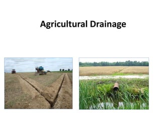
  • 2. Agricultural drainage • Agricultural drainage comprises of removal of excess surface and ground water from agricultural lands. • Excess water or concentration of salts in the root zone or at the land surface do not permit the plant roots to function properly, resulting in poor growth and yield of the plants. In extreme cases of water logging and salt problems, the seeds may not germinate; or in case of standing crops, they may wilt permanently. The excess soil moisture (waterlogging conditions) affects crop growth mainly because of deficient aeration. • Most crops will grow and respire normally if the oxygen diffusion rates exceed 4 x 10⁻⁷ g/cm2/min. • Growth rate of most plants reduces when the soil water solution has a salt concentration exceeding about 5000 ppm.
  • 3. Causes of water logging: • Waterlogging is caused both by natural and man-made (artificial) conditions. The natural causes are, • Poor natural drainage of the subsoil (hard pan) • Submergence under floods • Deep percolation from rainfall The artificial causes consists of • High intensity of irrigated agriculture • Heavy seepage losses from unlined canals, and farm water courses • Enclosing irrigated fields with embankments and choking up natural drainage • Hydraulic pressures from upper saturated areas at higher elevations • Non maintenance of natural drainages or blocking of natural drainage channels by roads, railways etc.
  • 4. • Ministry of Water Resources Govt. of India(1991) adopted the following norms for identification of waterlogged areas: (i) Water logged area : Water table within 2 m from land surface (ii) Potential area for water logging : Water table between 2 – 3 m from land surface (iii) Safe area : Water table below 3 m from land surface
  • 5. Factors influencing drainage: The factors affecting drainage are, I. Topography of the affected area and the adjoining watershed which contribute flow into the problem area II. Soil characteristics III. Rainfall and other climatic factors IV. Crop factors • Topography factors: Topography is of prime importance in drainage, influencing the general plan and location of the outlets, field drains, link drains and main drains. Favourable topography may provide adequate surface drainage and reduce the need for artificial subsurface drainage. • Drainage properties of soil: A soil may need artificial drainage for either or both of the following reason – Where there is a high water table that should be lowered - Where excess surface water cannot move downward through the soil or over the surface of the soil fast enough to prevent the plant roots form suffocating. (i) Rainfall: Rainfall causes runoff on land and thereafter to the drainage channels with some infiltration in to the sol. This water must be carried away from agricultural lands within a short period so that it does not create harmful conditions of water logging. As per United States Bureau of Reclamation, surface drains should be designed to handle flows from 5-15 year storm frequencies. Relatively expensive structures like cross structures for major highways, railway embankments and canals should be designed for flows from a 25 year storm. For less important crossings, flows from a 10 year storm can be used; and flows from a 5 year storm can be used for structures within a field or a farm. (ii) Crop factors: Most crops, when submerged over 48 hours, suffer reduced production, and some are destroyed completely.
  • 6. Drainage coefficient: • The rate of drainage is a key factor in establishing the needed capacity of a drainage system. The rate, expressed as the depth in centimeters of water drained off from a given area in 24 hours is called the drainage coefficient or drainage design rate. It is the design value at which water is to be removed from a drainage area. It may also be expressed in terms of flow rate per unit of area, as cubic metres per square kilometer per 24 hours or in terms of the flow rate per unit of area which varies with the size of the area. • For average small drainage projects the drainage coefficient would range from 6 to 25 mm. • Rainfall is the most important factor influencing the value of the drainage coefficient in places where drainage is needed to remove rainfall-runoff.
  • 7. Problem1: A drainage canal discharges 0.2 cubic metres of water per second and drains 250 hectares. What is the drainage coefficient of this land? Solu: • Total water discharged in 24 hrs = 0.2 x 60 x 60x24 = 17280 cubic metres • Drainage coefficient (depth of water drained in 24 hrs) = 17280/(250 x 10000) = 0.0069 m = 0.69 cm or say 7 mm Problem 2: The drainage coefficient of a land is 10 mm. calculate the capacity required at the outlet end of the drainage ditch draining a watershed of 300 hectares. Solu: • Total quantity of water to be drained in 24 hrs = (10 x 300 x 10,000) / 1000 = 30,000 cu.m • Discharge rate (capacity) = 30,000/(60x60x24) = 0.347 cu.m per sec
  • 8. Darcy’s Law The law of flow of water through the soil was first studied by Darcy (1856) In a saturated soil for laminar flow conditions, the rate of flow (or discharge per unit time) is proportional to the hydraulic gradient. q = k i A Where q – discharge per unit time (Q/t) A – total cross sectional area of soil mass i – hydraulic gradient k – Darcy’s coefficient of permeability v – velocity of flow or average discharge velocity • If a soil sample of length L and cross sectional area A, is subjected to differential head of water, h1 – h2, the hydraulic gradient I will be equal to (h1-h2)/L and we have • When the hydraulic gradient is unity, k is equal to v. A L h h k q 2 1  
  • 9. Methods of drainage • A drainage system is selected after careful examination of the various alternative methods. The first requirement is a reconnaissance survey to determine the general feasibility of draining the land, kind of system needed and approximate cost. Method of drainage: The following are the principal methods of drainage: 1. Surface drainage, mainly through a network of open channels and including land grading and smoothing 2. Subsurface drainage or pipe drainage and 3. Vertical drainage through tube wells.
  • 11. Surface drainage: • Surface drainage is the removal of water from the surface of the land. The water may be from excess rainfall, over-irrigation, losses from conveyance channels and storage systems, or seepage from area at higher elevations. Flat or level land having impermeable sub soils with shallow top soil frequently requires surface drainage because pipe drains are not practical or economical. Surface drainage can be considered in three functional parts, viz., 1) collection system, 2) Conveyance or disposal system and 3) Outlet. • Water from the individual fields is collected through collection system and moves through the disposal system to the outlet. • In irrigated areas, the collection system consists of the field drains and the conveyance system consists of the intermediate and main drains
  • 12. Drainage systems for flat area: There are four types of drainage systems used in flat areas (less than 2 percent slope), these are, 1. Random drain system 2. Parallel field drain system 3. Parallel open ditch system 4. Bedding system
  • 13. Random drain system: • The random drain system is used where small scattered depressions to be drained occur over the area. Where possible drains are designed to connect one depression to another and water is conveyed to an outlet. The drains connecting the depressions could be surface drains or underground pipelines or subsurface drains.
  • 14. Parallel field drain system: • It is most effective method of surface drainage and is well suited both for irrigated and rainfed areas. In this system, individual fields are properly graded such that they discharge into field drains. The field drains may discharge into field laterals bordering the fields and the laterals in turn lead to the mains. Laterals and mains should be deeper than field ditches to provide free outfall. This is also referred to as the field ditch system.
  • 15. Parallel open ditch system: • The parallel open ditch system is applicable in soils that require both surface and subsurface drainage. It is similar to the parallel field drain system, except that in this system the drains are replaced by open ditches which are comparatively deeper and have steeper side slopes than the field drains. The spacing of the ditches may vary from 60 to 200 m. this system is also known as diversion ditch system. Bedding system: • The bedding system for surface drainage is essentially a land forming process. The land is ploughed into beds, separated by dead furrows which run in the direction of prevailing slope. Ploughing is done parallel to the furrow. All the farming operations can be done either across the beds or parallel to the furrow. Bedding was proved to be successful on poorly drained soils and on flat lands and on slopes up to 1.5 percent. • For hydraulic conductivity k = 0.5 cm/day the bed width vary from 8 to 12 m. The length of bed vary from 100 to 300m.
  • 16. Design of open drains: Open drains are classified as 1. Field drains (which remove surface water directly from fields) 2. Outlet drains (Which provide outlets for tile drains and tributary channels) The open ditch drainage system consists of a network of channels draining a given watershed. The design of drainage canals or channels are similar to the design of open channels. In contrast to the irrigation channel, the capacity of a drainage channel should increase downstream. Design: Open channel or Open ditch is defined as any conduit in which water flows with a free surface. T = Top width t = Width of water surface when the water is at depth d D = depth of channel after free board is added d =depth of flow in channel b = bottom width of channel a,c = wetted sides of channel = the angle between the inclined side and the horizontal 
  • 17. Wetted perimeter: The wetted perimeter p is the surface which is in contact with water P = a+b+c The larger the wetted perimeter (p) is for the same area of cross section (a) of the stream, the less the velocity (v) of the stream tends to be and vice-versa. Velocity v is directly proportional to and is inversely proportional to Hydraulic radius: Hydraulic radius or the hydraulic mean depth, is ratio between the cross sectional area (a) of the stream and its wetted perimeter (p). The hydraulic radius (R), computed from the formula R=a/p, is an important parameter in determining the velocity of water flowing in channels. The velocity of flow in channel is directly proportional to the square root of the hydraulic radius Hydraulic slope: Hydraulic slope (S) of a channel is expressed as the ratio h/L where h is the vertical drop for a length ‘l’ of the stream. Velocity of flow in a channel varies directly as the hydraulic slope (i.e Freeboard: Freeboard is the vertical distance between the highest water level anticipated in the design and the top of the retaining banks. It is provided to prevent overtopping of structures because of wave action or the development of unforeseen conditions. a p R v  S v 
  • 18. Angle of repose: The maximum slope or angle at which a material such as soil remains stable is called is called the angle of repose. When the slope exceeds the angle of repose, mass movement by slippage as well as by water erosion could be expected. Velocity: In which, C= is a constant depending on the size, character of slope The determination of the value of C in Chezy’s formula is comparatively difficult. In which v= velocity, metres per second R = hydraulic radius, metres S = hydraulic slope (h/l) n = roughness coefficient of the channel lining n S R v 2 1 3 2  S R v  RS v 
  • 19. Capacity of channel Q = a.v Q = capacity of channel The cypress creek formula: This formula in English units is given by; Where Q =design discharge (cuft per second) C = coefficient depending upon the degree of protection p = coefficient (general value 5.6) A = area in sq.miles The Boston society formula The surface drain design given by Boston Society of Civil Engineers’ is Where, Q = is the peak discharge in cusecs C = is coefficient A = is the peak catchment area in sq.miles. In order to economise the construction of drainage system, sometimes the drains are designed for a discharge varying from ¼ to 1/12 of the calculated peak discharge. P CA Q  2 1 CA Q 
  • 20. Sub-surface Drainage Subsurface drainage: • Subsurface drainage refers to the removal of excess water present below the ground surface. • A subsurface drainage system is required for water table control and for maintaining a favourable salt balance in the crop root zone. • Subsurface drainage systems may comprise of buried horizontal pipelines, deep open channels (ditches), or a system of drainage wells. • Deep open drains serve the purpose of removal of excess surface water and lower the ground water table. However, their main functions are removal of excess surface water and to serve as outlets for underground pipe drains usually called tile drains. • Subsurface drainage may be obtained mainly by horizontal subsurface drainage systems called tile drainage and vertical subsurface drainage systems comprising of a system of drainage wells.
  • 21.
  • 22.
  • 25. Benefits of subsurface drainage: • Aeration of rootzone for maximum development of the plant roots • Opportunity for desirable soil micro organisms to develop through aeration and higher soil temperatures • Availability of the soil for early cultivation • Improvement of soil moisture conditions for machinery operation • Removal of undesirable salts from the root zone
  • 26. Investigations for subsurface drainage: For the design and installation of subsurface drainage system the following information will be needed: 1. Topographic map of the area 2. Data on soil salinity and alkalinity, drainable porosity etc. 3. Position and fluctuations of water table levels relative to the ground surface and artesian pressures 4. Groundwater quality 5. Logs of soil and subsoil materials 6. Hydraulic conductivity measurements 7. Crops proposed to be grown and their drainage requirements 8. Irrigation practices and requirements.
  • 27. • A topographic map of the area is needed both for planning the surface and subsurface drainage systems. The topographic map gives the details of land slope, possible outlets, existing drainage pattern, undulating land area etc., and serves as the base map for preparing the watertable contour maps. • Information on soil salinity and alkalinity is needed if surface drainage systems are to be planned along with reclamation of such soils. • The groundwater conditions are observed by installing piezometers and observation wells. The piezometers or observation wells are small diameter pipes (2.5 to 5 cm) installed vertically into the ground. The piezometer indicates the hydrostatic pressure of groundwater at the specific point in the soil where the lower end of the tube is located. In case of observation wells, the water enters into the well through the entire section of the pipe located below the watertable. • The observation wells are useful for determining the depth of water table from ground level. In areas where subsurface drainage systems are planned, observation wells could be located in a grid pattern. From the data obtained from observation wells, water table contour maps and watertable isobaths maps can be plotted. • Watertable contour maps: it show the configuration of the watertable surface in the same way as the contour map of an area show the configuration of the land surface. The water table contour maps are useful in determining the direction of groundwater flow the location and extent of the high watertable areas. • From the observation well data, one can prepare a map what is known as a water table isobaths maps. Isobaths lines are lines of equal depth to water table. They are prepared in the same manner as water table contour maps. Isobaths maps indicate at a glance the area affected by high water table problems. In areas provide with subsurface drainage, the isobaths maps indicate the effectiveness of the drainage system in different parts of the area.
  • 28. Tile drain system The design of a tile drain system consists in determining (1) Layout of the system(2) depth and spacing of the drains (3) size of the drains (4) material of the tiles (5) grade of the tile lines (6) envelope materials and accessory structures and (7) outlets Layout of Tile Drainage Systems: The different types of tile drainage layout are 1. Random or natural 2. Herringbone 3. Grid iron 4. The interceptor drain • Random or the natural system is used for draining insolated patches when the entire area does not need drainage. It is thus economical. Tile lines are laid more or less at random to drain these wet areas. • The herringbone system is used in areas where a main line or submain could be laid in the low area and laterals could be drawn from both sides. This system is used where the main or submain lies in a narrow depression. • The grid iron system is similar to herring bone system except that the laterals enter the main only form one side. The system could be more economical than the herringbone system as less number of junctions are used. • The interceptor or the cut-off drain is placed at the upper edge of a wet area to intercept the subsurface seepage. Open drains also used for the purpose but require considerable land area. The interceptor drain should be laid along the bottom of the permeable layer in order to intercept the seepage causing the damage.
  • 29.
  • 30. Depth and spacing • The depth and spacing of the tile drains are closely interrelated and depend upon the hydraulic conductivity of the soil, kind of crops, extent of surface drainage, outlet conditions and the agronomic practices followed. • The depth of the tile drains should be such that midway between the drains the watertable should be at a satisfactory depth. • If the tiles are located below the impermeable layer, backfilling of the trenches should be done with permeable soil.
  • 31. Interceptor drainage and relief drainage: • Subsurface and open drains may be either of the interceptor type or relief type. If the system intercepts the water coming from other areas and diverts it suitably to save a certain part of the area from getting waterlogged then it is interceptor drainage • When the drainage system in a waterlogged area removes the excess water and gives relief to the land, it is relief drainage.
  • 32.
  • 33.
  • 34.
  • 35. Hooghoudt’s equation This equation gives the relation between the spacing of drains and the height of the watertable built up between the drains due to a constant rate of irrigation or rainfall. The analysis applies to open drains or subsurface drains. Fig. shows a physical situation considered. In deriving this equation, the following assumptions are made: The soil is homogeneous Darcy’s law is valid for the flow The hydraulic gradient at any point is equal to the slope of the watertable above that point (i=dy/dx) and the water flows horizontally. The last set of assumptions are known as the Dupuit-Forchheimer (D-F) assumptions.
  • 36.
  • 37.
  • 38. Design of subsurface drainage – tube diameter, perforation, outlet • Horizontal subsurface drainage systems comprised of a network of buried pipes as lateral drains, connected to buried collector drains leading to open ditches serving as outlet drains. Tube diameter: • The laterals may be made of burnt clay tiles (plain or perforated) or cement concrete tiles. Clay or concrete tiles are 10 to 15 cm in diameter. They are of short lengths of 30,65, or 60 cm. PVC pipes made in continuous length of 200 to 250 m. Capacity of tile drains: • The hydraulic capacity of tile drains is determined from the Manning’s velocity equation. A minimum velocity of flow of 0.4 m/sec will keep the line flushed clear of silt. Roughness coefficient n • .The design value of n usually adopted are 0.013 for clay and concrete pipes and 0.015 to 0.02 for corrugated plastic tubing Perforations in drain pipe: • As the number of holes is increased the relative increase in flow decreases, particularly if there are more than 65 holes per metre. The effect of perforations in reducing the flow is less at great depths than it is when closer to the surface. The use of envelope materials around the perforated pipe would reduce the number of perforations in order to get the desired flow.
  • 39. Materials for tiles: • Concrete, burnt clay and PVC are the materials used for tiles. Concrete 1:2:4 proportions should be used and the tiles should be properly cured. • Clay tiles should be well burnt and without any defects. Good clay tiles have a distinct ring when lapped with a metal object. Clay tiles can be used in acid and alkaline soils • Plastic pipes are popular for tile drainage. The common materials are polyvinyl chloride (PVC) and polythelene. Corrugated plastic pipes have greater hydraulic resistance than smooth pipes and hence a larger sized pipes are needed to drain the same amount of water.
  • 40. Loads on drain pipes: Drain pipes have to bear the load of the soil above them. Drains located at shallow depths (less than 1 m) are subjected to both the soil weight and any other load resulting due to machinery. Drains located at deeper depths are subjected to soil loads only. For estimating the loads on drain tiles two formulae are used 1. Ditch conduit formula for narrow trenches 2. The Projecting conduit formula for wide trenches If the ditch is more than 2 to 3 times the outer diameter of the tile then it is considered as a wide trench. The ditch conduit formula Where Wc = load on pipe Cd = load coefficient W = unit weight of fill material Bd = width of trench at the top of the pipe The projecting conduit formula for wide ditch: Where Cc= load coefficient for project conduits Bc= outside diameter of the conduit The load coefficient Cd and Cc in the formulae are functions of the frictional coefficients of the soil. 2 d d c WB C W  2 c c c WB C W 
  • 41. Accessories for tile drain systems (i) Envelope materials/ Filters for tile drainage system: • Filter materials or envelope materials are placed around the tiles. The envelope materials prevent the entry of the relatively coarser particles into the tiles. The envelope material act as bedding material and thus allow the tiles to take greater loads. They also increase the effective diameter of the tiles and allow quantities of water to flow into the tiles. • Envelope materials: it consists of gravel, coarse sand, organic materials like corn cobs, straw, coir matting. Gravel has been used widely because of its efficiency. • The united states Bureau of Reclamation recommends the following criteria for the design of gravel envelopes For uniform soils For graded soils 10 to 5 soil of D envelope of D 50 50  58 to 12 soil of D envelope of D 50 50 
  • 42.
  • 43.
  • 44. (ii) manholes and sedimentation basins: These are vertical structures installed at regular intervals along the tile lines to help in inspection of the tile lines and cleaning the accumulated sediment. These are constructed using either concrete or brick masonry and are of dimensions enough for a person to enter. These could be installed at junctions of tile lines. The top of the manholes or sedimentation basin can be kept at ground level or below ground level.
  • 45. (iii)Intlet to Tile Drain: Inlets to tile drains are used to admit surface runoff into the tile lines. There could also be used for flushing the tile lines. The two types of inlets used are the 1. Blind inlet (also called French drains) 2. Surface inlets Blind inlets are cheaper and do not interfere with farming operations but they are likely to get clogged. Surface inlets have provision for preventing the trash and other suspended materials entering the tile drains.
  • 46. Mole drainage: Mole drainage is a semi-permanent method of subsurface drainage. It is similar to tile drainage in layout and operation. Instead of the permanent tiles, a continuous circular channel is created in the soil below the ground level using a mole plough with mole plug. Mole drains are unlined circular or oval underground earthen channels, formed within highly cohesive or fibrous soils by a mole plough. The mole plough has a long blade-like shank to which is attached a cylindrical bullet nosed plug known as a mole. The mole plough is drawn by a high powered prime mover. As the plough is drawn through the soil, the mole forms cavity at a set depth. The fractures formed by the coulter and mole provide escape routes for water through the soil, and into the mole channel. The channel receives, conducts and discharges the water to the drainage ditches at the edge of the field. • Mole channels usually range in diameter from 7.5 to 10 cm • Spacing ranges from 1.5 to 9 m • Depth of channel varies from 50 to 75 cm • Mole drains are formed about 40 to 60 cm below the soil surface. • Two forms of soil failure occurs when a tine is pulled through a cohesive soil. At shallow depths the soil is displaced forwards, sideways and upwards. Failure occurs in shear along well defined rupture planes which radiate from the top of the time (of the mole plough) towards the land surface at an angle of about 45⁰ to the horizontal.
  • 47.
  • 48.
  • 49.
  • 50. Drainage wells/ Vertical drainage: Drainage by wells is a form of subsurface drainage. It is also referred to as vertical drainage. It is feasible only under certain following conditions: • Aquifer conditions: the area to be drained should be underlain by an aquifer, pumping from which lower down the watertable. • Water quality: the underground water should be of satisfactory quality. Thus the pumped water could be used for irrigation • Soil condition: the hydraulic conductivity of the soil layers to be drained is important as these soil layers should allow free percolation water. Drainage wells are most successful in irrigated area when the pumped water could be used for irrigation.
  • 51. Leaching Requirement (LR) Leaching Requirement (LR) is defined to be the amount of water applied to flush out of the root zone excess salts that are present in the soil and which are detrimental to crop production. Different crop types and different varieties of the same crop can differ in tolerance to salinity. The minimum amount of water required to remove salts from the root zone area is estimated using the ratio of the electrical conductivities of irrigation water (applied water) and drainage water Where ECiw is the electrical conductivity of irrigation water (dS/m) ECdw is the electrical conductivity of drainage water (dS/m). Any amount of water in excess of the leaching requirement that goes to deep percolation is non-beneficial, and reduces water use efficiency at that scale. It should be noted, however, that due to uncertainties in quantifying leaching requirements, and due to low distribution uniformities of applications, some amount of water in excess of leaching requirement may be reasonable. dw iw EC EC LR 
  • 52. • Drainage water can be used directly for irrigation purposes without severe crop yield reductions where the salinity of the drainage water does not exceed the threshold salinity value for the crops grown and good drainage conditions exist. As crops are often more sensitive to salinity during the initial growth stages, research in India has revealed the importance of pre-irrigation with good quality irrigation water. Higher crop yields were attained when freshwater pre-irrigation was applied with only drainage water being applied thereafter. Under these conditions, drainage water with salinity levels exceeding the threshold value could be used whilst maintaining acceptable crop yields.
  • 54.
  • 55.
  • 56. Water in Soil After Heavy Rain
  • 57.
  • 58.
  • 59.
  • 60.
  • 61. Aerial view of tile drainage system
  • 63. A tile plugged with roots
  • 64.
  • 65.
  • 66. A tile plugged with roots Mole drainer showing blade, torpedo foot and plug Cross section of mole plough effect in soil. Mole drainage
  • 67. Lecture 32 Random drainage - herringbone - grid iron types
  • 68.
  • 69.
  • 70.
  • 71.
  • 72.
  • 73. Lecture 33 Pipe materials - tile, plastics cement - Envelope materials. Load factors - blind inlet - filters - mole drains, drainage wells
  • 74.
  • 75.
  • 76.
  • 77.
  • 78.
  • 79. Pipe materials satisfy the following conditions: 1.The pipe materials should withstand various pressure and stresses like tensile, Compression and hoop under water hammer condition. 2.It should be resistant to corrosion and abrasion caused by the water. 3.It should be durable having sufficient strength to bear the external loads coming over it. 4.It should be structurally safe. 5.It should have minimum possible weight. 6.It should be economical and uniform in size and shape. 7.It should be capable of easy hoisting and handling at site.
  • 80. CONSTRUCTIONS 1. Pipe inlet laid below the ground surface. 2. Tile line section placed over the inlet 3. Coarse materials are filled on the inlets. 4. Size of the materials is become less towards the surface 5. Finally back filling with sand.
  • 81. LOAD FACTOR The load factor is the ratio of the strength of a rigid conduit under given bedding conditions to its strength as determined by three edge bearing test. Generally it ranges from 1.2 to 1.5 for drainage pipe laying conditions.
  • 82. DRAINAGE WELL The use of wells for the purpose of draining land is called drainage well. The soil permeability plays an important role in determining the feasibility of well drainage.