Download to read offline
![International Research Journal of Engineering and Technology (IRJET) e-ISSN: 2395-0056
Volume: 05 Issue: 06 | June-2018 www.irjet.net p-ISSN: 2395-0072
© 2018, IRJET | Impact Factor value: 6.171 | ISO 9001:2008 Certified Journal | Page 486
Miniaturized Wide Bandwidth MIMO Dielectric Resonator Antenna
using Defective Ground Structure for UWB Applications
A Keerthanai Priya1, B. Bhuvaneswari2
1PG Student, Department of Electronics and Communication Engineering, Panimalar Engineering, College,
Chennai, India
2Professor, Department of Electronics and Communication Engineering, Panimalar Engineering, College, Chennai,
India
---------------------------------------------------------------------***---------------------------------------------------------------------
Abstract -The current scenario of wireless communication
needs compact and wide bandwidth radiators for effective
communication. MicrostripPatchAntennasareusedwidely, as
they are low-profile. The efficiency of microstrip antennas is
poor because of conductor loss and spurious radiation. To
overcome these problems, MIMODielectricResonatorAntenna
(DRA) with Defective Ground Structure (DGS) is proposed in
this paper work. The two element MIMO DRA is made up of
Rogers RO4350 with dielectric constant and thickness as 3.5
and 0.76mm respectively and designed at 6.9 GHz. Bandwidth
can be enhanced by placing DGS. A stub is placed between two
DRA to provide the isolation between the two antennas. The
Ultra Wide Band obtained here is 4.692 GHz (5.92-10.62) GHz
at a resonant frequency of 6.9 GHz with reflection coefficient
of -43 dB without interfering with WLAN frequencies. Three
types of design trials were done. The design is carried out in
the fact that dielectric material with low dielectric constant
will provide more bandwidth. The overall dimension of the
compact antenna is about (29×29×2.295) mm3. The various
parameters like reflection coefficient (S11 dB), VSWR,
directivity, gain are analyzed.
Key words: DGS (Defected Ground Structure), DRA, MIMO
elements, WLAN, Reflection coefficient (S11) dB
1. INTRODUCTION
In current scenario applications, we need compact planar
antennas for wireless communications. To accomplish this,
microstrip patch antennas of various shapes has been
proposed. The major demerit of patchantennasarespurious
radiation due to presence of conducting element acting as
antenna and it provides only narrow bandwidth [1] and
hence it is not suitable for high frequency millimetre wave
applications.
To overcome the demerits mentioned above, Dielectric
Resonator Antenna (DRA) is proposed. Long ago dielectric
materials were used only as resonators, but now it isusedas
radiators too [2]. To make DRA to radiate the following
constraints has to be considered such as type of dielectric
material used, dielectric constant, temperaturecoefficient,Q
factor, mode of excitation to make it to work at particular
frequency [3].
A huge amount of research work has been carried out in
DRA of various shapes. Rectangular DRA provides more
flexibility towards design [4].Rectangular WaveguideModel
is used to design and analyze DRA in rectangular shape [5].
Cross polarization level is lower in rectangular DRA. MIMO
(Multiple Input Multiple Output) provides more gain when
compared to single antenna. In [6], compactness and entire
Ultra Wide Band is achieved for the size (29×29×5) mm3.
WLAN band is suppressed using L shaped parasitic stripes.
Defective Ground Structures (DGS) is placed in ground plane to
improve the bandwidth [7 & 8]. In [9], Z shaped DGS is placed
to enhance the bandwidth with frequency range (8 - 12) GHz.
Compactness is achieved using meandered structure in the
ground plane [10]. Good isolation is achieved by placing DGS in
case of MIMO antennas which in turn reduces mutual coupling
between the antennas [11]. In [12], a four element MIMO
antenna was presented each element has individual ground plane
to reduce mutual coupling between the antennas. In [13], by
placing the antennas orthogonallyand introducing a narrowslit in
the ground plane improves the isolation between the antennas.
Dielectric material with lower dielectric constant will provide
more bandwidth [14].
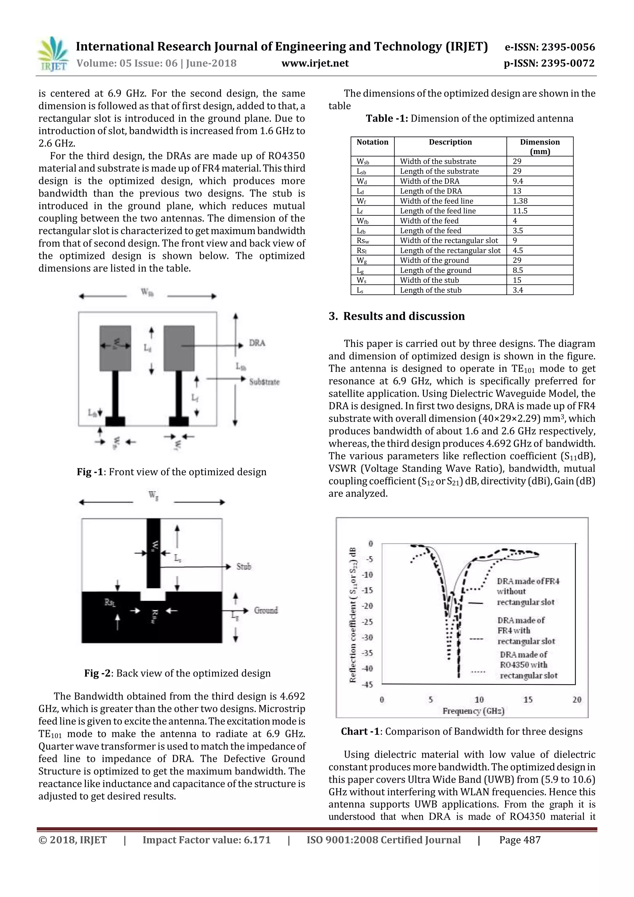
2. DESIGN OF ANTENNA
Dielectric Resonator Antenna (DRA) is designed using
Dielectric Waveguide Model. The design is simple for
rectangular DRA and provides moredegreesoffreedom.The
feeding technique used here is microstrip line method. The
antenna consists of three layers they are ground, substrate
and third layer act as DRA. The ground is normal Perfect
Electric Conductor (PEC) withthickness0.035mm,substrate
can be RO4350 or FR4 (design were carried out using both
substrates individually)withthickness0.76mmand1.57mm
respectively.
The antenna is analyzed with DRA made of RO4350 and
DRA made of FR4 for three possible designs. Forall thethree
designs, the ground is made defective to enhance the
bandwidth. For the first design, the DRA is made up of FR4
material with dielectric constant 4.4 and thickness 1.57mm
and substrate is RO4350. The overall dimension of the
antenna is (40×29×2.29) mm3. A stub is placed between the
two DRAs which produces isolation and reduces mutual
coupling between the two antennas. The ground is defected
and hence the bandwidth of about 1.6 GHz is obtained which](https://image.slidesharecdn.com/irjet-v5i6100-180726103938/75/IRJET-Miniaturized-Wide-Bandwidth-MIMO-Dielectric-Resonator-Antenna-using-Defective-Ground-Structure-for-UWB-Applications-1-2048.jpg)
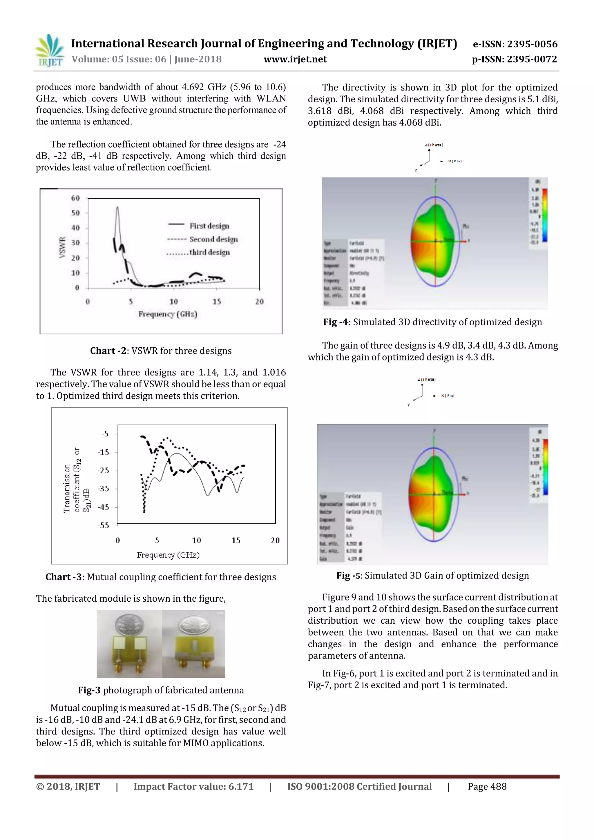
![International Research Journal of Engineering and Technology (IRJET) e-ISSN: 2395-0056
Volume: 05 Issue: 06 | June-2018 www.irjet.net p-ISSN: 2395-0072
© 2018, IRJET | Impact Factor value: 6.171 | ISO 9001:2008 Certified Journal | Page 489
Fig-6: Surface current at port 1
Fig-7: Surface current at port 2
Table-2 Comparison of various parameters of all the three
desgns
Design Size
in
(mm3)
(S11 or
S22) dB
@ 6.9
GHZ
(S12 or
S21) dB
@ 6.9
GHZ
VSWR
@ 6.9
GHz
Directivi
ty
(dBi)
Gain
(dB)
Band
Width
(GHz)
Design 1 40×29
×2.3
-24 -16 1.1 5.1 4.9 1.6
Design 2 40×29
×2.3
-22 -10 1.3 3.61 3.41 2.6
Design 3 29×29
×2.3
-41 -24.1 1.016 4.08 4.3 4.692
The size of optimized design is less when compared to other
two designs hence compactness is also achieved.
4. CONCLUSIONS
In this project, a new compact dielectric resonator
antenna is proposed, simulate and fabricated. The overall
compact dimension is (2929×2.295) mm3 and a wide
bandwidth is obtained for about 4.3 GHz. Since, the dielectric
resonatorantennasdoesnotcontainanyconductingmaterial,
it does not provide any conduction loss, spurious radiation
and it is verysuitable forhighfrequencyapplicationsandloss
is also less. The design of the antenna is carried out with the
fact that material with low dielectric constant will provide
more bandwidth. This antenna produces very wide band
response and hence supports UWB applications.
The extension of this work can be done by, increasing the
bandwidth for higher millimeter wave frequencies and
thereforeitsupportsfor5Gapplications.DielectricResonator
Antenna is one of the antennas which well supports for high
frequency future applications.
6. REFERENCES
[1] J.R. James, and P.S. Hall, ’Handbook of Microstrip
Antennas’, vol. 1. IEEE, Peter Peregrinus Ltd:Clarendon,
1989, pp. 1–17.
[2] Professor J. R. James, ‘A Handbook on Dielectric
Resonator Antennas’, research studies press ltd.
Baldock, Hertfordshire, England, 2003.
[3] Aldo Petosa, ‘Dielectric Resonator Antennas: A
Historical Review and the Current State of the Art’, IEEE
Antennas & Propagation Magazine,vol.52,No.5,October
2010.
[4] Rajesh Kumar Mongia, ‘Theoretical and Experimental
Investigations on Rectangular Dielectric Resonator
Antennas’, IEEE transactions on antennas and
propagation, vol. 45, no. 9, September 1997.
[5] Mridula.S, ‘Investigation on a microstrip excited
Rectangular Dielectric Resonator Antenna’, cochin
university of science and technology, 2005.
[6] Mohammad Abedian,’ Compact ultra wide band MIMO
dielectric resonator antennas with WLAN band
rejection’, IET, Microwaves, Antenna and Propagation,
vol.11 iss.11, pp. 1524-1529, 2017.
[7] P. Sari, ‘Defected ground structure for bandwidth
improvement of artificial magnetic conductor-based
microwave absorber’, International Conference on
Telecommunication Systems, Services,andApplications
(TSSA), vol.1, no. 3, oct.2012, pp. 200–203.
[8] Nader Komjani, ‘Bandwidth Enhancement of microstrip
Patch antenna using Jerusalem cross-shaped frequency
selective surfaces by invasive weed optimization
approach’, progress in Electromagnetic Research,
January 2011.
[9] Shalini Sah, ‘Defective Ground Surface and frequency
selective surface based dual band Microstrip Antenna’,
Second International Conference on Computational
Intelligence and Communication Technology, October
2016.
[10] Zhang, S., Ying, Z., Xiong, J., et al.: ‘Ultra wide band
MIMO/diversity antennas with a tree-like structure to
enhance wideband isolation’, IEEE Antenna Wirel.
Propag. Lett., 2009, 8, pp. 1279–1282
[11] Liu, X.L., Wang, Z.D., Yin, Y.Z., et al.: ‘A compact ultra
wide band MIMO antenna using QSCA forhighisolation’,
IEEE Antenna Wireless and Propagation. Letter.
[12] Tang, T.-C., Lin, K.-H.: ‘An ultrawideband MIMO antenna
with dual bandnotched function’, IEEE Antenna Wirel.
Propag. Lett., 2014, 13, pp. 1076–1079
[13] Gourab Das, Anand Sharma, Ravikumar Gangwar,
‘Dielectric Resonator based two element MIMOantenna
system with dual band characteristics’, IET Microwave
Antenna and propagation, volume .issue. 5, 2018.
[14] Gabriel Banciu, ‘The influence of the dielectric constant
in DRA’,978-1-4673-8197-0/16/$31.00 ©2016 IEEE.](https://image.slidesharecdn.com/irjet-v5i6100-180726103938/75/IRJET-Miniaturized-Wide-Bandwidth-MIMO-Dielectric-Resonator-Antenna-using-Defective-Ground-Structure-for-UWB-Applications-4-2048.jpg)

This document presents a miniaturized wide bandwidth multiple-input multiple-output (MIMO) dielectric resonator antenna (DRA) using a defective ground structure for ultra-wideband applications. The antenna is designed to operate at 6.9 GHz and achieves an ultra-wide bandwidth of 4.692 GHz from 5.92 to 10.62 GHz without interfering with wireless local area network frequencies. Three designs are analyzed and the optimized design uses two DRAs made of Rogers RO4350 substrate with a dimension of 29x29x2.295 mm3. A stub is placed between the DRAs to provide isolation and reduce mutual coupling. The defective ground structure enhances the bandwidth. Simulation results show the optimized design meets requirements


