IRJET- Automatic Hand Brake System
•
1 like•75 views

https://www.irjet.net/archives/V5/i3/IRJET-V5I3796.pdf

Recommended
Recommended
More Related Content
What's hot
What's hot (11)
Similar to IRJET- Automatic Hand Brake System
Similar to IRJET- Automatic Hand Brake System (20)
More from IRJET Journal
More from IRJET Journal (20)
Recently uploaded
Recently uploaded (20)
IRJET- Automatic Hand Brake System
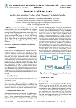
- 1. International Research Journal of Engineering and Technology (IRJET) e-ISSN: 2395-0056 Volume: 05 Issue: 03 | Mar-2018 www.irjet.net p-ISSN: 2395-0072 © 2018, IRJET | Impact Factor value: 6.171 | ISO 9001:2008 Certified Journal | Page 3377 Automatic Hand Brake System Akash D. Singh 1, Siddhesh P. Rahate2, Amit V. Pawaskar3, Ravindra K. Ambekar4 1Student of Diploma Mechanical Engineering, Rajendra Mane Polytechnic 2 Student of Diploma Mechanical Engineering, Rajendra Mane Polytechnic 3,4Professor, Department of Mechanical Engineering, Rajendra Mane Polytechnic, Ambav-415 804, Maharashtra, India ---------------------------------------------------------------------***--------------------------------------------------------------------- Abstract - As we know human life are gets more busy and complicated due to their work and development. So in today’s advance technology maximum inventions or research is done to reduce human effort and for providing comfortable life to them. We know in today’s vehicles a normal steering system is replace by power steering system for reducing some human effort and providing comfortable ride as compare to normal system. In this paper we are discuss how to reduce a human effort which is required to apply the hand brake whileparking of vehicle. Key Words: Hand brake, Hydraulic system, Solenoid 1. INTRODUCTION In road vehicle s the parking brake also called as handbrake, emergency brake or e-brake is used to keep the vehicle stationary. In normal vehicles a hand brake is consist of a cable connected to two wheel brakes at one end and the other end to a pulling mechanism which is operated by human with hands. In this case human effort is required to pull the mechanism and apply the brakes. To minimize this human effort is the main aim of our project with help of hydraulic system .In some cases people are forget to apply hand brakes while parking the vehicle which results in moving the vehicle and causes accidents. To avoid this we develop such system in which hand brakes are control with ignition system of vehicle. Means a hand brake mechanism and ignition system of vehicle is connected each other with simple hydraulic system for applying the hand brake while parking. 1.1 Normal Hand brake When we lower the lever the brake cable will become loose and brake is released. When we need to apply the hand brake while parking a vehicle we pull the hand brake lever upward side, duetothis the hand brake cable is pulled which causes expansion of brake shoe in brake drum of wheel. And hand brake isapply. 1.2 Automatic Hand Brake System Now we have become more interested to see how automatic hand brake system is actually works. First of all this system consist a simple hydraulic system with simple circuit. This hydraulic system plays very important role forapplyingand releasing hand brake while parking car. This hydraulic circuit consist of hydraulic pump, 4x2 solenoid operated direction control valve, pressure relief valve , single acting actuator, oil reservoir, hosesand fittingsetc. The handbrake cable is attached to the end of actuator rod. When power supply is made on means ignition of vehicle is on it will rotates the motor and then hydraulic pump. The pump suck the oil from reservoir and pressurized it at certain pressure. The pressurized oil enters in single acting actuator through solenoid operated direction control valve and oil pushesthe piston of actuator in forward , hand brake cable become loose and brake will be release. When ignition key is off it will stops the pump and direction control valve changes its position simultaneously, due to this oil returns to tank from actuator. Which causes backward movement of actuator piston, the brake cable will get pull and thus hand brake get applied immediately. I t means the application of handbrake is done automatically with help of vehicle ignition system. Fig. 1: Simple block diagram of Automatic hand braking system 2. COMPONENTS USED 2.1 Gear Pump Hydraulic pump is used to supply pressurized oil through overall circuit for working. We used gear pump of having discharge 3.4 LPM. Pump having two meshing gears inside the casing . One gear is rotated by motor and due to meshing another gear is also starts to rotate. Pump having two ports one is inlet and other is discharge port. The oil comes in through inlet port and it will get pressurized betweencasing and gear tooth, the pressurized oil gets delivered through discharge port which is used in circuit.
- 2. International Research Journal of Engineering and Technology (IRJET) e-ISSN: 2395-0056 Volume: 05 Issue: 03 | Mar-2018 www.irjet.net p-ISSN: 2395-0072 © 2018, IRJET | Impact Factor value: 6.171 | ISO 9001:2008 Certified Journal | Page 3378 Fig. 2: Gear Pump 2.2 Solenoid(4x2) Operated Direction Control Valve Direction control valve is used to control the direction of pressurized oil and return line oil. Also it will control the motion of actuator piston. This valve consist a solenoid circuit which is operated by power supply . We use 4x2 solenoid operated direction control valve which works on 240 volt supply .This valve having four ports and two positions. When power supply is given to valve it will infirst position and oil is flowsin actuator, when supply is off it will achieve its second position and oil from actuator returns to oil tank. Fig. 3 Solenoid DC Valve 2.3 Pressure Relief Valve Pressure relief valve are found in almost every hydraulic circuit, it is normally closed valve connected between pressure line and the oil reservoir. The main function of this valve is to limit the pressure in the system and thus to protect individual components and hydraulic oil carrying lines from overload and danger of bursting. It is a safety valve , it takes care of safety of the hydraulic system Fig. 4 Pressure Relief Valve 2.4 Single Acting Actuator Hydraulic actuatorsare the deviceswhichconvertthepower of pressurized hydraulic oil intousefulmechanicalwork.The useful work is obtained through forceandmotionofactuator rod. A single acting actuator is used for this hydrauliccircuit. This actuator having one port for oil entering . The hand brake cable is connected to actuator rod , when oil enters in it it will pushes rod in forward which causes loose the brake cable and brake will release. And when oil returns from actuator the rod moves backward, the cable will get pulled and the hand brake is applied. Fig. 5: Single Acting Actuator 3. EXPERIMENTAL SETUP Fig. 6: Experimental Setup This is the model of automatic hand brake system. The hand brake isapplied by actuator rod which pullsthe brake cable. For the experimental testing the gear pump is run with help of single phase AC motor. 4. CONCLUSION Developing automatic hand brake system is the most effective solution for reducing human effort which is required for applying manual hand brake. This system can provide highly parking safety and braking effect. It provide quick braking and also simple in operation. It can be developed to use in case of failure of main braking system of the vehicle.
- 3. International Research Journal of Engineering and Technology (IRJET) e-ISSN: 2395-0056 Volume: 05 Issue: 03 | Mar-2018 www.irjet.net p-ISSN: 2395-0072 © 2018, IRJET | Impact Factor value: 6.171 | ISO 9001:2008 Certified Journal | Page 3379 ACKNOWLEDGEMENT I express my deep sense of admiration and gratitude to the thesis supervisor Prof.A.V.Pawaskar. Lecturer, Mechanical Department of Engineering, RMP, Ambav, for his invaluable encouragement, helpful suggestions and supervision throughout the course of this work. His willingness,patience and optimistic attitude could lead to completion of this research work. I am also thankful to Prof. J.M. Sirase. for her moral support. I also express my thankfulness to the encouragement from Prof. N.B.Bhopale. (Principal, Rajendra mane. Polytechnic, Ambav) Prof. G.U. Dongare (HOD. Of Mechanical Engg.) Prof.P.L.Ambekar. Prof.R.K.Ambekar.andfacultymembersof Rajendra mane Polytechnic, Ambav, for their valuable suggestions from time to time. REFERENCES 1. Automobile engineering by Kirpal Singh 2. S. Thivagar, C. Nantha Kumar “Automatic Hand Brake System” International Journal of Engineering Research and General Science Volume 4 Issue 1 January- February 2016. 3. Prof. Wakchaure P.B , Prof. Borkar B.R “Review on Parking Brake Lateral Play in Four Wheeler” International Journal of Science and Research Publication Volume 3 Issue 4, April 2013. 4. Fundamentalsof Hydraulics EngineeringSystemby Ned H C Hwang. 5. “Fluidic Components and Circuits” by K Foster and G Parker