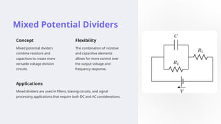
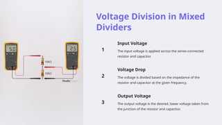
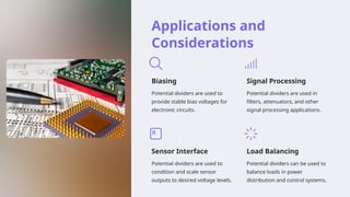
Introduction to
Potential Dividers
Potential dividers are essential circuits used to divide a voltage source
into smaller voltages. They can be constructed using resistors,
capacitors, or a combination of both. Understanding the principles of
potential dividers is crucial for designing and analyzing various electronic
systems.
By:
Mrs. Rachna Tyagi
Resistive Potential Dividers
Principle
A resistive potential divider uses two
or more resistors connected in series
to split a voltage across them.
Voltage Division
The output voltage depends on the
ratio of the resistor values, allowing
for precise voltage control.
Applications
Resistive dividers are used in
electronic devices, such as volume
controls, sensor circuits, and biasing
networks.
Voltage Division in
Resistive Dividers
1 Input Voltage
The input voltage is applied across the series-connected
resistors.
2 Voltage Drop
The voltage is divided across the resistors based on their
resistance values.
3 Output Voltage
The output voltage is the desired, lower voltage taken
from the junction of the resistors.
Advantages and
Disadvantages of
Resistive Dividers
1 Advantages
Simple design, easy to
calculate, and can handle
high currents.
2 Disadvantages
Load on the input source,
power dissipation, and
sensitivity to resistor value
changes.
Capacitive Potential Dividers
Principle
A capacitive potential divider uses
two or more capacitors connected in
series to split a voltage.
Voltage Division
The output voltage depends on the
ratio of the capacitor values, allowing
for precise voltage control.
Applications
Capacitive dividers are used in AC
circuits, such as audio filters, high-
frequency signal processing, and
coupling circuits.
Voltage Division in Capacitive Dividers
1
Input Voltage
The input voltage is applied across the series-connected
capacitors.
2
Voltage Drop
The voltage is divided across the capacitors based on their
capacitance values.
3
Output Voltage
The output voltage is the desired, lower voltage taken from the
junction of the capacitors.
Advantages and
Disadvantages of
Capacitive Dividers
1 Advantages
High input impedance, low
power dissipation, and
suitable for AC signals.
2 Disadvantages
Limited frequency range,
capacitor value changes
due to temperature and
aging, and limited current
handling.
Mixed Potential Dividers
Concept
Mixed potential dividers
combine resistors and
capacitors to create more
versatile voltage division
circuits.
Flexibility
The combination of resistive
and capacitive elements
allows for more control over
the output voltage and
frequency response.
Applications
Mixed dividers are used in filters, biasing circuits, and signal
processing applications that require both DC and AC considerations.
Voltage Division in Mixed
Dividers
Input Voltage
The input voltage is applied across the series-connected
resistor and capacitor.
Voltage Drop
The voltage is divided based on the impedance of the
resistor and capacitor at the given frequency.
Output Voltage
The output voltage is the desired, lower voltage taken from
the junction of the resistor and capacitor.
Applications and
Considerations
Biasing
Potential dividers are used to
provide stable bias voltages for
electronic circuits.
Signal Processing
Potential dividers are used in
filters, attenuators, and other
signal processing applications.
Sensor Interface
Potential dividers are used to
condition and scale sensor
outputs to desired voltage levels.
Load Balancing
Potential dividers can be used to
balance loads in power
distribution and control systems.

Introduction-to-Potential-Divideeers.pptx

  • 1.
    Introduction to Potential Dividers Potentialdividers are essential circuits used to divide a voltage source into smaller voltages. They can be constructed using resistors, capacitors, or a combination of both. Understanding the principles of potential dividers is crucial for designing and analyzing various electronic systems. By: Mrs. Rachna Tyagi
  • 2.
    Resistive Potential Dividers Principle Aresistive potential divider uses two or more resistors connected in series to split a voltage across them. Voltage Division The output voltage depends on the ratio of the resistor values, allowing for precise voltage control. Applications Resistive dividers are used in electronic devices, such as volume controls, sensor circuits, and biasing networks.
  • 3.
    Voltage Division in ResistiveDividers 1 Input Voltage The input voltage is applied across the series-connected resistors. 2 Voltage Drop The voltage is divided across the resistors based on their resistance values. 3 Output Voltage The output voltage is the desired, lower voltage taken from the junction of the resistors.
  • 4.
    Advantages and Disadvantages of ResistiveDividers 1 Advantages Simple design, easy to calculate, and can handle high currents. 2 Disadvantages Load on the input source, power dissipation, and sensitivity to resistor value changes.
  • 5.
    Capacitive Potential Dividers Principle Acapacitive potential divider uses two or more capacitors connected in series to split a voltage. Voltage Division The output voltage depends on the ratio of the capacitor values, allowing for precise voltage control. Applications Capacitive dividers are used in AC circuits, such as audio filters, high- frequency signal processing, and coupling circuits.
  • 6.
    Voltage Division inCapacitive Dividers 1 Input Voltage The input voltage is applied across the series-connected capacitors. 2 Voltage Drop The voltage is divided across the capacitors based on their capacitance values. 3 Output Voltage The output voltage is the desired, lower voltage taken from the junction of the capacitors.
  • 7.
    Advantages and Disadvantages of CapacitiveDividers 1 Advantages High input impedance, low power dissipation, and suitable for AC signals. 2 Disadvantages Limited frequency range, capacitor value changes due to temperature and aging, and limited current handling.
  • 8.
    Mixed Potential Dividers Concept Mixedpotential dividers combine resistors and capacitors to create more versatile voltage division circuits. Flexibility The combination of resistive and capacitive elements allows for more control over the output voltage and frequency response. Applications Mixed dividers are used in filters, biasing circuits, and signal processing applications that require both DC and AC considerations.
  • 9.
    Voltage Division inMixed Dividers Input Voltage The input voltage is applied across the series-connected resistor and capacitor. Voltage Drop The voltage is divided based on the impedance of the resistor and capacitor at the given frequency. Output Voltage The output voltage is the desired, lower voltage taken from the junction of the resistor and capacitor.
  • 10.
    Applications and Considerations Biasing Potential dividersare used to provide stable bias voltages for electronic circuits. Signal Processing Potential dividers are used in filters, attenuators, and other signal processing applications. Sensor Interface Potential dividers are used to condition and scale sensor outputs to desired voltage levels. Load Balancing Potential dividers can be used to balance loads in power distribution and control systems.