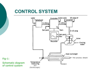
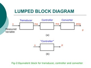
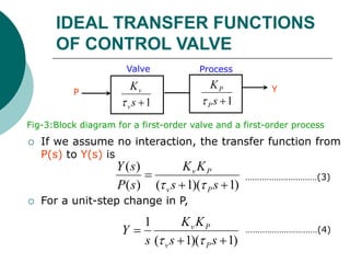
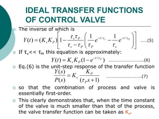
Lecture: 41
CONTROLLERS AND FINAL
CONTROL ELEMENTS
Ideal Transfer Function of
Control Valve
CONTROL SYSTEM
Fig-1:
Schematic diagram
of control system
LUMPED BLOCK DIAGRAM
Transducer Controller Converter
Measured
Variable
x ma ma psig
p
(a)
“Controller”
x p
(b)
Fig-2:Equivalent block for transducer, controller and converter
IDEAL TRANSFER FUNCTIONS
OF CONTROL VALVE
 A pneumatic valve always has some dynamic lag,
 which means that the stem motion does not respond
instantaneously to a change in the applied pressure from
the controller.
 From experiments conducted on pneumatic valves, it
has been found that the relationship between flow and
valve-top pressure for a linear valve can often be
represented by a first-order transfer function; thus
 Where Kv is the steady-state gain, i.e., the constant of
proportionality between steady-state flow rate and valve-
top pressure,
 and τv is the time constant of the valve.
1
)
(
)
(


s
K
s
P
s
Q
v
v

………………………………(1)
IDEAL TRANSFER FUNCTIONS
OF CONTROL VALVE
 In many practical systems, the time constant of the
valve is very small when compared with the time
constants of other components of the control system,
and the transfer function of the valve can be
approximated by a constant
 Under these conditions, the valve is said to contribute
negligible dynamic lag.
 To justify the approximation of a fast valve by a
transfer function, which is simply Kv, consider a first-
order valve and a first-order process connected in
series, as shown in Fig-3.
v
K
s
P
s
Q

)
(
)
( ………………………………(2)
IDEAL TRANSFER FUNCTIONS
OF CONTROL VALVE
 If we assume no interaction, the transfer function from
P(s) to Y(s) is
 For a unit-step change in P,
)
1
)(
1
(
)
(
)
(



s
s
K
K
s
P
s
Y
P
v
P
v


…………………………(3)
Valve Process
P Y
1

s
K
v
v
 1

s
K
P
P

Fig-3:Block diagram for a first-order valve and a first-order process
)
1
)(
1
(
1



s
s
K
K
s
Y
P
v
P
v


…………………………(4)
IDEAL TRANSFER FUNCTIONS
OF CONTROL VALVE
 The inverse of which is
 If τv<< τP, this equation is approximately:
 Eq.(6) is the unit-step response of the transfer function
 so that the combination of process and valve is
essentially first-order.
 This clearly demonstrates that, when the time constant
of the valve is much smaller than that of the process,
the valve transfer function can be taken as Kv.

















 
 P
v t
v
t
P
P
v
P
v
P
v e
e
K
K
t
Y 






 /
/ 1
1
1
)
(
)
( ……(5)
)
1
(
)
( / P
t
P
v e
K
K
t
Y 


 …………………………..(6)
)
1
(
)
(
)
(


s
K
K
s
P
s
Y
P
P
v

…………………………..(7)
IDEAL TRANSFER FUNCTIONS
OF CONTROL VALVE
 A typical pneumatic valve has a time constant of
the order of 1 sec.
 Many industrial processes behave as first-order
systems or as a series of first-order systems
having time constants that may range from a
minute to an hour.
 For these systems we have shown that the lag of
the valve is negligible, and we shall make frequent
use of this approximation.
Controllers and Final Control Elements.ppt

Controllers and Final Control Elements.ppt

  • 1.
    Lecture: 41 CONTROLLERS ANDFINAL CONTROL ELEMENTS Ideal Transfer Function of Control Valve
  • 2.
  • 3.
    LUMPED BLOCK DIAGRAM TransducerController Converter Measured Variable x ma ma psig p (a) “Controller” x p (b) Fig-2:Equivalent block for transducer, controller and converter
  • 4.
    IDEAL TRANSFER FUNCTIONS OFCONTROL VALVE  A pneumatic valve always has some dynamic lag,  which means that the stem motion does not respond instantaneously to a change in the applied pressure from the controller.  From experiments conducted on pneumatic valves, it has been found that the relationship between flow and valve-top pressure for a linear valve can often be represented by a first-order transfer function; thus  Where Kv is the steady-state gain, i.e., the constant of proportionality between steady-state flow rate and valve- top pressure,  and τv is the time constant of the valve. 1 ) ( ) (   s K s P s Q v v  ………………………………(1)
  • 5.
    IDEAL TRANSFER FUNCTIONS OFCONTROL VALVE  In many practical systems, the time constant of the valve is very small when compared with the time constants of other components of the control system, and the transfer function of the valve can be approximated by a constant  Under these conditions, the valve is said to contribute negligible dynamic lag.  To justify the approximation of a fast valve by a transfer function, which is simply Kv, consider a first- order valve and a first-order process connected in series, as shown in Fig-3. v K s P s Q  ) ( ) ( ………………………………(2)
  • 6.
    IDEAL TRANSFER FUNCTIONS OFCONTROL VALVE  If we assume no interaction, the transfer function from P(s) to Y(s) is  For a unit-step change in P, ) 1 )( 1 ( ) ( ) (    s s K K s P s Y P v P v   …………………………(3) Valve Process P Y 1  s K v v  1  s K P P  Fig-3:Block diagram for a first-order valve and a first-order process ) 1 )( 1 ( 1    s s K K s Y P v P v   …………………………(4)
  • 7.
    IDEAL TRANSFER FUNCTIONS OFCONTROL VALVE  The inverse of which is  If τv<< τP, this equation is approximately:  Eq.(6) is the unit-step response of the transfer function  so that the combination of process and valve is essentially first-order.  This clearly demonstrates that, when the time constant of the valve is much smaller than that of the process, the valve transfer function can be taken as Kv.                     P v t v t P P v P v P v e e K K t Y         / / 1 1 1 ) ( ) ( ……(5) ) 1 ( ) ( / P t P v e K K t Y     …………………………..(6) ) 1 ( ) ( ) (   s K K s P s Y P P v  …………………………..(7)
  • 8.
    IDEAL TRANSFER FUNCTIONS OFCONTROL VALVE  A typical pneumatic valve has a time constant of the order of 1 sec.  Many industrial processes behave as first-order systems or as a series of first-order systems having time constants that may range from a minute to an hour.  For these systems we have shown that the lag of the valve is negligible, and we shall make frequent use of this approximation.