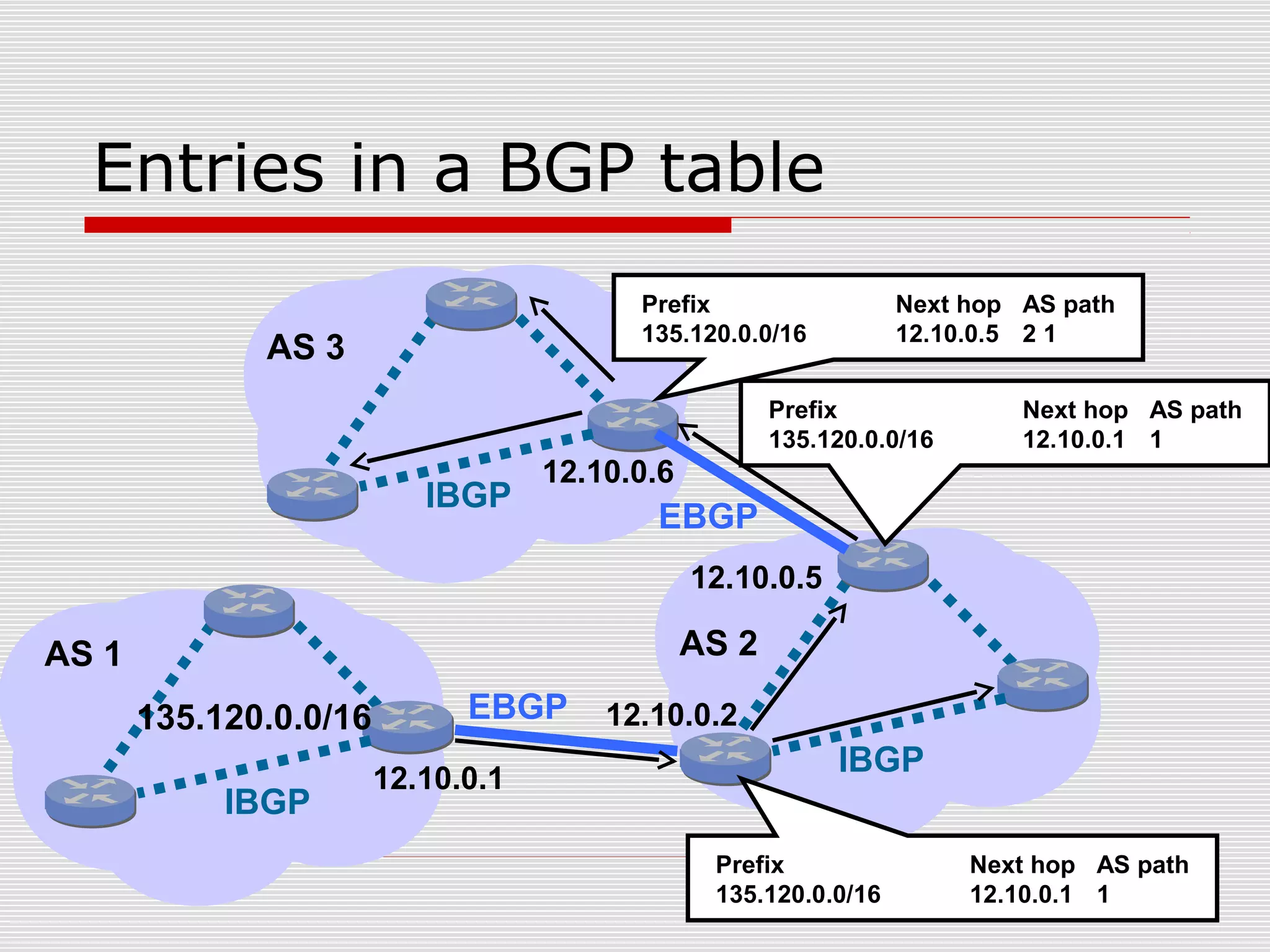
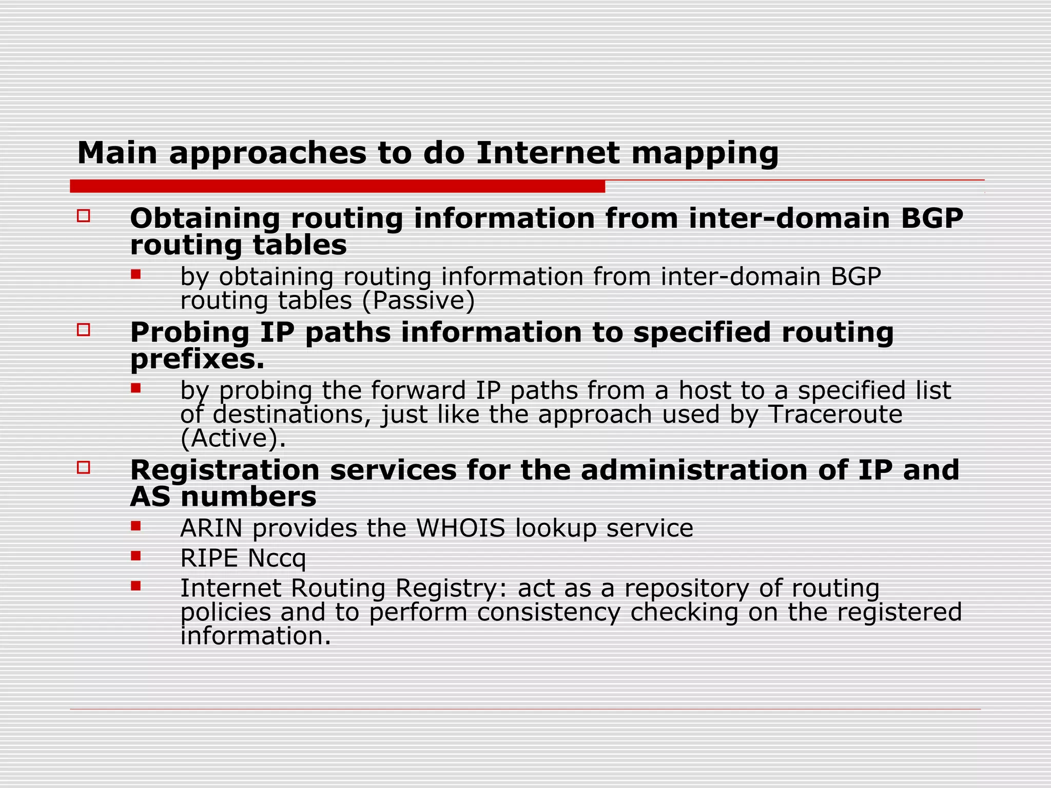
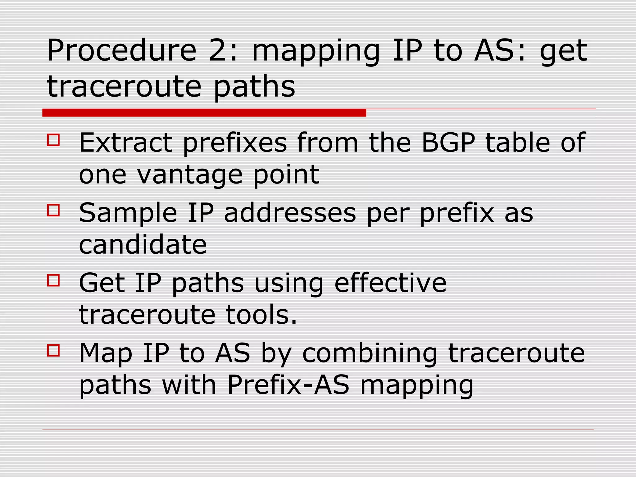
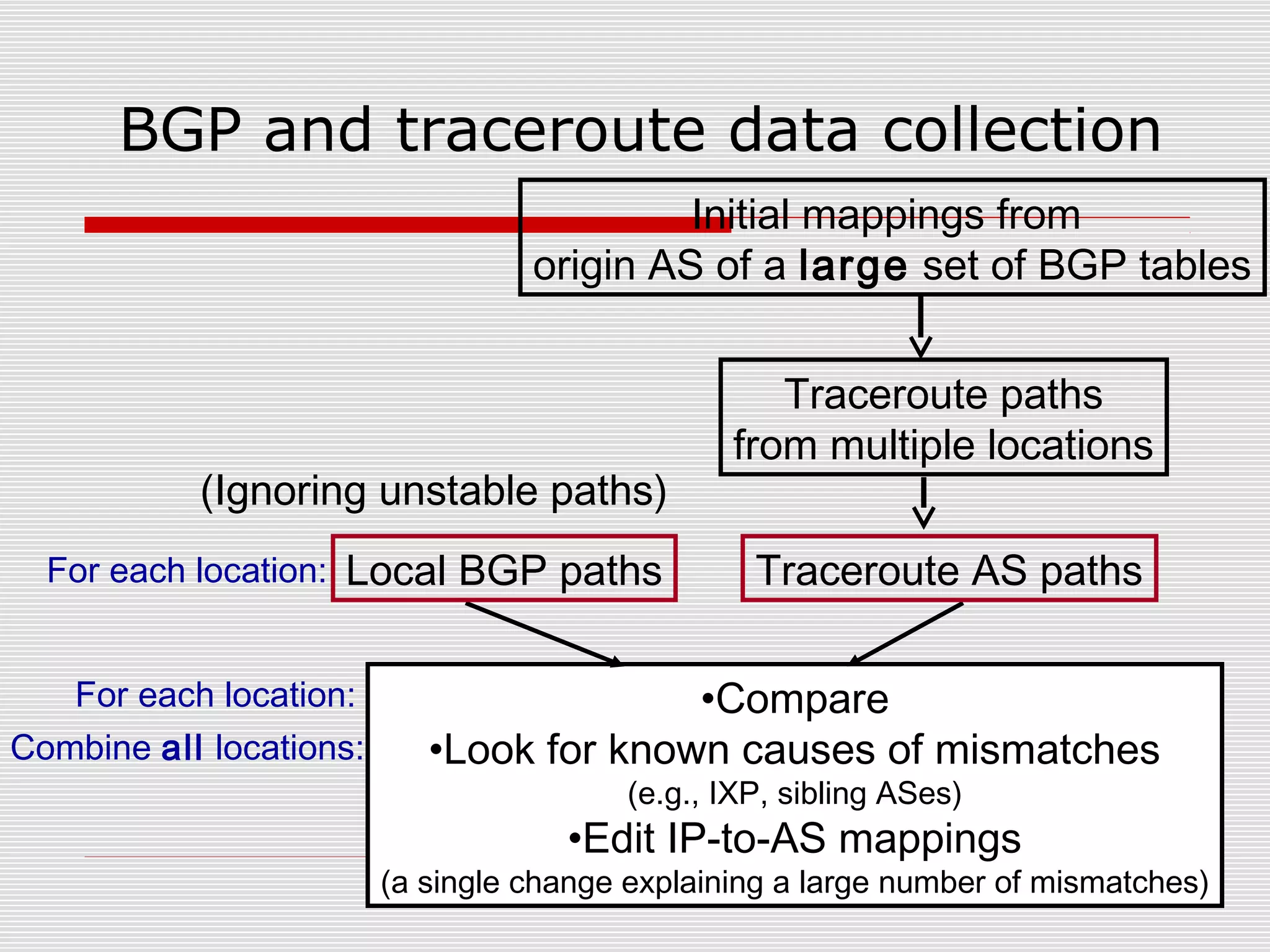
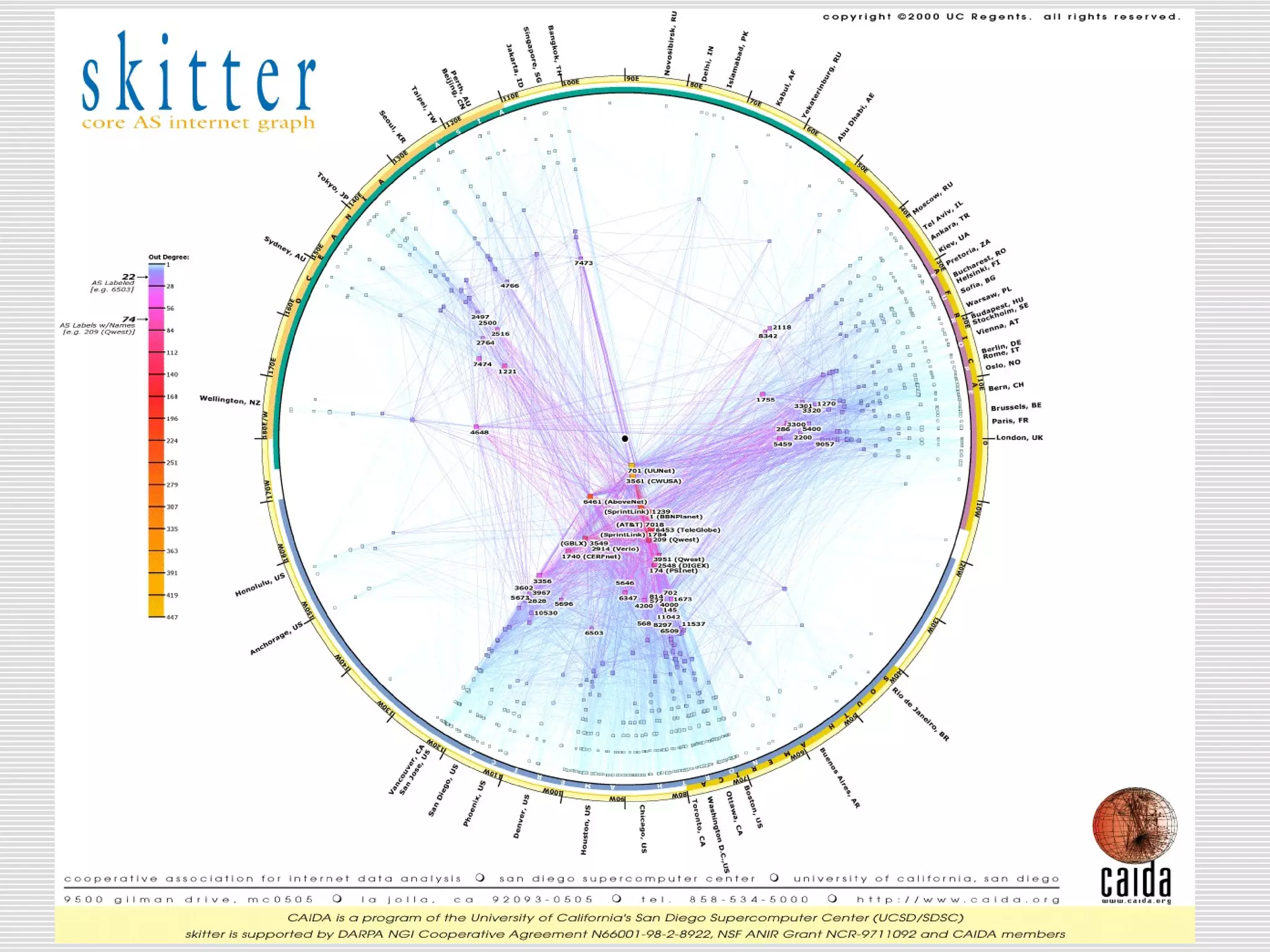
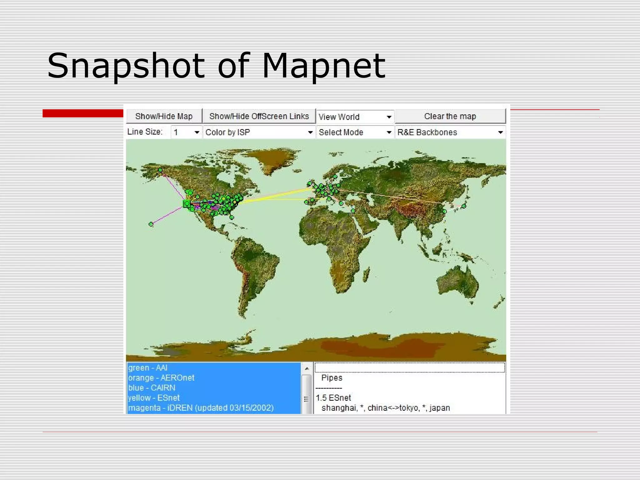
Internet Mapping and Visualization
Project Report in Adv.Data Communication Network
Jinfu Zheng Ling Liu
Outline
 Concepts of Internet Mapping
 Overview of BGP and Internet infrastructure
 Main approaches to collect internet mapping data
 Typical projects engaged in Internet Mapping
 Routviews project
 Relationship-based AS ranking
 Visulizing IPv4 internet topology at a
macroscopic scale
 Tools for visualization
 What can we get from Internet mapping?
What is Internet mapping?
 Map IP addresses or IP prefixes to
specific AS
 Figure out unique (adjacent) IP link
and AS link
 Infer AS relationships
 Depict critical components of the
Internet infrastructure
Internet routing architecture
IP traffic
Berkeley CNN
Level3
Internet
Calren GNN
Inter-domain
routing
Intra-domain
routing
What is the purpose of BGP?
 A network architecture is comprised of
multiple domains or ASes
 IGP (e.g. OSPF, IS-IS EIGRP) is run inside
AS
 EGP is used to connect ASes to exchange
network reachability information among
BGP routers (also called BGP speakers)
Entries in a BGP table
135.120.0.0/16
12.10.0.1
12.10.0.2
Prefix Next hop AS path
135.120.0.0/16 12.10.0.1 1
EBGP
IBGP
IBGP
IBGP
EBGP
12.10.0.5
12.10.0.6
AS 1 AS 2
AS 3
Prefix Next hop AS path
135.120.0.0/16 12.10.0.5 2 1
Prefix Next hop AS path
135.120.0.0/16 12.10.0.1 1
BGP routing process
Apply
input
policy
Routes
received
from peers
Select
best
route
Best
routes
Apply
output
policy
Routes
advertised
to peers
Routing
table
Forwarding
table
BGP is not shortest path routing!
Main approaches to do Internet mapping
 Obtaining routing information from inter-domain BGP
routing tables
 by obtaining routing information from inter-domain BGP
routing tables (Passive)
 Probing IP paths information to specified routing
prefixes.
 by probing the forward IP paths from a host to a specified list
of destinations, just like the approach used by Traceroute
(Active).
 Registration services for the administration of IP and
AS numbers
 ARIN provides the WHOIS lookup service
 RIPE Nccq
 Internet Routing Registry: act as a repository of routing
policies and to perform consistency checking on the registered
information.
Procedure 1:Extract Prefix-AS
mapping
 Get BGP table dumps by pick
multiple vantage points
 Extract prefix-AS (Originated)
mapping
Procedure 2: mapping IP to AS: get
traceroute paths
 Extract prefixes from the BGP table of
one vantage point
 Sample IP addresses per prefix as
candidate
 Get IP paths using effective
traceroute tools.
 Map IP to AS by combining traceroute
paths with Prefix-AS mapping
Different tracerout methods
 UDP
 UDP-Paris
 UDP-Paris DNS
 Sending UDP probes, using the reception of an ICMP
port unreachable message to indicate the
destination.
 ICMP
 ICMP-Paris
 An ICMP echo reply packet is received from the
destination in response to an ICMP echo request
packet (no concept of ports)
 TCP port 80
 A TCP packet is received from the destination in
response to a TCP probe
Traceroute method evaluation
 Complete IP paths
 Unique IP links
 Unique AS links
ICMP-based traceroute methods tend to successfully reach more
destinations, as well as collect greater number of AS links
UDP –based methods infer the greatest number of IP links, despite
reaching the fewest destinations.
TCP-often cause lots of complains, so it is seldom used.
BGP and traceroute data collection
Initial mappings from
origin AS of a large set of BGP tables
Traceroute paths
from multiple locations
•Compare
•Look for known causes of mismatches
(e.g., IXP, sibling ASes)
•Edit IP-to-AS mappings
(a single change explaining a large number of mismatches)
For each location:
Combine all locations:
Local BGP paths Traceroute AS pathsFor each location:
(Ignoring unstable paths)
Routeviews project
 Gathers BGP routing perspectives from BGP
routers distributed over more than 60
major ISPs worldwide
 The combined table typically has nearly
120K globally routable prefixes
 The data recorded can be obtained publicly
to study internet mapping and visualization
Tools used in Routeviews
 Cisco BRIB
 A script is run every two hours to collect the
BGP RIB and dampened routes.
 BGP beacon
 A BGP beacon is an unused, globally visible
prefix with KNOWN Announced/Withdrawal
schedule. The behaviour of this prefix can then
be analyzed closely.
 A controlled active measurement infrastructure
for continuous BGP monitoring
Relationship-based AS Ranking
1. Provide AS ranking based on business
relationship between ASes
2. Build an AS-level graph and annotate
links in the graph with inferred AS
relationships
3. Identify the AS-level hierarchy of
Internet
Typical AS relationships
 Provider-customer
 customer pay money for transit
 Peer-peer
 typically exchange respective customers’ traffic
for free
 Sibling-Sibling
 Mutual transit agreement
 Provide connectivity to the rest of the Internet
for each other
AS relationships translated into
BGP export rules
 Export to a provider or a peer
(upstream)
 Allowed: its routes and routes of its
customers and siblings
 Disallowed: routes learned from other
providers or peers
 Export to a customer or a sibling
(downstream)
 In reverse, AS level relationship can
be figured out by analyzing the AS
paths in the routing table
Visulizing IPv4 internet topology at
a macroscopic scale (CAIDA)
• Goals of the project
 Tracking global IP level connectivity by sending packets from a set
of source monitors to hundreds of thousands of destinations
 Stratifying the current IPv4 address space.
• 5,568,419 IP links (immediately adjacent addresses in a traceroute-link
path)
• 13 monitor vantages (observation points)
• Probing 48,535,339 /24s prefixes
• The project map each IP address to the AS responsible for routing
traffic to it.
Tools used by CAIDA (Skitter or Ark)
• Skitter probes with Traceroute based on ICMP echo
requests
• Team probing, divide the work of probing into a
random destination in every routed /24
• Within 48 hours for a team of 13 monitors probing 7
million /24’s prefixes
Limitations of the topology data
obtained with the skitter tool
 Depends on whether ICMP echo_reply
can be received to an Echo_request.
 Can not map IP paths behind firewalls
or NAT.
 Some destinations have IP addresses
assigned by DHCP
 The coverage is far from complete.
Analysis of the results
 The highly “core-centric” nature of certain
ASes based in North America.
 ISPs in Europe and Asia have many peering
relationships with ISPs in the US.
 Fewer links directly between ISPs in Asia
and Europe
 Both technical (cable and router placement
and management) as well as policy
(business cost models and geopolitical
considerations) factors contribute to
peering arrangements
 UUnet and Level3 are the two biggest ISPs
Mapnet
 A tool for visualizing the
infrastructure of multiple international
backbone providers simultaneously.
 Each backbone infrastructure is
divided into a group of nodes and
pipes.
 Drawing these nodes and pipes on
their geographical location
Snapshot of Mapnet
Otter
 For visualizing arbitrary network data
expressed as a set of nodes, links, or
paths.
 Data independence, can be used to
visualize multicast and unicast topology
dataset, core BGP routing tables,
reachability and delay measurements,
SNMP data, and website directory
structures.
Sample of Otter
Walrus is a
three
dimensional
visualization
tool
What can we get from internet mapping?
 Internet mapping is to depict the internet
infrastructure by probing or analyzing the unique IP
links, AS links, and complete IP paths.
 Provide a way or model of thinking about the BGP
protocols in the Internet
 Identify important routing anomalies
 Lost reachability, persistent flapping, large traffic
shifts
 Aid in the placement of mirror servers
Thanks & Questions

InternetMappingAndVisualizationGroup5JinfuZhengAndLingLiu

  • 1.
    Internet Mapping andVisualization Project Report in Adv.Data Communication Network Jinfu Zheng Ling Liu
  • 2.
    Outline  Concepts ofInternet Mapping  Overview of BGP and Internet infrastructure  Main approaches to collect internet mapping data  Typical projects engaged in Internet Mapping  Routviews project  Relationship-based AS ranking  Visulizing IPv4 internet topology at a macroscopic scale  Tools for visualization  What can we get from Internet mapping?
  • 3.
    What is Internetmapping?  Map IP addresses or IP prefixes to specific AS  Figure out unique (adjacent) IP link and AS link  Infer AS relationships  Depict critical components of the Internet infrastructure
  • 4.
    Internet routing architecture IPtraffic Berkeley CNN Level3 Internet Calren GNN Inter-domain routing Intra-domain routing
  • 5.
    What is thepurpose of BGP?  A network architecture is comprised of multiple domains or ASes  IGP (e.g. OSPF, IS-IS EIGRP) is run inside AS  EGP is used to connect ASes to exchange network reachability information among BGP routers (also called BGP speakers)
  • 6.
    Entries in aBGP table 135.120.0.0/16 12.10.0.1 12.10.0.2 Prefix Next hop AS path 135.120.0.0/16 12.10.0.1 1 EBGP IBGP IBGP IBGP EBGP 12.10.0.5 12.10.0.6 AS 1 AS 2 AS 3 Prefix Next hop AS path 135.120.0.0/16 12.10.0.5 2 1 Prefix Next hop AS path 135.120.0.0/16 12.10.0.1 1
  • 7.
    BGP routing process Apply input policy Routes received frompeers Select best route Best routes Apply output policy Routes advertised to peers Routing table Forwarding table BGP is not shortest path routing!
  • 8.
    Main approaches todo Internet mapping  Obtaining routing information from inter-domain BGP routing tables  by obtaining routing information from inter-domain BGP routing tables (Passive)  Probing IP paths information to specified routing prefixes.  by probing the forward IP paths from a host to a specified list of destinations, just like the approach used by Traceroute (Active).  Registration services for the administration of IP and AS numbers  ARIN provides the WHOIS lookup service  RIPE Nccq  Internet Routing Registry: act as a repository of routing policies and to perform consistency checking on the registered information.
  • 9.
    Procedure 1:Extract Prefix-AS mapping Get BGP table dumps by pick multiple vantage points  Extract prefix-AS (Originated) mapping
  • 10.
    Procedure 2: mappingIP to AS: get traceroute paths  Extract prefixes from the BGP table of one vantage point  Sample IP addresses per prefix as candidate  Get IP paths using effective traceroute tools.  Map IP to AS by combining traceroute paths with Prefix-AS mapping
  • 11.
    Different tracerout methods UDP  UDP-Paris  UDP-Paris DNS  Sending UDP probes, using the reception of an ICMP port unreachable message to indicate the destination.  ICMP  ICMP-Paris  An ICMP echo reply packet is received from the destination in response to an ICMP echo request packet (no concept of ports)  TCP port 80  A TCP packet is received from the destination in response to a TCP probe
  • 12.
    Traceroute method evaluation Complete IP paths  Unique IP links  Unique AS links ICMP-based traceroute methods tend to successfully reach more destinations, as well as collect greater number of AS links UDP –based methods infer the greatest number of IP links, despite reaching the fewest destinations. TCP-often cause lots of complains, so it is seldom used.
  • 13.
    BGP and traceroutedata collection Initial mappings from origin AS of a large set of BGP tables Traceroute paths from multiple locations •Compare •Look for known causes of mismatches (e.g., IXP, sibling ASes) •Edit IP-to-AS mappings (a single change explaining a large number of mismatches) For each location: Combine all locations: Local BGP paths Traceroute AS pathsFor each location: (Ignoring unstable paths)
  • 14.
    Routeviews project  GathersBGP routing perspectives from BGP routers distributed over more than 60 major ISPs worldwide  The combined table typically has nearly 120K globally routable prefixes  The data recorded can be obtained publicly to study internet mapping and visualization
  • 15.
    Tools used inRouteviews  Cisco BRIB  A script is run every two hours to collect the BGP RIB and dampened routes.  BGP beacon  A BGP beacon is an unused, globally visible prefix with KNOWN Announced/Withdrawal schedule. The behaviour of this prefix can then be analyzed closely.  A controlled active measurement infrastructure for continuous BGP monitoring
  • 16.
    Relationship-based AS Ranking 1.Provide AS ranking based on business relationship between ASes 2. Build an AS-level graph and annotate links in the graph with inferred AS relationships 3. Identify the AS-level hierarchy of Internet
  • 17.
    Typical AS relationships Provider-customer  customer pay money for transit  Peer-peer  typically exchange respective customers’ traffic for free  Sibling-Sibling  Mutual transit agreement  Provide connectivity to the rest of the Internet for each other
  • 18.
    AS relationships translatedinto BGP export rules  Export to a provider or a peer (upstream)  Allowed: its routes and routes of its customers and siblings  Disallowed: routes learned from other providers or peers  Export to a customer or a sibling (downstream)  In reverse, AS level relationship can be figured out by analyzing the AS paths in the routing table
  • 19.
    Visulizing IPv4 internettopology at a macroscopic scale (CAIDA) • Goals of the project  Tracking global IP level connectivity by sending packets from a set of source monitors to hundreds of thousands of destinations  Stratifying the current IPv4 address space. • 5,568,419 IP links (immediately adjacent addresses in a traceroute-link path) • 13 monitor vantages (observation points) • Probing 48,535,339 /24s prefixes • The project map each IP address to the AS responsible for routing traffic to it.
  • 20.
    Tools used byCAIDA (Skitter or Ark) • Skitter probes with Traceroute based on ICMP echo requests • Team probing, divide the work of probing into a random destination in every routed /24 • Within 48 hours for a team of 13 monitors probing 7 million /24’s prefixes
  • 21.
    Limitations of thetopology data obtained with the skitter tool  Depends on whether ICMP echo_reply can be received to an Echo_request.  Can not map IP paths behind firewalls or NAT.  Some destinations have IP addresses assigned by DHCP  The coverage is far from complete.
  • 23.
    Analysis of theresults  The highly “core-centric” nature of certain ASes based in North America.  ISPs in Europe and Asia have many peering relationships with ISPs in the US.  Fewer links directly between ISPs in Asia and Europe  Both technical (cable and router placement and management) as well as policy (business cost models and geopolitical considerations) factors contribute to peering arrangements  UUnet and Level3 are the two biggest ISPs
  • 24.
    Mapnet  A toolfor visualizing the infrastructure of multiple international backbone providers simultaneously.  Each backbone infrastructure is divided into a group of nodes and pipes.  Drawing these nodes and pipes on their geographical location
  • 25.
  • 26.
    Otter  For visualizingarbitrary network data expressed as a set of nodes, links, or paths.  Data independence, can be used to visualize multicast and unicast topology dataset, core BGP routing tables, reachability and delay measurements, SNMP data, and website directory structures.
  • 27.
  • 28.
  • 29.
    What can weget from internet mapping?  Internet mapping is to depict the internet infrastructure by probing or analyzing the unique IP links, AS links, and complete IP paths.  Provide a way or model of thinking about the BGP protocols in the Internet  Identify important routing anomalies  Lost reachability, persistent flapping, large traffic shifts  Aid in the placement of mirror servers
  • 30.

Editor's Notes

  • #5 Internet routing is a hierarchical architecture: intra-domain routing and inter-domain routing. Intra-domain routing happens within an AS while interdomain routing happens between different ASes. The goal of internet mapping is to figure out all these AS links and IP links between the source and destination.
  • #7 Three typical fields. Hop is a entry in a router
  • #8 Procedure of selecting the routes. BGP routing process is a combination of technical and business relationship. Input policy is to decide whether to accept the route received from peers Output policy is to decide whether to broadcast the best routes to the peers. Routing table: Forwarding table: base on routing table to delivery the routes.
  • #9 The last approach (verification) is to verify the results of the first two approaches for internet mapping They are database, the users can register their IP address ,or AS number also they can inquire the information of specific IP address or AS number.
  • #10 We can use tools such as scripts program to download the contents of the BGP tables.
  • #11 Why do we need to select prefixes to get sample IPs per prefix Identifying all live IP addresses is challengingSome prefixes are never used to route traffic because of more specific subnets in the routing table.
  • #12 The first traceroute tool is based on the interactions in udp .
  • #13 Comlete IP paths and others are to do internet mapping UDP is suitable to find completed IP links within an AS.
  • #14 There are often some limitations existed in the two approaches. For example, in tracerroute method, some IP addresses are non-routable, Also, there are some anomalies existing in BGP tables. So, one better way to find the routing path is to combine these two methods. If there are mismatches between these two sets of paths, we should analyze the causes for these mismatches, and figure the correct forward paths according to the specific situation, such as IXP ( Internet exchange points) or sibling ASes
  • #15 Next, we will focus on some specific projects and their accomplishments.
  • #17 One of the project that based on Routeviews is AS ranking.
  • #19 So we know that AS relationships have to be translated into policies in BGP routing. in another aspect, we can also figure out AS relationships from BGP routing table data.
  • #20 This is a project conducted by CAIDA (cooperative Association for Internet Data Analysis)
  • #23 Let’s think of the center point as the North pole (the arctic pole). The link color reflects the AS outdegree. The out degree of an AS is the number of net-hop AS that were observed accepting traffic from this AS
  • #25 In the end, we will talk about some tools for visualization
  • #26 Each backbone infrastructure is divided into a group of nodes and pipes. Drawing these nodes and pipes on their geographical location
  • #28 For visualizing arbitrary network data expressed as a set of nodes, links, or paths.
  • #29 It is often used to depict a spanning tree