INTERLOCKING PAVEMENT
1
CONTENT
• HISTORY
• INTRODUCTION
• CLASSIFICATION
• METHODOLOGY
• SPECIFICATIONS
• BENEFITS
• LIMITATION
• APPLICATION
2
HISTORY
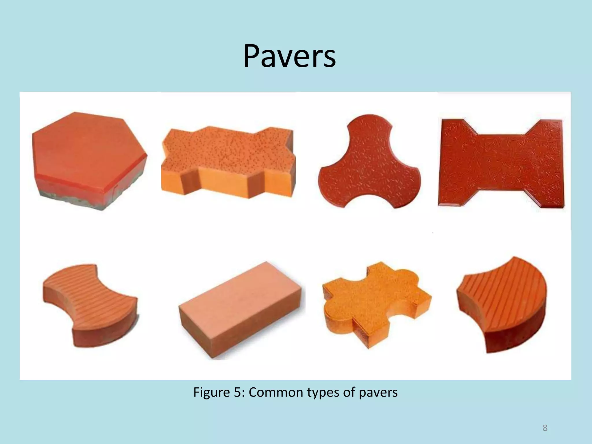
• An early version of interlocking concrete pavement dates back
to the Roman Empire when The Appian Way was built from
stone paving on an aggregate base in 312 B.C.
• Used as a main route for military
supplies, it connected Rome to
Brindisi, Apulia, in southeast Italy.
• The road is 350 miles long about
20 feet wide and has held up for
more than 2,000 years.
3
Figure 1: The Appian Way
Contd.
• As City Engineer with the City of Ripon, Matt Machado
developed interlocking concrete pavement as a roadway
standard, adopted by City Council.
• With the standard in place the
City constructed more than 1.3
million square feet between
2005 and 2008.
• This included the high-profile
Main Street in historic downtown
Ripon with 50,000 sf of
interlocking concrete pavement.
4
Figure 2: Main Street in historic
downtown Ripon, California
Contd.
• Located in Westley, California at exit 441 on I-5, Howard Road
handles a tremendous amount of heavy truck traffic.
• Asphalt pavement had failed, the County looked at
interlocking concrete pavers as the innovative solution.
5
Figure 3: Failed Asphalt on Howard
Road
Figure 4: New Howard Road
INTRODUCTION
• Permeable interlocking concrete pavement, also referred to
as PICP, consists solid concrete paving units called ‘pavers’
with joints that create openings in the pavement surface
when assembled into a pattern.
• The joints are filled with permeable aggregates that allow
water to freely enter the surface.
• The permeable surface allows flow rates as high as 1,000
in./hr (2,540 cm/hr).
• The paving units are placed on a bedding layer of permeable
aggregates which rests over a base and subbase of open-
graded aggregates.
6
Contd.
• The base and subbase store water and allow it to infiltrate
into the soil subgrade.
• Perforated underdrains in the base or subbase are used to
remove water that does not infiltrate within a given design
period, typically 48 to 72 hours.
7
Pavers
8
Figure 5: Common types of pavers
9
Figure 6: Cross-section of interlocking pavement
Classification
• A partial infiltration design is providing drainage to
accommodate some water that does on enter low infiltration
soils.
• PICP over high infiltration subgrade soils may not require an
underdrain(s) and these are called are called full infiltration
designs.
• The use of a geo-membrane to restrict infiltration into the soil
subgrade is often called a no infiltration design.
10
METHODOLOGY
Design
• Consideration is given to hydrologic design for storm water
management and to structural design to support anticipated
vehicle axle loads.
• The thicker of the two bases from structural and hydrologic
designs is selected.
11
Pre-construction meeting
• Walk through the site with builder/contractor/ subcontractor
to review erosion and sediment control plan/storm water
pollution prevention plan.
• Determine when PICP is built in project construction
sequence and confirm specified measures for PICP protection
and surface cleaning
• Aggregate material storage locations identified (hard surface
or on geotextile)
• Sediment management
• Access routes for delivery and construction vehicles identified
12
Excavation
• Utilities located and marked by local service
• Excavated area marked with paint and/or stakes
• Excavation size and location conforms to plan
• The stakes should be marked to
establish grades, or have string
lines pulled and tied to them.
• Slopes should be a minimum of
1.5%.
• Protect temporary soil stockpiles
from erosion from water and wind
13Figure 7: Excavation of the soil subgrade.
Soil Subgrade
• Rocks and roots removed, voids refilled with open-graded
aggregate
• Soil compacted to specifications and field tested with density
measurements per specifications
• No groundwater seepage or
standing water
• Low, wet areas can be stabilized
with a layer of crushed stone.
• The surface of the stone is even
with the top of the compacted
soil subgrade.
14Figure 8: Compacting the soil subgrade.
Applying Geotextiles (Optional)
• Geotextile fabric(impermeable membrane) may be used in
areas where soil remains saturated part of the year
• As a separation layer, they prevent
soil from being pressed into the
aggregate base under loads
• When geotextiles are used they
preserve the load bearing capacity
of the base over a greater length of
time than placement without them
• Protect the foundation of
near by structure
15
Figure 9: Application of the geotextile under
aggregate base.
Spreading and Compacting the Sub-
base and/or Base Aggregates
• Spread and compact the base in 4 to 6 in. (l00 to 150 mm)
lifts.
• Non freeze-thaw areas with well-drained soils should have at
least a 6 in. (150 mm) thick base.
• When spread and compacted, the aggregate base should be
at its optimum moisture.
• If the surface allow ingress of
bedding sand, a choke course
of fine material is spread and
compacted into the surface, or a
bitumen tack coat can be applied.
16
Figure 10: Base compaction with a vibratory
roller.
Placing and Screeding
the Bedding Sand
• Masonry sand for mortar should never be used for bedding,
nor should limestone screenings or stone dust.
• The bedding sand should have symmetrical particles,
generally sharp, washed, with no foreign material.
• Bedding sand should be
spread and screeded to
a nominal 1 in. (25 mm)
thickness
• The sand is screeded
with a true strike board.
17Figure 11: Screeding the bedding sand.
Placing the Concrete Pavers
• Concrete pavers can be placed in many patterns.
• Joint widths between the pavers should be consistent and be
between 1/16 and 3/16 in. (2 and 5 mm).
• Cut pavers should be used to fill gaps along the edge of the
pavement. Pavers are cut with a double bladed splitter.
• After an area of pavers is placed, it should be compacted with
a vibrating plate compactor
• Dry joint sand is swept into the joints and the pavers
compacted again until the joints are full.
• Excess sand is then removed.
• A small amount of settling is typical of all flexible pavements.
• Optional sealers or joint sand stabilizers may be applied.
18
19
Figure 12: Placing the
concrete pavers.
Figure 13: Saw cutting
pavers.
Figure 14: Excess sand swept
from the finished surface
Figure 15: Compacting Figure 16: Spreading and
sweeping joint sand.
Figure 17: Vibrating sand
into the joints.
Specifications
• Foundation Walls: At least 10 ft (3 m) from foundations with
no waterproofing or drainage
• Water Supply: At least 100 ft (30 m) from municipal water
supply wells
• Concrete sand conforming to CSA A23.1 is recommended - it's
the same sand mixed into concrete pavers and poured, cast-
in-place concrete.
• The ICPI only recommends the use of base material meeting
gradation requirements of ASTM-D2940 with 6 to 12% passing
the no. 200 (80 micron) sieve.
20
Contd.
• ICPI recommends a minimum base thickness of 4 inches (100
mm) for residential patios and walkways and 6 inches (150
mm) for driveways in non freeze thaw areas.
• In colder climates these base thicknesses are increased and
most contractors will use 6 and 10 inches (150 mm and 250
mm) respectively.
• For non-vehicular uses such as embankment stabilization, the
maximum slope is determined by the angle of repose of the
bedding sand, typically around 35 to 38 degrees.
• For vehicular traffic, the highest slope in use is about 10
degrees.
21
What are the benefits of concrete pavers?
• Concrete pavers do not crack like asphalt or poured-in-place
concrete - each unit has joints that allow for a small amount
of movement without cracking.
• Concrete pavers are easy to repair and/or replace, especially
when repairs are being done to the base or underground
utilities. Asphalt, concrete, and stamped concrete can't make
this claim.
• Resists deterioration from freeze-thaw cycles.
22
• Concrete pavers come in many shapes and colours.
• Paving stones should last over 30 years, which is much longer
than alternative pavements under normal residential use.
• Capable of wet weather (light rain) installation
• Immediately ready for traffic upon completion, no time
needed for curing
• Upto 100% infiltration depending on the design
23
LIMITATION
• PICP should not be used in areas subject to loading/unloading
or storage of hazardous materials.
• It is generally not placed in areas with high depth to seasonal
water tables.
• It should not be used in very cold areas, where temperature
drops below freezing point of water.
• When load is eccentric pavers may come out or shift from
their position.
24
Application
PICP is used for:
• Walkways
• Driveways
• Parking lots
• Alleys
• Low-speed roads
• Road shoulders etc.
25
26

Interlocking pavement

  • 1.
  • 2.
    CONTENT • HISTORY • INTRODUCTION •CLASSIFICATION • METHODOLOGY • SPECIFICATIONS • BENEFITS • LIMITATION • APPLICATION 2
  • 3.
    HISTORY • An earlyversion of interlocking concrete pavement dates back to the Roman Empire when The Appian Way was built from stone paving on an aggregate base in 312 B.C. • Used as a main route for military supplies, it connected Rome to Brindisi, Apulia, in southeast Italy. • The road is 350 miles long about 20 feet wide and has held up for more than 2,000 years. 3 Figure 1: The Appian Way
  • 4.
    Contd. • As CityEngineer with the City of Ripon, Matt Machado developed interlocking concrete pavement as a roadway standard, adopted by City Council. • With the standard in place the City constructed more than 1.3 million square feet between 2005 and 2008. • This included the high-profile Main Street in historic downtown Ripon with 50,000 sf of interlocking concrete pavement. 4 Figure 2: Main Street in historic downtown Ripon, California
  • 5.
    Contd. • Located inWestley, California at exit 441 on I-5, Howard Road handles a tremendous amount of heavy truck traffic. • Asphalt pavement had failed, the County looked at interlocking concrete pavers as the innovative solution. 5 Figure 3: Failed Asphalt on Howard Road Figure 4: New Howard Road
  • 6.
    INTRODUCTION • Permeable interlockingconcrete pavement, also referred to as PICP, consists solid concrete paving units called ‘pavers’ with joints that create openings in the pavement surface when assembled into a pattern. • The joints are filled with permeable aggregates that allow water to freely enter the surface. • The permeable surface allows flow rates as high as 1,000 in./hr (2,540 cm/hr). • The paving units are placed on a bedding layer of permeable aggregates which rests over a base and subbase of open- graded aggregates. 6
  • 7.
    Contd. • The baseand subbase store water and allow it to infiltrate into the soil subgrade. • Perforated underdrains in the base or subbase are used to remove water that does not infiltrate within a given design period, typically 48 to 72 hours. 7
  • 8.
  • 9.
    9 Figure 6: Cross-sectionof interlocking pavement
  • 10.
    Classification • A partialinfiltration design is providing drainage to accommodate some water that does on enter low infiltration soils. • PICP over high infiltration subgrade soils may not require an underdrain(s) and these are called are called full infiltration designs. • The use of a geo-membrane to restrict infiltration into the soil subgrade is often called a no infiltration design. 10
  • 11.
    METHODOLOGY Design • Consideration isgiven to hydrologic design for storm water management and to structural design to support anticipated vehicle axle loads. • The thicker of the two bases from structural and hydrologic designs is selected. 11
  • 12.
    Pre-construction meeting • Walkthrough the site with builder/contractor/ subcontractor to review erosion and sediment control plan/storm water pollution prevention plan. • Determine when PICP is built in project construction sequence and confirm specified measures for PICP protection and surface cleaning • Aggregate material storage locations identified (hard surface or on geotextile) • Sediment management • Access routes for delivery and construction vehicles identified 12
  • 13.
    Excavation • Utilities locatedand marked by local service • Excavated area marked with paint and/or stakes • Excavation size and location conforms to plan • The stakes should be marked to establish grades, or have string lines pulled and tied to them. • Slopes should be a minimum of 1.5%. • Protect temporary soil stockpiles from erosion from water and wind 13Figure 7: Excavation of the soil subgrade.
  • 14.
    Soil Subgrade • Rocksand roots removed, voids refilled with open-graded aggregate • Soil compacted to specifications and field tested with density measurements per specifications • No groundwater seepage or standing water • Low, wet areas can be stabilized with a layer of crushed stone. • The surface of the stone is even with the top of the compacted soil subgrade. 14Figure 8: Compacting the soil subgrade.
  • 15.
    Applying Geotextiles (Optional) •Geotextile fabric(impermeable membrane) may be used in areas where soil remains saturated part of the year • As a separation layer, they prevent soil from being pressed into the aggregate base under loads • When geotextiles are used they preserve the load bearing capacity of the base over a greater length of time than placement without them • Protect the foundation of near by structure 15 Figure 9: Application of the geotextile under aggregate base.
  • 16.
    Spreading and Compactingthe Sub- base and/or Base Aggregates • Spread and compact the base in 4 to 6 in. (l00 to 150 mm) lifts. • Non freeze-thaw areas with well-drained soils should have at least a 6 in. (150 mm) thick base. • When spread and compacted, the aggregate base should be at its optimum moisture. • If the surface allow ingress of bedding sand, a choke course of fine material is spread and compacted into the surface, or a bitumen tack coat can be applied. 16 Figure 10: Base compaction with a vibratory roller.
  • 17.
    Placing and Screeding theBedding Sand • Masonry sand for mortar should never be used for bedding, nor should limestone screenings or stone dust. • The bedding sand should have symmetrical particles, generally sharp, washed, with no foreign material. • Bedding sand should be spread and screeded to a nominal 1 in. (25 mm) thickness • The sand is screeded with a true strike board. 17Figure 11: Screeding the bedding sand.
  • 18.
    Placing the ConcretePavers • Concrete pavers can be placed in many patterns. • Joint widths between the pavers should be consistent and be between 1/16 and 3/16 in. (2 and 5 mm). • Cut pavers should be used to fill gaps along the edge of the pavement. Pavers are cut with a double bladed splitter. • After an area of pavers is placed, it should be compacted with a vibrating plate compactor • Dry joint sand is swept into the joints and the pavers compacted again until the joints are full. • Excess sand is then removed. • A small amount of settling is typical of all flexible pavements. • Optional sealers or joint sand stabilizers may be applied. 18
  • 19.
    19 Figure 12: Placingthe concrete pavers. Figure 13: Saw cutting pavers. Figure 14: Excess sand swept from the finished surface Figure 15: Compacting Figure 16: Spreading and sweeping joint sand. Figure 17: Vibrating sand into the joints.
  • 20.
    Specifications • Foundation Walls:At least 10 ft (3 m) from foundations with no waterproofing or drainage • Water Supply: At least 100 ft (30 m) from municipal water supply wells • Concrete sand conforming to CSA A23.1 is recommended - it's the same sand mixed into concrete pavers and poured, cast- in-place concrete. • The ICPI only recommends the use of base material meeting gradation requirements of ASTM-D2940 with 6 to 12% passing the no. 200 (80 micron) sieve. 20
  • 21.
    Contd. • ICPI recommendsa minimum base thickness of 4 inches (100 mm) for residential patios and walkways and 6 inches (150 mm) for driveways in non freeze thaw areas. • In colder climates these base thicknesses are increased and most contractors will use 6 and 10 inches (150 mm and 250 mm) respectively. • For non-vehicular uses such as embankment stabilization, the maximum slope is determined by the angle of repose of the bedding sand, typically around 35 to 38 degrees. • For vehicular traffic, the highest slope in use is about 10 degrees. 21
  • 22.
    What are thebenefits of concrete pavers? • Concrete pavers do not crack like asphalt or poured-in-place concrete - each unit has joints that allow for a small amount of movement without cracking. • Concrete pavers are easy to repair and/or replace, especially when repairs are being done to the base or underground utilities. Asphalt, concrete, and stamped concrete can't make this claim. • Resists deterioration from freeze-thaw cycles. 22
  • 23.
    • Concrete paverscome in many shapes and colours. • Paving stones should last over 30 years, which is much longer than alternative pavements under normal residential use. • Capable of wet weather (light rain) installation • Immediately ready for traffic upon completion, no time needed for curing • Upto 100% infiltration depending on the design 23
  • 24.
    LIMITATION • PICP shouldnot be used in areas subject to loading/unloading or storage of hazardous materials. • It is generally not placed in areas with high depth to seasonal water tables. • It should not be used in very cold areas, where temperature drops below freezing point of water. • When load is eccentric pavers may come out or shift from their position. 24
  • 25.
    Application PICP is usedfor: • Walkways • Driveways • Parking lots • Alleys • Low-speed roads • Road shoulders etc. 25
  • 26.