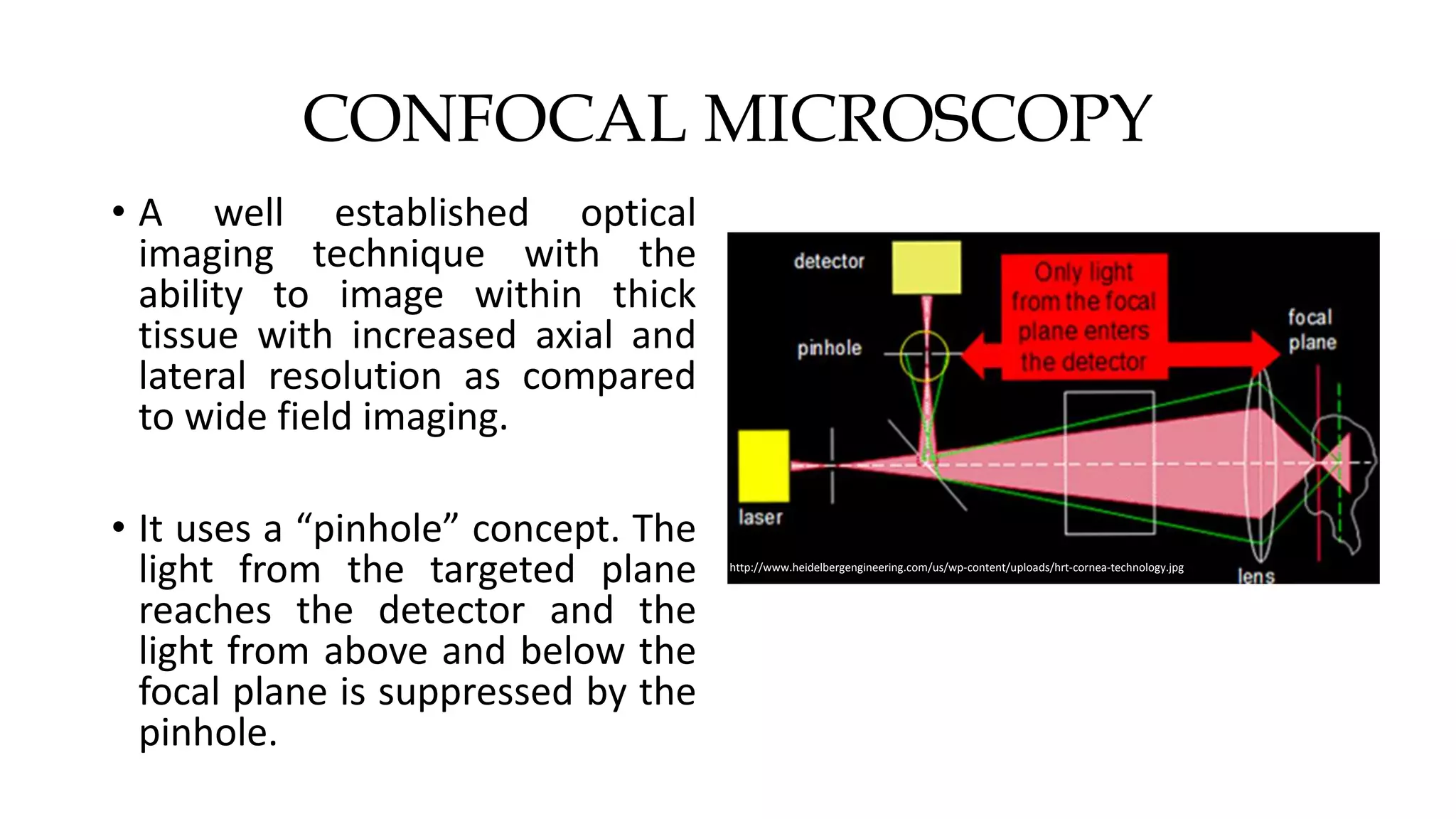
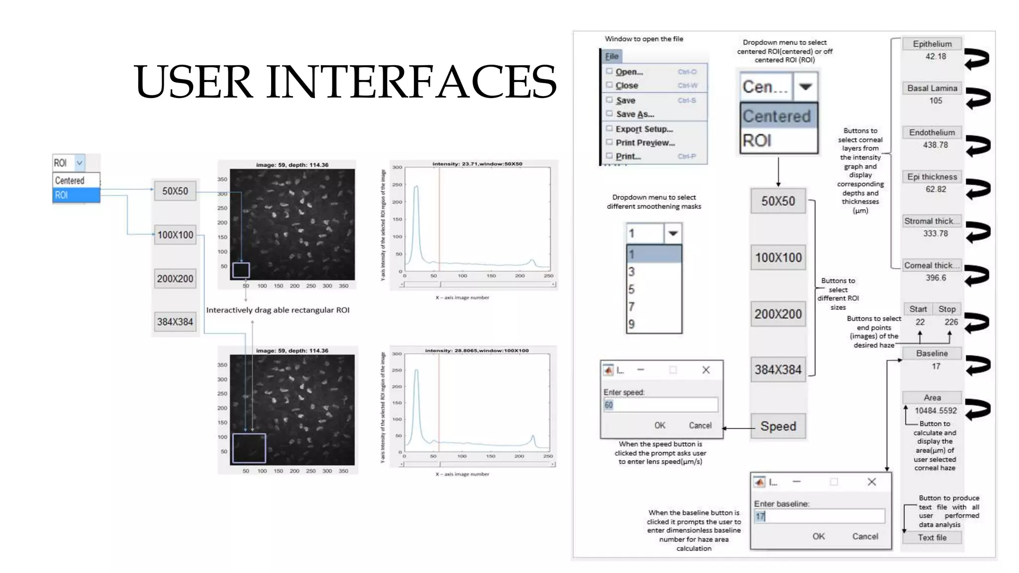
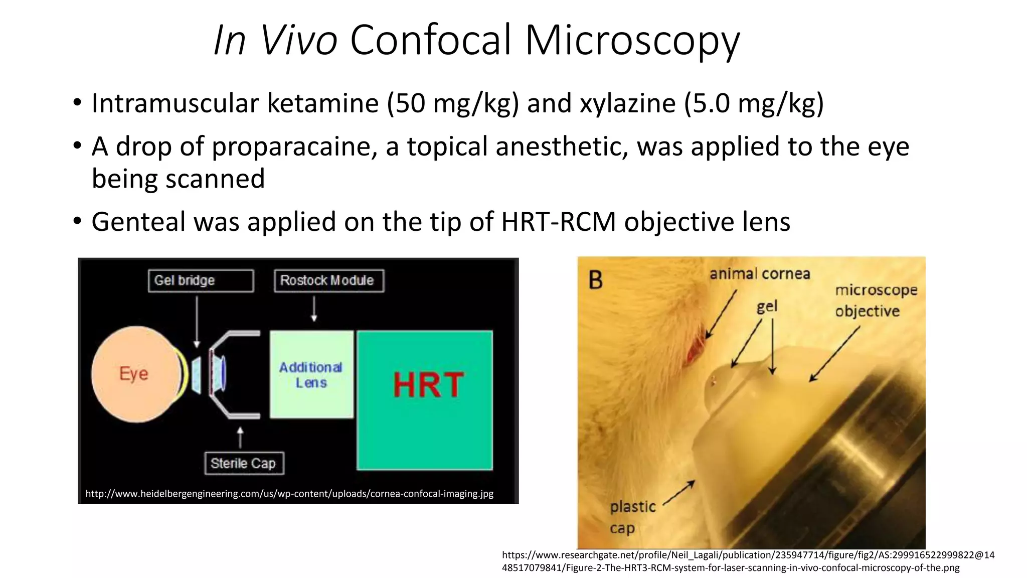
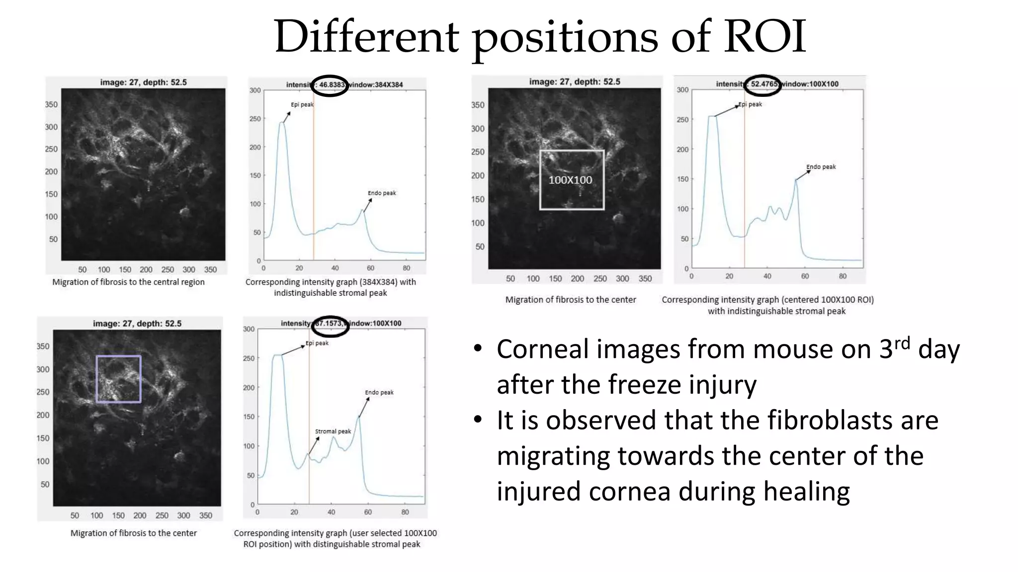
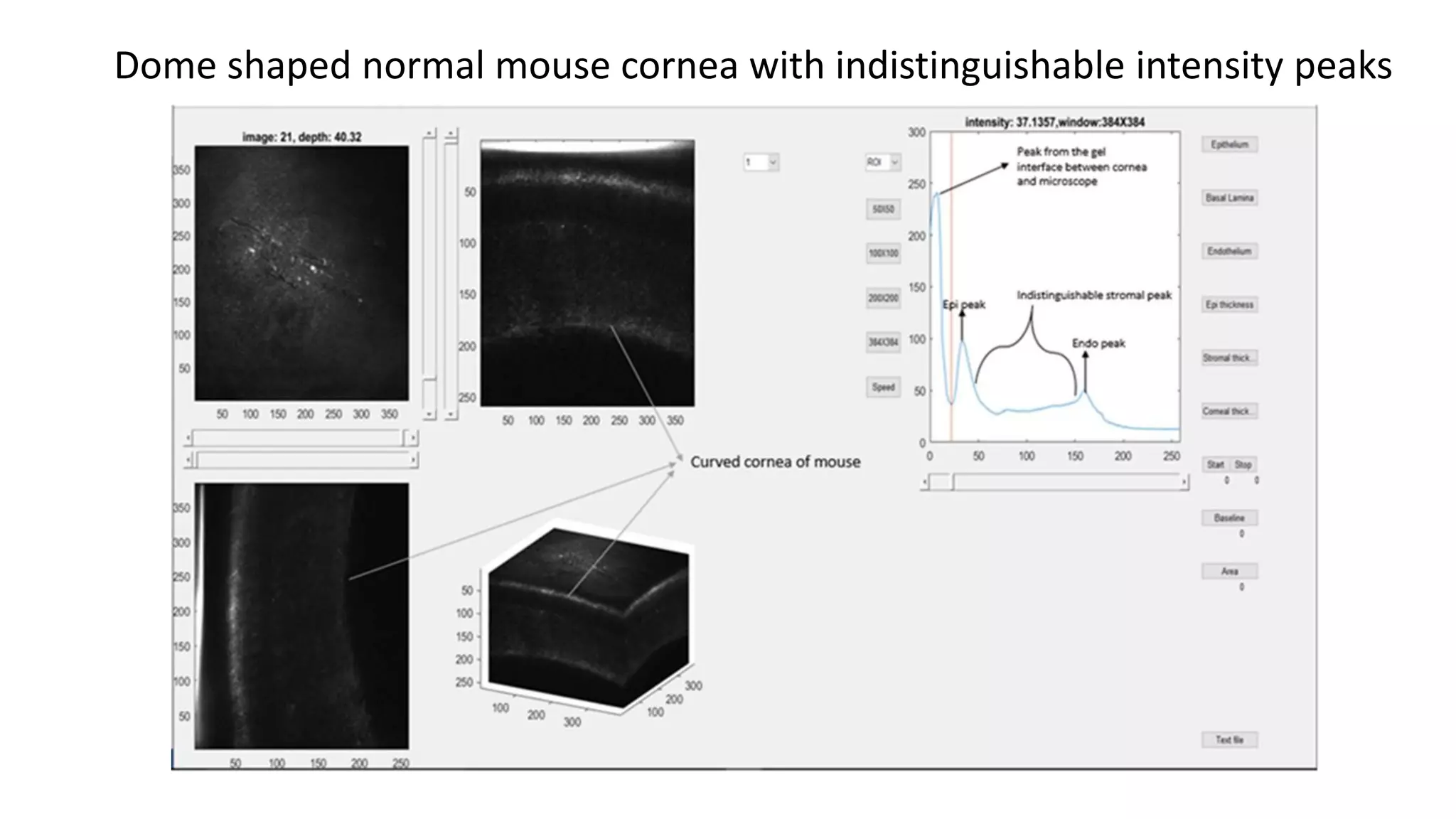
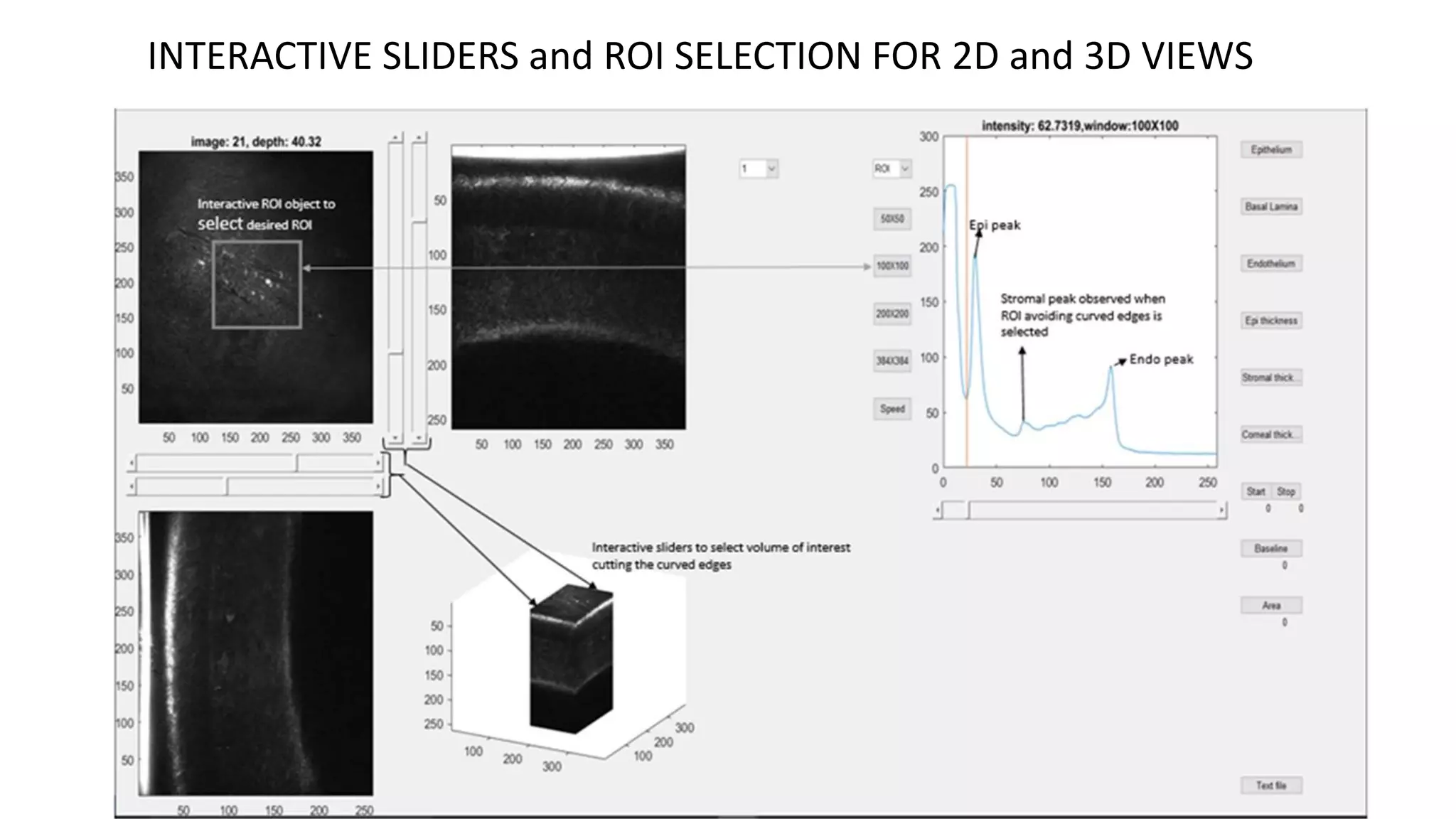
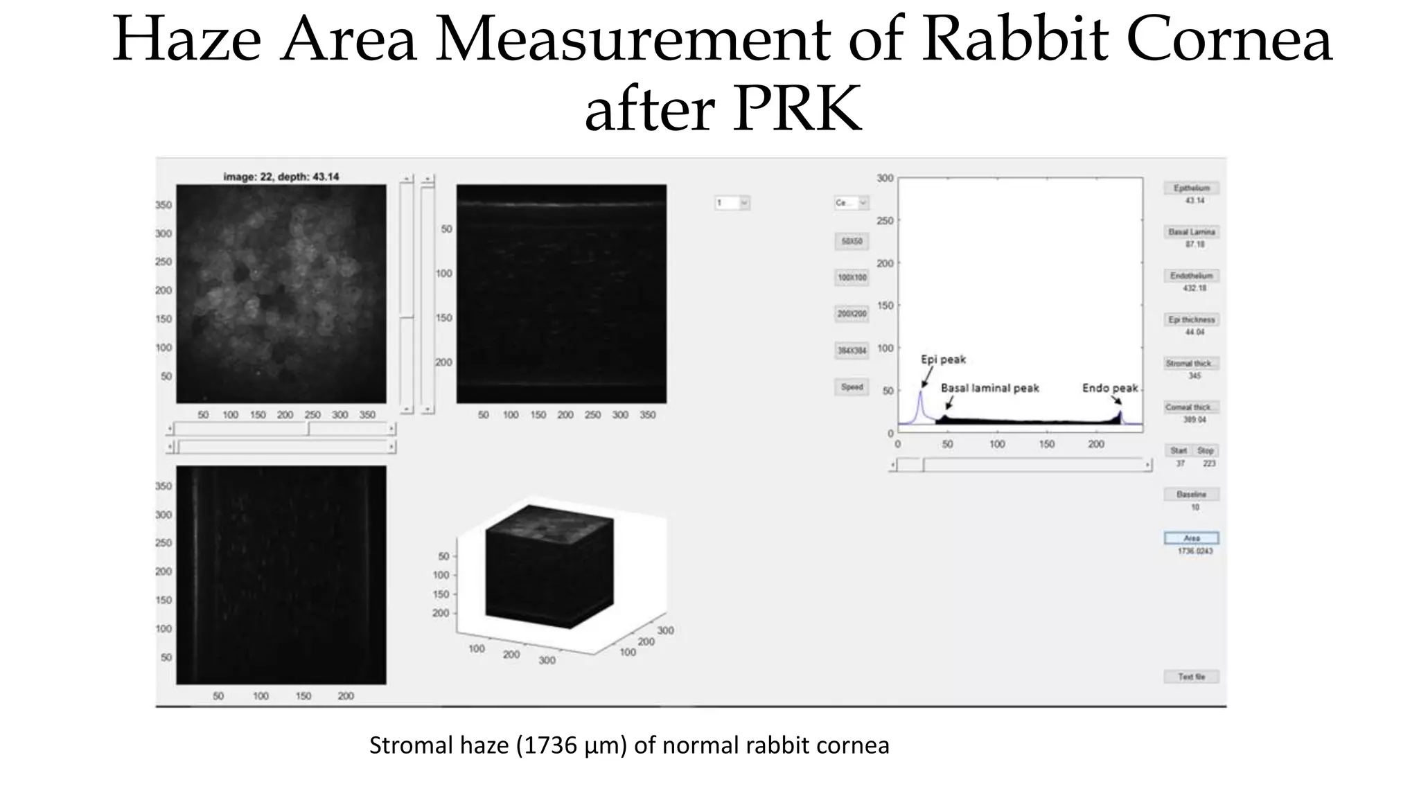
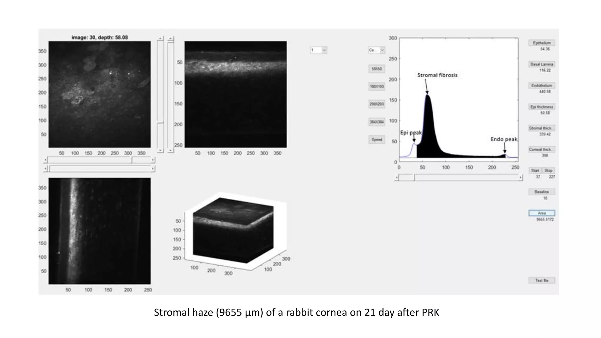
INTERACTIVE ANALYTICAL TOOL FOR
QUANTITATIVE CORNEAL CONFOCAL
IMAGING IN VIVO
Madhavi Tippani
Graduate student - University of Texas at Arlington
Graduate Research Assistant -
University of Texas South Western Medical Center
WELCOME
COMMITTEE MEMBERS
Supervising professor - Dr. Matthew Petroll, Ph.D. (Professor,
Ophthalmology, University of Texas Southwestern Medical Center)
Track advisor – Dr. Hanli Liu, Ph.D. (Professor, Bioengineering
department, University of Texas at Arlington)
Dr. George Alexandrakis, Ph.D. (Professor, Bioengineering department,
University of Texas at Arlington)
TABLE OF CONTENTS
• Introduction – Eye, Cornea, Corneal disorders, Treatments
• Confocal Microscopy
• In Vivo Confocal Microscopy – TSCM (Tandem Scanning Confocal Microscopy),
Confoscan 4, HRT-RCM (Heidelberg Retinal Tomograph with Rostock Corneal
Module)
• Confocal Microscopy Through Focusing (CMTF)
• Thesis Goals
• MATLAB – Program Architecture, User Interfaces
• Image Processing and Analysis
• Animal Models
• Results
• Future Work
EYE
• Vision a process where the light
reflected from objects in the
environment is translated into a
mental image.
• The two main refractive components
in the eye are the cornea and the
lens.
• Cornea is a refractive surface that
contributes to about two/thirds of
the optical power of the eye.
https://askabiologist.asu.edu/sites/default/files/resources/articles/seecolor/eye-anatomy-1000.jpg
CORNEA
• Epithelium (~50 µm) – important
refractive component of the cornea
present at the air/tissue interface.
• Stroma (~550 µm) – makes up 90%
of a corneal thickness, with sparsely
distributed keratocytes, cells
important for wound healing.
• Endothelium (~5 µm) – regulates
solute transport between aqueous
humor and stroma. Reference: https://www.refractiveeyesurgery.org/Interactive-Eye#/cornea
Reference: https://www.refractiveeyesurgery.org/The-Human-Eye/The-Cornea
COMMON CORNEAL DISORDERS
• Myopia
(nearsightedness),
hyperopia
(farsightedness),
astigmatism,
keratoconus,
infectious keratitis,
etc.
http://eyesfor.me/en/home/visual-dysfunction/astigmatism.html
TREATMENT
Apart from antibiotics, contact lens or steroid drops, the following
procedures can treat the above mentioned corneal disorders:
(a) photorefractive keratectomy (PRK) and laser-assisted in situ
keratomileusis (LASIK), that concentrate on correcting the shape of the
cornea.
(b) corneal crosslinking procedures that improve the strength of the
collagen fiber bonding.
(c) Keratoplasty to transplant all or part of the affected corneal tissue.
CONFOCAL MICROSCOPY
• A well established optical
imaging technique with the
ability to image within thick
tissue with increased axial and
lateral resolution as compared
to wide field imaging.
• It uses a “pinhole” concept. The
light from the targeted plane
reaches the detector and the
light from above and below the
focal plane is suppressed by the
pinhole.
http://www.heidelbergengineering.com/us/wp-content/uploads/hrt-cornea-technology.jpg
Reference: https://www.youtube.com/watch?v=GkQJadpKYOE
IN VIVO CONFOCAL MICROSCOPY
OF CORNEA
• The ability to optically section through thick tissues makes confocal
microscopy suitable for in vivo studies.
• This unique technique is used for a number of clinical applications to
study corneal tissue in living subjects.
• The tandem scanning confocal microscope (TSCM, a spinning disk
confocal), the Confoscan 4 (scanning slit system), and the Heidelberg
Retina Tomograph with Rostock Cornea Module (HRT-RCM, a
scanning laser system) are the three confocal systems that have been
developed for corneal imaging.
Tandem Scanning Confocal Microscope(TSCM)
1. Light enters through 20 µm diameter pinholes in Nipkow disc
2. Light is focused on the tissue
3. Reflected light is focused back onto conjugate
pinhole on opposite side of disc.
4. Low light level camera detects image.
- Lens and focal plane position moved using an
Oriel encoder mike motor and controller
- 24X objective lens (0.75 NA)
- Less than 1% of the transmitted light is recovered
- Low signal to noise ratio
CONFOSCAN 4
• A variable slit real-time scanning confocal microscope
• Pinholes are replaced with independent adjustable slits, one
at each optical plane, and the beam splitter is replaced with
a 2-sided mirror which scans the image of the slit over the
cornea
• User-friendly instrument with automated alignment and
scanning software
• Better signal to noise ratio (SNR) is achieved at the expense
of axial resolution (thicker optical sectioning)
• 40X objective lens (0.75 NA)
http://www.microscopyu.com/articles/confocal
/images/resonantscanningfigure3.jpg
Heidelberg Retinal Tomograph with Rostock
Corneal Module (HRT-RCM)
• Laser scanning confocal microscope with 670-nm laser
beam (<1 µm diameter)
• Scans are performed in raster pattern using horizontal
and vertical oriented scanning mirrors.
• Reflected light is descanned using the same mirrors and
directed to a PMT using beam splitter
• Thinner optical sectioning with axial resolution of 7.6
µm (9 µm for TSCM and 24 µm for Confoscan),
• 63X objective lens (0.9 NA)
IMAGE SLICE
CONFOCAL MICROCOPY THROUGH
FOCUSING (CMTF)
• To collect and quantify three-dimensional
information from the cornea, a technique called CMTF is
used.
• CMTF scans are obtained by rapidly focusing through the
cornea at high constant lens speed thereby optically
sectioning the cornea in a direction perpendicular to the
z-axis from (epithelium to endothelium).
• The z-axis intensity profile obtained from CMTF scans
provides information about depth and thickness of
corneal cell layers, since different corneal sublayers
produce different reflective intensities when imaged
using confocal microscopy.
Z-axis optical
sectioning
LIMITATIONS
• Automated z-scans limited to ~60 µm
• Focusing over larger distances must be performed
manually
• The stand does not swivel for proper positioning
• The standard HRT-RCM software collects only 100
images in a sequential scan , with a larger step size
(>5 µm) between images in a CMTF stack of the
full-thickness cornea.
http://www.ophthalmologymanagement.com/content/arc
hive/2008/july/supplements/omd_dibg/images/omd_july_
dibg_suppl_a04_fig05.jpg
MODIFICATIONS
• Thumbscrew is removed
• Newport TRA25CC
Motorized actuator with
DC servo motor is coupled
to the microscope scan
head using a spring loaded
shaft
• Hands-free control of
focusing using a Newport
joystick
• HRT-RCM mounted on a
slit-lamp stand
CMTF application for quantitative analysis of cornea that effectively reconstructs the 2D and 3D
views of corneal image stacks from the HRT-RCM; built on Microsoft Visual C++ (version 6.0)
object oriented programming
GOALS
• Previous software is cumbersome and any modification or addition of
features requires extensive programming experience in C++
• The main goals of this thesis project were to:
(a) Develop and test a new CMTF application in a more user friendly
and widely available programming environment, with all effective
features for providing quantitative data from CMTF image stacks
(b) Add a new feature for interactively selecting the center of the
desired Region of Interest (ROI) from the image stack for curve
calculation (Confo always positions the ROI on the center of the
image for curve calculation).
• Widely available and user-friendly
• Easier to learn compared to visual C++
• Built-in graphics and extensive image processing toolbox
• MATLAB compiler was used to deploy
the tool with MATLAB runtime included
in the package
• Event driven programming and objects
• MATLAB version R2015a, 64-bit on Microsoft Windows 10 Home (Version
1511), 64-bit Operating System and; x64 based Intel core processor, 8GB
RAM was used for programming.
http://www.nersc.gov/assets/Vis/matlablogo.jpg
PROGRAM
ARCHITECTURE
• All images in a sequence are combined into a
single “.vol” file
• Volume files are decoded using the header file
information
• Each image contains a 384 byte header
followed by the 384X384 pixel data
• The timestamp of each image is
decoded for depth calculation
Cornea 1
USER INTERFACES
IMAGE AND SIGNAL ANALYSIS
• INTENSITY CURVE (centered and off centered): Plot of average
intensity of the image from selected ROI versus the respective image
number
• IMAGE DEPTH: Timestamp of image is decoded and time difference
between the image slices is calculated. Depth (distance = velocity x
time) is then calculated on known scan speed
• SUBLAYER THICKNESS: Epithelial, stromal and corneal thicknesses are
the difference between basal laminal depth and epithelial depth, the
endothelial depth and basal laminal depth, and the endothelial depth
and epithelial depth respectively.
• STROMAL HAZE AREA: Summation of the products of difference of
depth of consecutive images with its average intensity
METHODS
• Animal Models
(a) New Zealand white rabbits (3-4kg) were used as subjects for Freeze
Injury (FI) and Photorefractive keratectomy (PRK)
- FI: A stainless steel probe of 3mm diameter cooled with liquid nitrogen
was applied to the anterior and central corneal surface of one eye per
animal three times for 10 seconds each time
- PRK: A VISX STAR S4/IR Excimer Laser System was used to remove the
epithelium and anterior stroma from central region of the cornea (8
mm diameter) from one eye of each rabbit
(a) Normal C57BL/6 mice (25-30g, 10-14 weeks old) were also used as
subjects for FI and to test the system on a smaller cornea with higher
radius of curvature
In Vivo Confocal Microscopy
• Intramuscular ketamine (50 mg/kg) and xylazine (5.0 mg/kg)
• A drop of proparacaine, a topical anesthetic, was applied to the eye
being scanned
• Genteal was applied on the tip of HRT-RCM objective lens
http://www.heidelbergengineering.com/us/wp-content/uploads/cornea-confocal-imaging.jpg
https://www.researchgate.net/profile/Neil_Lagali/publication/235947714/figure/fig2/AS:299916522999822@14
48517079841/Figure-2-The-HRT3-RCM-system-for-laser-scanning-in-vivo-confocal-microscopy-of-the.png
RESULTS
• Epithelial, stromal and corneal thicknesses of rabbit and mouse cornea were
calculated using the present application cornea1, and directly compared to
the values obtained from the previous application
Sublayer thickness of normal rabbit cornea from “Confo”
CONFO
CORNEA 1
• The measured epithelial, stromal and corneal thickness of mouse cornea were
43.5µm, 79.7µm and 123.2µm, respectively, in both the applications
Sublayer thickness of normal rabbit cornea from “Cornea1”
Cell Activation and Wound Healing
The 2D and 3D CMTF images (Fig 3.7) of the rabbit cornea on the 7th day after a freeze injury
The highly
refractive,
scattered and
elongated
corneal
keratocytes
indicate
fibroblast
activation and
migration
during wound
healing
Different sizes of ROI
Intensity curves of a
rabbit cornea on the
14th day after a freeze
injury
(a) intensity curve
obtained when all of the
pixels (384X384) were
used
(b) intensity curve
obtained from the center
100X100 pixels. Higher
peak are observed
Different positions of ROI
• Corneal images from mouse on 3rd day
after the freeze injury
• It is observed that the fibroblasts are
migrating towards the center of the
injured cornea during healing
Dome shaped normal mouse cornea with indistinguishable intensity peaks
INTERACTIVE SLIDERS and ROI SELECTION FOR 2D and 3D VIEWS
Haze Area Measurement of Rabbit Cornea
after PRK
Stromal haze (1736 µm) of normal rabbit cornea
Stromal haze (9655 µm) of a rabbit cornea on 21 day after PRK
Short term goals:
(1) To increase the application speed.
(2) To change the present 3D view to cabinet view to
make it efficient for clinical use.
FUTURE WORK
Long term goals
(1) In rare cases, because of the slight movement of the cornea, the
images produced to form a stack may not be in proper alignment.
Software called ‘ImageJ’ is currently being used to align the images
in the stack when necessary.
This feature of image alignment could be incorporated in the
software, thereby eliminating the use of other applications. In
addition, a Fourier Transform algorithm could be used to quantify
cell alignment during wound healing.
(2) To develop techniques to reduce the noise in the images, to correct
motion artifacts caused by tissue movements due to heartbeat,
respiration or involuntary patient movements during the scan.
SUMMARY
One important tool that is used to access corneal pathology and
monitor the response to various treatments is in vivo confocal
microscopy.
Heidelberg Retinal Tomograph with Rostock Corneal Module (HRT-
RCM) confocal microscope produces high resolution and contrast
images of cornea.
Cornea 1 an interactive software application was developed to
overcome the limitations of an earlier application ‘Confo’. The
application effectively works for image reconstruction and quantitative
analysis of the corneal data from HRT-RCM.
Dr. Hanli Liu Dr. W. Matthew Petroll Dr. George Alexandrakis
INTERACTIVE ANALYTICAL TOOL FOR CORNEAL CONFOCAL IMAGING

INTERACTIVE ANALYTICAL TOOL FOR CORNEAL CONFOCAL IMAGING

  • 1.
    INTERACTIVE ANALYTICAL TOOLFOR QUANTITATIVE CORNEAL CONFOCAL IMAGING IN VIVO Madhavi Tippani Graduate student - University of Texas at Arlington Graduate Research Assistant - University of Texas South Western Medical Center
  • 2.
    WELCOME COMMITTEE MEMBERS Supervising professor- Dr. Matthew Petroll, Ph.D. (Professor, Ophthalmology, University of Texas Southwestern Medical Center) Track advisor – Dr. Hanli Liu, Ph.D. (Professor, Bioengineering department, University of Texas at Arlington) Dr. George Alexandrakis, Ph.D. (Professor, Bioengineering department, University of Texas at Arlington)
  • 3.
    TABLE OF CONTENTS •Introduction – Eye, Cornea, Corneal disorders, Treatments • Confocal Microscopy • In Vivo Confocal Microscopy – TSCM (Tandem Scanning Confocal Microscopy), Confoscan 4, HRT-RCM (Heidelberg Retinal Tomograph with Rostock Corneal Module) • Confocal Microscopy Through Focusing (CMTF) • Thesis Goals • MATLAB – Program Architecture, User Interfaces • Image Processing and Analysis • Animal Models • Results • Future Work
  • 4.
    EYE • Vision aprocess where the light reflected from objects in the environment is translated into a mental image. • The two main refractive components in the eye are the cornea and the lens. • Cornea is a refractive surface that contributes to about two/thirds of the optical power of the eye. https://askabiologist.asu.edu/sites/default/files/resources/articles/seecolor/eye-anatomy-1000.jpg
  • 5.
    CORNEA • Epithelium (~50µm) – important refractive component of the cornea present at the air/tissue interface. • Stroma (~550 µm) – makes up 90% of a corneal thickness, with sparsely distributed keratocytes, cells important for wound healing. • Endothelium (~5 µm) – regulates solute transport between aqueous humor and stroma. Reference: https://www.refractiveeyesurgery.org/Interactive-Eye#/cornea
  • 6.
  • 7.
    COMMON CORNEAL DISORDERS •Myopia (nearsightedness), hyperopia (farsightedness), astigmatism, keratoconus, infectious keratitis, etc. http://eyesfor.me/en/home/visual-dysfunction/astigmatism.html
  • 8.
    TREATMENT Apart from antibiotics,contact lens or steroid drops, the following procedures can treat the above mentioned corneal disorders: (a) photorefractive keratectomy (PRK) and laser-assisted in situ keratomileusis (LASIK), that concentrate on correcting the shape of the cornea. (b) corneal crosslinking procedures that improve the strength of the collagen fiber bonding. (c) Keratoplasty to transplant all or part of the affected corneal tissue.
  • 9.
    CONFOCAL MICROSCOPY • Awell established optical imaging technique with the ability to image within thick tissue with increased axial and lateral resolution as compared to wide field imaging. • It uses a “pinhole” concept. The light from the targeted plane reaches the detector and the light from above and below the focal plane is suppressed by the pinhole. http://www.heidelbergengineering.com/us/wp-content/uploads/hrt-cornea-technology.jpg
  • 10.
  • 11.
    IN VIVO CONFOCALMICROSCOPY OF CORNEA • The ability to optically section through thick tissues makes confocal microscopy suitable for in vivo studies. • This unique technique is used for a number of clinical applications to study corneal tissue in living subjects. • The tandem scanning confocal microscope (TSCM, a spinning disk confocal), the Confoscan 4 (scanning slit system), and the Heidelberg Retina Tomograph with Rostock Cornea Module (HRT-RCM, a scanning laser system) are the three confocal systems that have been developed for corneal imaging.
  • 12.
    Tandem Scanning ConfocalMicroscope(TSCM) 1. Light enters through 20 µm diameter pinholes in Nipkow disc 2. Light is focused on the tissue 3. Reflected light is focused back onto conjugate pinhole on opposite side of disc. 4. Low light level camera detects image. - Lens and focal plane position moved using an Oriel encoder mike motor and controller - 24X objective lens (0.75 NA) - Less than 1% of the transmitted light is recovered - Low signal to noise ratio
  • 13.
    CONFOSCAN 4 • Avariable slit real-time scanning confocal microscope • Pinholes are replaced with independent adjustable slits, one at each optical plane, and the beam splitter is replaced with a 2-sided mirror which scans the image of the slit over the cornea • User-friendly instrument with automated alignment and scanning software • Better signal to noise ratio (SNR) is achieved at the expense of axial resolution (thicker optical sectioning) • 40X objective lens (0.75 NA) http://www.microscopyu.com/articles/confocal /images/resonantscanningfigure3.jpg
  • 14.
    Heidelberg Retinal Tomographwith Rostock Corneal Module (HRT-RCM) • Laser scanning confocal microscope with 670-nm laser beam (<1 µm diameter) • Scans are performed in raster pattern using horizontal and vertical oriented scanning mirrors. • Reflected light is descanned using the same mirrors and directed to a PMT using beam splitter • Thinner optical sectioning with axial resolution of 7.6 µm (9 µm for TSCM and 24 µm for Confoscan), • 63X objective lens (0.9 NA) IMAGE SLICE
  • 15.
    CONFOCAL MICROCOPY THROUGH FOCUSING(CMTF) • To collect and quantify three-dimensional information from the cornea, a technique called CMTF is used. • CMTF scans are obtained by rapidly focusing through the cornea at high constant lens speed thereby optically sectioning the cornea in a direction perpendicular to the z-axis from (epithelium to endothelium). • The z-axis intensity profile obtained from CMTF scans provides information about depth and thickness of corneal cell layers, since different corneal sublayers produce different reflective intensities when imaged using confocal microscopy. Z-axis optical sectioning
  • 16.
    LIMITATIONS • Automated z-scanslimited to ~60 µm • Focusing over larger distances must be performed manually • The stand does not swivel for proper positioning • The standard HRT-RCM software collects only 100 images in a sequential scan , with a larger step size (>5 µm) between images in a CMTF stack of the full-thickness cornea. http://www.ophthalmologymanagement.com/content/arc hive/2008/july/supplements/omd_dibg/images/omd_july_ dibg_suppl_a04_fig05.jpg
  • 17.
    MODIFICATIONS • Thumbscrew isremoved • Newport TRA25CC Motorized actuator with DC servo motor is coupled to the microscope scan head using a spring loaded shaft • Hands-free control of focusing using a Newport joystick • HRT-RCM mounted on a slit-lamp stand
  • 18.
    CMTF application forquantitative analysis of cornea that effectively reconstructs the 2D and 3D views of corneal image stacks from the HRT-RCM; built on Microsoft Visual C++ (version 6.0) object oriented programming
  • 19.
    GOALS • Previous softwareis cumbersome and any modification or addition of features requires extensive programming experience in C++ • The main goals of this thesis project were to: (a) Develop and test a new CMTF application in a more user friendly and widely available programming environment, with all effective features for providing quantitative data from CMTF image stacks (b) Add a new feature for interactively selecting the center of the desired Region of Interest (ROI) from the image stack for curve calculation (Confo always positions the ROI on the center of the image for curve calculation).
  • 20.
    • Widely availableand user-friendly • Easier to learn compared to visual C++ • Built-in graphics and extensive image processing toolbox • MATLAB compiler was used to deploy the tool with MATLAB runtime included in the package • Event driven programming and objects • MATLAB version R2015a, 64-bit on Microsoft Windows 10 Home (Version 1511), 64-bit Operating System and; x64 based Intel core processor, 8GB RAM was used for programming. http://www.nersc.gov/assets/Vis/matlablogo.jpg
  • 21.
    PROGRAM ARCHITECTURE • All imagesin a sequence are combined into a single “.vol” file • Volume files are decoded using the header file information • Each image contains a 384 byte header followed by the 384X384 pixel data • The timestamp of each image is decoded for depth calculation
  • 22.
  • 23.
  • 24.
    IMAGE AND SIGNALANALYSIS • INTENSITY CURVE (centered and off centered): Plot of average intensity of the image from selected ROI versus the respective image number • IMAGE DEPTH: Timestamp of image is decoded and time difference between the image slices is calculated. Depth (distance = velocity x time) is then calculated on known scan speed • SUBLAYER THICKNESS: Epithelial, stromal and corneal thicknesses are the difference between basal laminal depth and epithelial depth, the endothelial depth and basal laminal depth, and the endothelial depth and epithelial depth respectively. • STROMAL HAZE AREA: Summation of the products of difference of depth of consecutive images with its average intensity
  • 25.
    METHODS • Animal Models (a)New Zealand white rabbits (3-4kg) were used as subjects for Freeze Injury (FI) and Photorefractive keratectomy (PRK) - FI: A stainless steel probe of 3mm diameter cooled with liquid nitrogen was applied to the anterior and central corneal surface of one eye per animal three times for 10 seconds each time - PRK: A VISX STAR S4/IR Excimer Laser System was used to remove the epithelium and anterior stroma from central region of the cornea (8 mm diameter) from one eye of each rabbit (a) Normal C57BL/6 mice (25-30g, 10-14 weeks old) were also used as subjects for FI and to test the system on a smaller cornea with higher radius of curvature
  • 26.
    In Vivo ConfocalMicroscopy • Intramuscular ketamine (50 mg/kg) and xylazine (5.0 mg/kg) • A drop of proparacaine, a topical anesthetic, was applied to the eye being scanned • Genteal was applied on the tip of HRT-RCM objective lens http://www.heidelbergengineering.com/us/wp-content/uploads/cornea-confocal-imaging.jpg https://www.researchgate.net/profile/Neil_Lagali/publication/235947714/figure/fig2/AS:299916522999822@14 48517079841/Figure-2-The-HRT3-RCM-system-for-laser-scanning-in-vivo-confocal-microscopy-of-the.png
  • 27.
    RESULTS • Epithelial, stromaland corneal thicknesses of rabbit and mouse cornea were calculated using the present application cornea1, and directly compared to the values obtained from the previous application Sublayer thickness of normal rabbit cornea from “Confo” CONFO
  • 28.
    CORNEA 1 • Themeasured epithelial, stromal and corneal thickness of mouse cornea were 43.5µm, 79.7µm and 123.2µm, respectively, in both the applications Sublayer thickness of normal rabbit cornea from “Cornea1”
  • 29.
    Cell Activation andWound Healing The 2D and 3D CMTF images (Fig 3.7) of the rabbit cornea on the 7th day after a freeze injury The highly refractive, scattered and elongated corneal keratocytes indicate fibroblast activation and migration during wound healing
  • 30.
    Different sizes ofROI Intensity curves of a rabbit cornea on the 14th day after a freeze injury (a) intensity curve obtained when all of the pixels (384X384) were used (b) intensity curve obtained from the center 100X100 pixels. Higher peak are observed
  • 31.
    Different positions ofROI • Corneal images from mouse on 3rd day after the freeze injury • It is observed that the fibroblasts are migrating towards the center of the injured cornea during healing
  • 32.
    Dome shaped normalmouse cornea with indistinguishable intensity peaks
  • 33.
    INTERACTIVE SLIDERS andROI SELECTION FOR 2D and 3D VIEWS
  • 34.
    Haze Area Measurementof Rabbit Cornea after PRK Stromal haze (1736 µm) of normal rabbit cornea
  • 35.
    Stromal haze (9655µm) of a rabbit cornea on 21 day after PRK
  • 36.
    Short term goals: (1)To increase the application speed. (2) To change the present 3D view to cabinet view to make it efficient for clinical use. FUTURE WORK
  • 37.
    Long term goals (1)In rare cases, because of the slight movement of the cornea, the images produced to form a stack may not be in proper alignment. Software called ‘ImageJ’ is currently being used to align the images in the stack when necessary. This feature of image alignment could be incorporated in the software, thereby eliminating the use of other applications. In addition, a Fourier Transform algorithm could be used to quantify cell alignment during wound healing. (2) To develop techniques to reduce the noise in the images, to correct motion artifacts caused by tissue movements due to heartbeat, respiration or involuntary patient movements during the scan.
  • 38.
    SUMMARY One important toolthat is used to access corneal pathology and monitor the response to various treatments is in vivo confocal microscopy. Heidelberg Retinal Tomograph with Rostock Corneal Module (HRT- RCM) confocal microscope produces high resolution and contrast images of cornea. Cornea 1 an interactive software application was developed to overcome the limitations of an earlier application ‘Confo’. The application effectively works for image reconstruction and quantitative analysis of the corneal data from HRT-RCM.
  • 39.
    Dr. Hanli LiuDr. W. Matthew Petroll Dr. George Alexandrakis