Downloaded 22 times
![INTERNATIONAL JOURNAL OF ELECTRICAL ENGINEERING &
International Journal of Electrical Engineering and Technology (IJEET), ISSN 0976 – 6545(Print),
ISSN 0976 – 6553(Online) Volume 5, Issue 8, August (2014), pp. 01-12 © IAEME
TECHNOLOGY (IJEET)
ISSN 0976 – 6545(Print)
ISSN 0976 – 6553(Online)
Volume 5, Issue 8, August (2014), pp. 01-12
© IAEME: www.iaeme.com/IJEET.asp
Journal Impact Factor (2014): 6.8310 (Calculated by GISI)
www.jifactor.com
1
IJEET
© I A E M E
INTEGRATION OF RENEWABLE RESOURCES FOR DC MICRO GRID
APPLICATIONS
1G. MAHESH KUMAR, 2Y. DAMODHARAM, 3VELAPPAGARI SEKHAR, 4S. SURESH
1P.G Scholar, KEC, KUPPAM
2M.TECH Assoc. professor, Dept of EEE, KEC, KUPPAM
3M.E, LMISTE, LMSESI, AMIE, Asst.professor Dept of EEE, KEC, KUPPAM
4M.TECH, Asst. Professor, C.R. Engineering College, TIRUPATHI
ABSTRACT
Now -a-days renewable sources are very useful for domestic applications. By observing these
advantages an aggregated or accumulated model has to be proposed for an integration of renewable
sources such as wind and solar power. The power which can be produced from the renewable
sources will be coordinated to the ac grid or directly to dc consumers. In these operation BESS
(battery energy storage system) is equipped with the system for maintaining the power balance. For
obtaining the power balance the adaptive droop control technique has to be proposed and droop
curves are evaluated. The droop characteristics are selected on the basis of the deviation between the
optimized and real-time SOC of the BESS.
Operational controls within the micro grid [such as cost have to be optimized at the same
time it will satisfy the demand] are designed to support the integration of wind and solar power. By
these process micro grid real time supply and demand will be maintain in symmetry. The simulation
results are to be developed in MATLAB SIMULINK process for renewable power generation and
fast charging load connected to the dc bus, droop control based responses.
Index Terms: Distributed Energy Resources, Fast Charging, Droop Control, Electrical Vehicle,
Micro Grid, Multilevel Energy Storage, Power Electronic Conversion, Emission Constraint.
SECTION-1
INTRODUCTION
An electrical system that includes multiple loads and distributed energy resources that can be
operated in parallel with in the border utility grid is called micro grid. Most countries generate
electricity in large centralized facilities, such as fossil fuel (coal, gas powered), nuclear large solar
power plants or hydro power plants. These plants have tremendous economies of scale, but usually](https://image.slidesharecdn.com/integrationofrenewableresourcesfordcmicrogridapplications-141110060702-conversion-gate01/85/Integration-of-renewable-resources-for-dc-micro-grid-applications-1-320.jpg)
![INTERNATIONAL JOURNAL OF ELECTRICAL ENGINEERING &
International Journal of Electrical Engineering and Technology (IJEET), ISSN 0976 – 6545(Print),
ISSN 0976 – 6553(Online) Volume 5, Issue 8, August (2014), pp. 01-12 © IAEME
TECHNOLOGY (IJEET)
ISSN 0976 – 6545(Print)
ISSN 0976 – 6553(Online)
Volume 5, Issue 8, August (2014), pp. 01-12
© IAEME: www.iaeme.com/IJEET.asp
Journal Impact Factor (2014): 6.8310 (Calculated by GISI)
www.jifactor.com
1
IJEET
© I A E M E
INTEGRATION OF RENEWABLE RESOURCES FOR DC MICRO GRID
APPLICATIONS
1G. MAHESH KUMAR, 2Y. DAMODHARAM, 3VELAPPAGARI SEKHAR, 4S. SURESH
1P.G Scholar, KEC, KUPPAM
2M.TECH Assoc. professor, Dept of EEE, KEC, KUPPAM
3M.E, LMISTE, LMSESI, AMIE, Asst.professor Dept of EEE, KEC, KUPPAM
4M.TECH, Asst. Professor, C.R. Engineering College, TIRUPATHI
ABSTRACT
Now -a-days renewable sources are very useful for domestic applications. By observing these
advantages an aggregated or accumulated model has to be proposed for an integration of renewable
sources such as wind and solar power. The power which can be produced from the renewable
sources will be coordinated to the ac grid or directly to dc consumers. In these operation BESS
(battery energy storage system) is equipped with the system for maintaining the power balance. For
obtaining the power balance the adaptive droop control technique has to be proposed and droop
curves are evaluated. The droop characteristics are selected on the basis of the deviation between the
optimized and real-time SOC of the BESS.
Operational controls within the micro grid [such as cost have to be optimized at the same
time it will satisfy the demand] are designed to support the integration of wind and solar power. By
these process micro grid real time supply and demand will be maintain in symmetry. The simulation
results are to be developed in MATLAB SIMULINK process for renewable power generation and
fast charging load connected to the dc bus, droop control based responses.
Index Terms: Distributed Energy Resources, Fast Charging, Droop Control, Electrical Vehicle,
Micro Grid, Multilevel Energy Storage, Power Electronic Conversion, Emission Constraint.
SECTION-1
INTRODUCTION
An electrical system that includes multiple loads and distributed energy resources that can be
operated in parallel with in the border utility grid is called micro grid. Most countries generate
electricity in large centralized facilities, such as fossil fuel (coal, gas powered), nuclear large solar
power plants or hydro power plants. These plants have tremendous economies of scale, but usually](https://image.slidesharecdn.com/integrationofrenewableresourcesfordcmicrogridapplications-141110060702-conversion-gate01/75/Integration-of-renewable-resources-for-dc-micro-grid-applications-1-2048.jpg)


![International Journal of Electrical Engineering and Technology (IJEET), ISSN 0976 – 6545(Print),
ISSN 0976 – 6553(Online) Volume 5, Issue 8, August (2014), pp. 01-12 © IAEME
11
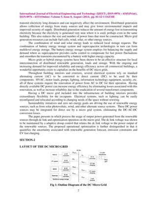
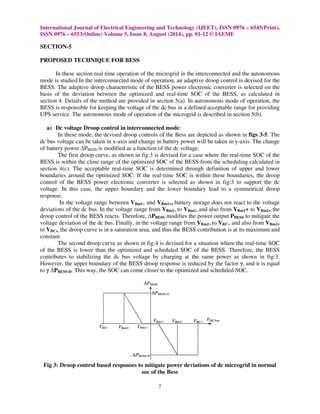
iv. DC BUS VOLTAGE PROFILE
Fig 11: Dc bus voltage with time(s) on x-axis and bus voltage(v) on y-axis
CONCLUSION
The renewable power which can be produced from the renewable resources can be integrated
by the accumulated model. By this accumulated model the power for the individual time can be
calculated. At particular time, the load will be connected to the dc bus. The renewable power will be
served to the load through dc bus. If there is any uncertainty affiliated with the forecast of aggregated
wind and pv based power generation was created and used to quantify the energy reserve of the
battery energy storage system. The battery is parallel connected with the super capacitor to form
multi level energy storage. The battery plays critical role for compensating the power fluctuations.
The control proposed is here adaptive droop control in that the voltage-power droop curves are
modified depending on the outcome of operational optimization. These voltage-power droop curves
satisfy the load forecast uncertainties. The resulting energy system serves local stationary and ev
based mobile consumers, and it is a good citizen within the main gird as it reduces emission by local
usage of wind and solar energy.
REFERENCES
[1] F.Giraud and Z.M.Salameh, “Steady-State Performance of a Grid Connected Rooftop Hybrid
Wind-Photovoltaic Power System with Battery Storage”, IEEE Trans. Energy Convers.,
vol.16, no.1, pp.1-7, Mar.2001.
[2] B.S.Borowy and Z.M.Salameh, “Methodology for Optimally Sizing the Combination of
Battery Bank and PV Array in a Wind/PV Hybrid System”, IEEE Trans. Energy Convers.,
vol.11, no.2, pp.367-375, Mar.1996.
[3] A.L.Dimeas and N.D.Hatziargyriou, “Operation of a Multiagent System for Microgrid
Control”, IEEE Trans. Power Syst., vol.20, no.3, pp.1447-1455, Mar.2005.
[4] F.Katiraei and M.R.Iravani, “Power Management Strategies for a Micro Grid with Multiple
Distributed Generation Units”, IEEETrans. PowerSyst”, vol.21, no.4, pp. 1821-1831,
Nov. 2006.
[5] A.G.Madureira and J.A.PecasLopes, “Coordinated Voltage Support in Distribution Networks
with Distribution Generation and Microgrids”, IET Renew. Power Generat., vol.3, no.4,
pp.439-454,Dev.2009.](https://image.slidesharecdn.com/integrationofrenewableresourcesfordcmicrogridapplications-141110060702-conversion-gate01/85/Integration-of-renewable-resources-for-dc-micro-grid-applications-11-320.jpg)
![International Journal of Electrical Engineering and Technology (IJEET), ISSN 0976 – 6545(Print),
ISSN 0976 – 6553(Online) Volume 5, Issue 8, August (2014), pp. 01-12 © IAEME
12
[6] R.Majumder, B.Chaudhuri, A.Ghosh, R.Majumder, G.Ledwich and F.Zare, “Improvement of
Stability and Load Sharing in an Autonomous Microgrid using Supplementary
Droopcontrolloop”, IEEE Trans .PowerSyst., vol.25, no.2, pp.768-808, May 2010.
[7] D.Westermann, S.Nicolai and P.Bretschneider, “Energy Management for Distribution
Networks with Storage Systems-A Hierarchical Approach”, in proc.IEEE PES General
Meeting, Convers.Del.Electr. Energy 21st Century, Pittsburgh, PA, USA, Jul.2008.
[8] A.Chaouachi, R.M.Kamel, R.Andoulsi and K.Nagasaka, “Multi-Objective Intelligent Energy
Management for a Microgrid”, IEEE Trans.Ind.Electron., vol.60, no.4, pp.1688-1699,
Apr.2013.
[9] Martin Kaltsvhmitt, Wolfgang Strechier and Reas Wiese, “Renewable Energy Technology,
Economics and Environment”, ISBN 978-3-540-70947-3 Springer Berlin Heidelberg New
York.
[10] Dr.S.M.Ali, Prof. K.K.Rout and Bijayini Mohanty, “Application of Renewable Energy
Sources for Effective Energy Management”, International Journal of Electrical Engineering
Technology (IJEET), Volume 1, Issue 1, 2010, pp. 18 - 31, ISSN Print : 0976-6545,
ISSN Online: 0976-6553.
AUTHOR’S DETAIL
G. MAHESH KUMAR has received the B.Tech degree in EEE from Siddartha
institute of science and technology, Puttur in the year of 2012. Present he is pursuing
M.Tech in power electronics in Kuppam Engineering College. Kuppam.
Y. DAMODHARAM has obtained his B.Tech in EEE from Kuppam Engineering
College affiliated to JNTUH in the year 2006. He completed M.Tech in power system
emphasis on High Voltage Engineering from JNTU Kakinada in the year 2010.
Currently working as Associate Professor in Kuppam Engineering College in the
Department of EEE. His area of research is renewable energy sources, high Voltage
engineering, power systems technology.
VELAPPAGARI SEKHAR has obtained his B.Tech in Siddhartha institute of
engineering and technology, Puttur in the year 2008. He completed M.E in power
system engineering from Velammal Engineering College, Chennai in the year 2010.
Since 2012 he is a member in LMISTE, LMSESI and in 2014 he got membership in
AMIE. He currently working as Assistant professor in Kuppam Engineering College
with towards working as Ph.D at VIT. Vellore. His research includes the areas of interest in power
system stability analysis protection.
S. SURESH has obtained his B.Tech and M.Tech in Kuppam Engineering College in
the year 2010, 2014. Currently working as Assistant professor in C.R. Engineering
College in the department of EEE. His research includes the areas of interest in power
electronics.](https://image.slidesharecdn.com/integrationofrenewableresourcesfordcmicrogridapplications-141110060702-conversion-gate01/85/Integration-of-renewable-resources-for-dc-micro-grid-applications-12-320.jpg)

This document summarizes a research paper that proposes integrating renewable energy resources like wind and solar power for DC microgrid applications. The document first provides background on microgrids and discusses how DC microgrids can integrate renewable sources more efficiently by eliminating conversion losses. It then outlines the layout of the proposed DC microgrid, which includes renewable generators, battery energy storage, supercapacitors, electric vehicle charging, and grid integration. The document goes on to provide an overview of the optimized scheduling approach used to balance supply and demand on the microgrid. This approach aggregates renewable forecast data, assigns battery reserves, and formulates an emission-constrained cost optimization to schedule microgrid resources day-ahead. Mathematical equations are provided to describe the